SST39SF040 4 Mbit MPF: Features, Datasheet and Timing Diagram
5V V SST39 MPF™ 32 Pin Memory IC SST39 MPF™ Series SST39SF040 4 Mb kb 14.05mm mm 25mA mA 8b b
Unit Price: $2.509845
Ext Price: $2.51


5V V SST39 MPF™ 32 Pin Memory IC SST39 MPF™ Series SST39SF040 4 Mb kb 14.05mm mm 25mA mA 8b b
The SST39SF040 is CMOS Multi-Purpose Flash (MPF) device manufactured with SST proprietary, high performance CMOS SuperFlash technology. The SST39SF040 writes (Program or Erase) with a 4.5-5.5V power supply, and conforms to JEDEC standard pinouts for x8 memories. Furthermore, Huge range of Semiconductors, Capacitors, Resistors and IcS in stock. Welcome RFQ.

What Is Flash Memory?
SST39SF040 Pinout
The following figure is the diagram of SST39SF040 pinout.

Pinout
SST39SF040 CAD Model
The followings are SST39SF040 Symbol, Footprint, and 3D Model.
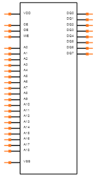
Symbol
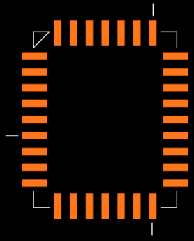
Footprint
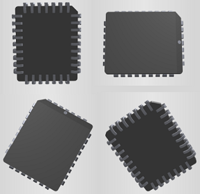
3D Model
SST39SF040 Overview
The SST39SF040 is CMOS Multi-Purpose Flash (MPF) manufactured with SST's proprietary, high performance CMOS SuperFlash technology. The split-gate cell design and thick oxide tunneling injector attain better reliability and manufacturability compared with alternate approaches. The SST39SF040 device writes (Program or Erase) with a 4.5-5.5V power supply. The SST39SF040 device conforms to JEDEC standard pinouts for x8 memories. Featuring high performance Byte-Program, the SST39SF040 device provides a maximum Byte-Program time of 20 µsec. To meet high density, surface mount requirements, the SST39SF040 is offered in 32-lead PLCC package.
This article provides you with a basic overview of the SST39SF040 4 Mbit MPF, including its pin descriptions, features and specifications, etc., to help you quickly understand what SST39SF040 is.
SST39SF040 Features
● Organized as 512K x8
● Single 4.5-5.5V Read and Write Operations
● Superior Reliability
◆ Endurance: 100,000 Cycles (typical)
◆ Greater than 100 years Data Retention
● Low Power Consumption (typical values at 14 MHz)
◆ Active Current: 10 mA (typical)
◆ Standby Current: 30 µA (typical)
● Sector-Erase Capability
◆ Uniform 4 KByte sectors
● Fast Read Access Time:
◆ 55 ns
◆ 70 ns
● Latched Address and Data
● Automatic Write Timing
◆ Internal VPP Generation
● Fast Erase and Byte-Program
◆ Sector-Erase Time: 18 ms (typical)
◆ Chip-Erase Time: 70 ms (typical)
◆ Byte-Program Time: 14 µs (typical)
◆ Chip Rewrite Time: 8 seconds (typical) for SST39SF040
● End-of-Write Detection
◆ Toggle Bit
◆ Data# Polling
● TTL I/O Compatibility
● JEDEC Standard
◆ Flash EEPROM Pinouts and command sets
● Packages Available: 32-lead PLCC
● RoHS compliant
SST39SF040 Advantage
The SST39SF040 device is suited for applications that require convenient and economical updating of program, configuration, or data memory. For all system applications, it significantly improves performance and reliability, while lowering power consumption. It inherently uses less energy during erase and program than alternative flash technologies. The total energy consumed is a function of the applied voltage, current, and time of application. Since for any given voltage range, the SuperFlash technology uses less current to program and has a shorter erase time, the total energy consumed during any Erase or Program operation is less than alternative flash technologies. The device also improves flexibility while lowering the cost for program, data, and configuration storage applications.
The device uses Toggle Bit or Data# Polling to indicate the completion of Program operation. To protect against inadvertent write, it has on-chip hardware and Software Data Protection schemes. Designed, manufactured, and tested for a wide spectrum of applications, the device is offered with a guaranteed typical endurance of 100,000 cycles. Data retention is rated at greater than 100 years. The SuperFlash technology provides fixed Erase and Program times, independent of the number of Erase/Program cycles that have occurred. Therefore the system software or hardware does not have to be modified or de-rated as is necessary with alternative flash technologies, whose Erase and Program times increase with accumulated Erase/Program cycles.
Specifications
- TypeParameter
- Factory Lead Time1 Weeks
- Mounting Type
The "Mounting Type" in electronic components refers to the method used to attach or connect a component to a circuit board or other substrate, such as through-hole, surface-mount, or panel mount.
Surface Mount - Package / Case
refers to the protective housing that encases an electronic component, providing mechanical support, electrical connections, and thermal management.
32-LCC (J-Lead) - Surface Mount
having leads that are designed to be soldered on the side of a circuit board that the body of the component is mounted on.
YES - Number of Pins32
- Memory TypesNon-Volatile
- Operating Temperature
The operating temperature is the range of ambient temperature within which a power supply, or any other electrical equipment, operate in. This ranges from a minimum operating temperature, to a peak or maximum operating temperature, outside which, the power supply may fail.
-40°C~85°C TA - Packaging
Semiconductor package is a carrier / shell used to contain and cover one or more semiconductor components or integrated circuits. The material of the shell can be metal, plastic, glass or ceramic.
Tube - Series
In electronic components, the "Series" refers to a group of products that share similar characteristics, designs, or functionalities, often produced by the same manufacturer. These components within a series typically have common specifications but may vary in terms of voltage, power, or packaging to meet different application needs. The series name helps identify and differentiate between various product lines within a manufacturer's catalog.
SST39 MPF™ - Published2000
- JESD-609 Code
The "JESD-609 Code" in electronic components refers to a standardized marking code that indicates the lead-free solder composition and finish of electronic components for compliance with environmental regulations.
e3 - Pbfree Code
The "Pbfree Code" parameter in electronic components refers to the code or marking used to indicate that the component is lead-free. Lead (Pb) is a toxic substance that has been widely used in electronic components for many years, but due to environmental concerns, there has been a shift towards lead-free alternatives. The Pbfree Code helps manufacturers and users easily identify components that do not contain lead, ensuring compliance with regulations and promoting environmentally friendly practices. It is important to pay attention to the Pbfree Code when selecting electronic components to ensure they meet the necessary requirements for lead-free applications.
yes - Part Status
Parts can have many statuses as they progress through the configuration, analysis, review, and approval stages.
Active - Moisture Sensitivity Level (MSL)
Moisture Sensitivity Level (MSL) is a standardized rating that indicates the susceptibility of electronic components, particularly semiconductors, to moisture-induced damage during storage and the soldering process, defining the allowable exposure time to ambient conditions before they require special handling or baking to prevent failures
3 (168 Hours) - Number of Terminations32
- ECCN Code
An ECCN (Export Control Classification Number) is an alphanumeric code used by the U.S. Bureau of Industry and Security to identify and categorize electronic components and other dual-use items that may require an export license based on their technical characteristics and potential for military use.
3A991.B.1.A - Terminal Finish
Terminal Finish refers to the surface treatment applied to the terminals or leads of electronic components to enhance their performance and longevity. It can improve solderability, corrosion resistance, and overall reliability of the connection in electronic assemblies. Common finishes include nickel, gold, and tin, each possessing distinct properties suitable for various applications. The choice of terminal finish can significantly impact the durability and effectiveness of electronic devices.
Matte Tin (Sn) - Voltage - Supply
Voltage - Supply refers to the range of voltage levels that an electronic component or circuit is designed to operate with. It indicates the minimum and maximum supply voltage that can be applied for the device to function properly. Providing supply voltages outside this range can lead to malfunction, damage, or reduced performance. This parameter is critical for ensuring compatibility between different components in a circuit.
4.5V~5.5V - Terminal Position
In electronic components, the term "Terminal Position" refers to the physical location of the connection points on the component where external electrical connections can be made. These connection points, known as terminals, are typically used to attach wires, leads, or other components to the main body of the electronic component. The terminal position is important for ensuring proper connectivity and functionality of the component within a circuit. It is often specified in technical datasheets or component specifications to help designers and engineers understand how to properly integrate the component into their circuit designs.
QUAD - Peak Reflow Temperature (Cel)
Peak Reflow Temperature (Cel) is a parameter that specifies the maximum temperature at which an electronic component can be exposed during the reflow soldering process. Reflow soldering is a common method used to attach electronic components to a circuit board. The Peak Reflow Temperature is crucial because it ensures that the component is not damaged or degraded during the soldering process. Exceeding the specified Peak Reflow Temperature can lead to issues such as component failure, reduced performance, or even permanent damage to the component. It is important for manufacturers and assemblers to adhere to the recommended Peak Reflow Temperature to ensure the reliability and functionality of the electronic components.
245 - Number of Functions1
- Supply Voltage
Supply voltage refers to the electrical potential difference provided to an electronic component or circuit. It is crucial for the proper operation of devices, as it powers their functions and determines performance characteristics. The supply voltage must be within specified limits to ensure reliability and prevent damage to components. Different electronic devices have specific supply voltage requirements, which can vary widely depending on their design and intended application.
5V - Terminal Pitch
The center distance from one pole to the next.
1.27mm - Time@Peak Reflow Temperature-Max (s)
Time@Peak Reflow Temperature-Max (s) refers to the maximum duration that an electronic component can be exposed to the peak reflow temperature during the soldering process, which is crucial for ensuring reliable solder joint formation without damaging the component.
40 - Base Part Number
The "Base Part Number" (BPN) in electronic components serves a similar purpose to the "Base Product Number." It refers to the primary identifier for a component that captures the essential characteristics shared by a group of similar components. The BPN provides a fundamental way to reference a family or series of components without specifying all the variations and specific details.
SST39SF040 - Pin Count
a count of all of the component leads (or pins)
32 - Operating Supply Voltage
The voltage level by which an electrical system is designated and to which certain operating characteristics of the system are related.
5V - Power Supplies
an electronic circuit that converts the voltage of an alternating current (AC) into a direct current (DC) voltage.?
5V - Memory Size
The memory capacity is the amount of data a device can store at any given time in its memory.
4Mb 512K x 8 - Nominal Supply Current
Nominal current is the same as the rated current. It is the current drawn by the motor while delivering rated mechanical output at its shaft.
25mA - Access Time
Access time in electronic components refers to the amount of time it takes for a system to retrieve data from memory or storage once a request has been made. It is typically measured in nanoseconds or microseconds and indicates the speed at which data can be accessed. Lower access time values signify faster performance, allowing for more efficient processing in computing systems. Access time is a critical parameter in determining the overall responsiveness of electronic devices, particularly in applications requiring quick data retrieval.
70ns - Memory Format
Memory Format in electronic components refers to the specific organization and structure of data storage within a memory device. It defines how data is stored, accessed, and managed within the memory module. Different memory formats include RAM (Random Access Memory), ROM (Read-Only Memory), and various types of flash memory. The memory format determines the speed, capacity, and functionality of the memory device, and it is crucial for compatibility with other components in a system. Understanding the memory format is essential for selecting the right memory module for a particular application or device.
FLASH - Memory Interface
An external memory interface is a bus protocol for communication from an integrated circuit, such as a microprocessor, to an external memory device located on a circuit board.
Parallel - Data Bus Width
The data bus width in electronic components refers to the number of bits that can be transferred simultaneously between the processor and memory. It determines the amount of data that can be processed and transferred in a single operation. A wider data bus allows for faster data transfer speeds and improved overall performance of the electronic device. Common data bus widths include 8-bit, 16-bit, 32-bit, and 64-bit, with higher numbers indicating a larger capacity for data transfer. The data bus width is an important specification to consider when evaluating the speed and efficiency of a computer system or other electronic device.
8b - Organization
In the context of electronic components, the parameter "Organization" typically refers to the arrangement or structure of the internal components within a device or system. It can describe how various elements such as transistors, resistors, capacitors, and other components are physically arranged and interconnected on a circuit board or within a semiconductor chip.The organization of electronic components plays a crucial role in determining the functionality, performance, and efficiency of a device. It can impact factors such as signal propagation, power consumption, thermal management, and overall system complexity. Engineers carefully design the organization of components to optimize the operation of electronic devices and ensure reliable performance.Different types of electronic components may have specific organizational requirements based on the intended application and design considerations. For example, integrated circuits may have a highly compact and intricate organization to maximize functionality within a small footprint, while larger electronic systems may have a more modular and distributed organization to facilitate maintenance and scalability.
512KX8 - Write Cycle Time - Word, Page
Write Cycle Time - Word, Page refers to the duration required to write data to a specific memory cell or a page of memory in electronic components, particularly in non-volatile memories like Flash or EEPROM. It indicates the time taken to complete a writing operation for a single word or an entire page of data. This parameter is crucial for determining the performance and speed of memory devices in applications where quick data storage is essential. It impacts the overall efficiency in data handling, affecting both read and write speeds in memory-related operations.
20μs - Address Bus Width
A computer system has an address bus with 8 parallel lines. This means that the address bus width is 8 bits.
19b - Density
In electronic components, "Density" refers to the mass or weight of a material per unit volume. It is a physical property that indicates how tightly packed the atoms or molecules are within the material. The density of a component can affect its performance and characteristics, such as its strength, thermal conductivity, and electrical properties. Understanding the density of electronic components is important for designing and manufacturing processes to ensure optimal performance and reliability.
4 Mb - Standby Current-Max
Standby Current-Max refers to the maximum amount of current that an electronic component or device consumes while in a low-power standby mode. This parameter is critical for power management, especially in battery-operated devices, as it indicates how efficiently the device can conserve energy when not actively in use. A lower Standby Current-Max value is typically desirable, as it contributes to longer battery life and reduced energy consumption. Manufacturers specify this value to help engineers select components that meet specific power efficiency requirements in their designs.
0.0001A - Sync/Async
In the context of electronic components, the parameter "Sync/Async" refers to the synchronization mode of operation. Synchronous operation means that the component operates in coordination with an external clock signal. This ensures that data is transmitted or processed at specific intervals determined by the clock signal, allowing for precise timing and coordination between different components in a system.Asynchronous operation, on the other hand, means that the component does not rely on an external clock signal for its operation. Instead, it processes data at its own pace, which can lead to more flexibility but may also result in timing issues if not properly managed.The choice between synchronous and asynchronous operation depends on the specific requirements of the system and the desired level of coordination and timing precision.
Asynchronous - Word Size
Word "size" refers to the amount of data a CPU's internal data registers can hold and process at one time.
8b - Programming Voltage
A special high-voltage supply that supplies the potential and energy for altering the state of certain nonvolatile memory arrays. On some devices, the presence of VPP also acts as a program enable signal (P).
5V - Data Polling
Data Polling is a process used in electronic components to retrieve data at regular intervals from a sensor or device. It involves checking or querying the device for updated information, ensuring that the most current data is accessible for processing or analysis. This technique is commonly used in systems where continuous monitoring is necessary, allowing for timely responses based on the latest data collected. Data Polling can impact system performance, as it may introduce delays or consume resources depending on the polling frequency and the efficiency of the implemented protocol.
YES - Toggle Bit
The toggle bit is a control mechanism in electronic components that allows a circuit to switch between two states, typically representing binary values of 0 and 1. It is commonly used in digital systems to change the status of a device or memory cell each time it is activated. The toggle bit maintains its state until it receives a new signal that alters its value, making it essential for operations such as counters and flip-flops. This functionality enables efficient data storage, retrieval, and manipulation in various electronic applications.
YES - Command User Interface
The term "Command User Interface" in electronic components refers to the method by which a user interacts with a device or system through issuing commands. This interface allows users to input instructions or requests to control the operation of the electronic component. The Command User Interface can take various forms, such as physical buttons, touchscreens, voice commands, or software-based interfaces. It plays a crucial role in enabling users to interact with and utilize the functionalities of electronic components effectively. The design and implementation of a Command User Interface are essential considerations in ensuring user-friendly and intuitive operation of electronic devices.
YES - Number of Sectors/Size128
- Sector Size
Sector size in electronic components refers to the minimum unit of data that can be read or written to the storage device, such as a hard drive or solid-state drive. It represents the smallest amount of data that can be accessed at a time within a storage device. The sector size is typically measured in bytes, with common sizes being 512 bytes or 4 kilobytes.Having a larger sector size can improve the efficiency of data storage and retrieval processes, as it reduces the overhead associated with accessing and managing smaller units of data. However, the choice of sector size can also impact the overall performance and compatibility of the storage device with different systems and applications. It is important to consider the sector size when configuring storage devices and optimizing data access speeds.
4K - Height2.84mm
- Length14.05mm
- Width11.51mm
- REACH SVHC
The parameter "REACH SVHC" in electronic components refers to the compliance with the Registration, Evaluation, Authorization, and Restriction of Chemicals (REACH) regulation regarding Substances of Very High Concern (SVHC). SVHCs are substances that may have serious effects on human health or the environment, and their use is regulated under REACH to ensure their safe handling and minimize their impact.Manufacturers of electronic components need to declare if their products contain any SVHCs above a certain threshold concentration and provide information on the safe use of these substances. This information allows customers to make informed decisions about the potential risks associated with using the components and take appropriate measures to mitigate any hazards.Ensuring compliance with REACH SVHC requirements is essential for electronics manufacturers to meet regulatory standards, protect human health and the environment, and maintain transparency in their supply chain. It also demonstrates a commitment to sustainability and responsible manufacturing practices in the electronics industry.
No SVHC - Radiation Hardening
Radiation hardening is the process of making electronic components and circuits resistant to damage or malfunction caused by high levels of ionizing radiation, especially for environments in outer space (especially beyond the low Earth orbit), around nuclear reactors and particle accelerators, or during nuclear accidents or nuclear warfare.
No - RoHS Status
RoHS means “Restriction of Certain Hazardous Substances” in the “Hazardous Substances Directive” in electrical and electronic equipment.
ROHS3 Compliant - Lead Free
Lead Free is a term used to describe electronic components that do not contain lead as part of their composition. Lead is a toxic material that can have harmful effects on human health and the environment, so the electronics industry has been moving towards lead-free components to reduce these risks. Lead-free components are typically made using alternative materials such as silver, copper, and tin. Manufacturers must comply with regulations such as the Restriction of Hazardous Substances (RoHS) directive to ensure that their products are lead-free and environmentally friendly.
Lead Free
SST39SF040 Functional Block Diagram
The following is the Functional Block Diagram of SST39SF040.
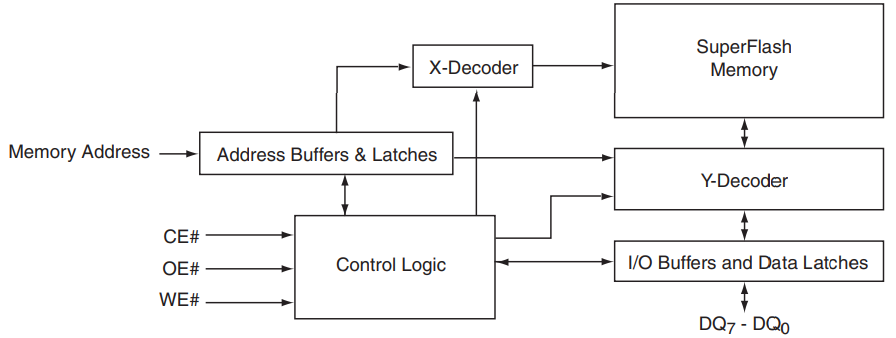
Functional Block Diagram
SST39SF040 Timing Diagram
The following diagram shows the SST39SF040 Timing Diagram.
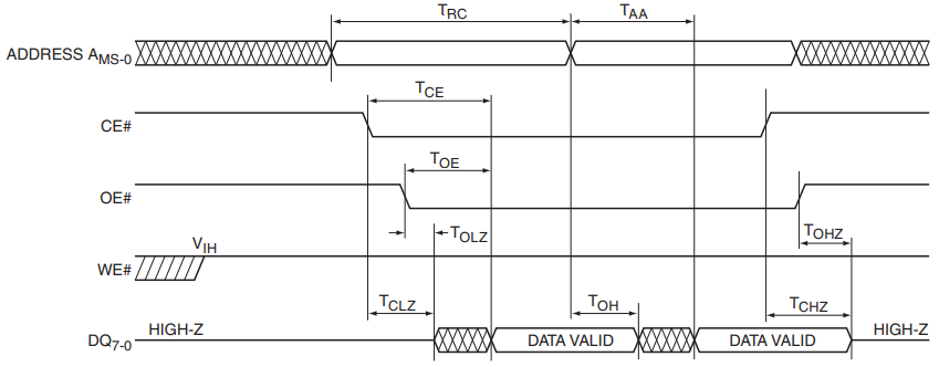
Read Cycle Timing Diagram
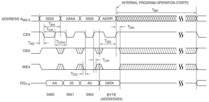
CE# Controlled Program Cycle Timing Diagram
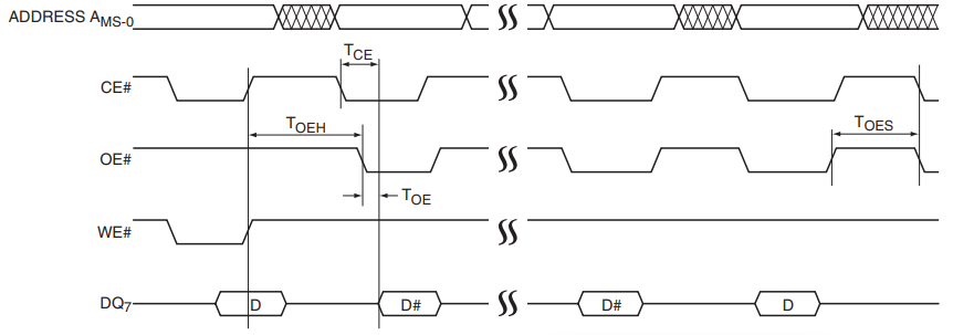
Data# Polling Timing Diagram
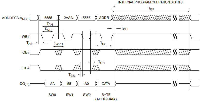
WE# Controlled Program Cycle Timing Diagram
Parts with Similar Specs
- ImagePart NumberManufacturerPackage / CaseNumber of PinsMemory TypeDensityAddress Bus WidthAccess TimeSupply VoltageRadiation HardeningView Compare
SST39SF040-70-4I-NHE
32-LCC (J-Lead)
32
Non-Volatile
4 Mb
19 b
70ns
5 V
No
32-LCC (J-Lead)
32
Non-Volatile
4 Mb
19 b
70ns
3 V
No
32-LCC (J-Lead)
32
Non-Volatile
4 Mb
19 b
70ns
3 V
No
32-LCC (J-Lead)
32
Non-Volatile
4 Mb
19 b
70ns
3 V
No
32-LCC (J-Lead)
32
Non-Volatile
4 Mb
19 b
-
3 V
No
SST39SF040 Package
The following diagram shows the SST39SF040 package.
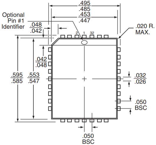
Top View
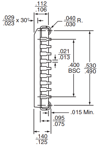
Side View
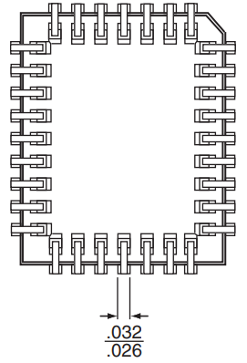
Bottom View
SST39SF040 Manufacturer
Microchip Technology Inc. is a leading provider of microcontroller and analog semiconductors, providing low-risk product development, lower total system cost and faster time to market for thousands of diverse customer applications worldwide. Headquartered in Chandler, Arizona, Microchip offers outstanding technical support along with dependable delivery and quality.
Trend Analysis
Datasheet PDF
- Datasheets :
- PCN Packaging :
- PCN Design/Specification :
- ConflictMineralStatement :
How is SST39SF040 programmed?
The SST39SF040 is programmed on a byte-by-byte basis.
What are the advantages of the Chip-Erase operation provided by SST39SF040?
The SST39SF040 provides Chip-Erase operation, which allows the user to erase the entire memory array to the “1s” state. This is useful when the entire device must be quickly erased.
In order to optimize the system's Write cycle time, how many software means does SST39SF040 provide to detect the completion of Write (Program or Erase) cycles?
The SST39SF040 provides two software means to detect the completion of a Write (Program or Erase) cycle, in order to optimize the system Write cycle time.
What features does SST39SF040 provide to protect non-volatile data from accidental writes?
The SST39SF040 provides both hardware and software features to protect nonvolatile data from inadvertent writes.
What about SST39SF040's Program and Erasure?
The SST39SF040 provides the JEDEC approved Software Data Protection scheme for all data alteration operations, i.e., Program and Erase.
 OPA2134 Audio Operational Amplifiers: Pinout, Datasheet and Replacement
17 September 202114454
 LIS3DH vs. ADXL345 Which one is better?
23 April 20225366
 SP2526A USB Power Distribution Switch: Pinout, Equivalent and Datasheet
15 March 2022418
 L6203 Bridge Driver: Circuit, Pinout, and Datasheet
22 October 20214672
 UC3843 PWM Controller: Pinout, Datasheet and Uses
16 August 202142667
 SST25VF040B 4-Mbit SPI Serial Flash: Pinout, Equivalent and Datasheet
31 March 2022913
 PIC16F876 Microcontroller: Features, Pinout, and Datasheet
23 November 20216844
![AD584 Precision Voltage Reference: Pinout, Features and Datasheet [FAQ]](https://res.utmel.com/Images/Article/0f6e8ef3-90eb-47b0-bdf7-30e675aaf8f5.png) AD584 Precision Voltage Reference: Pinout, Features and Datasheet [FAQ]
AD584 Precision Voltage Reference: Pinout, Features and Datasheet [FAQ]06 May 20222055
 SR44 vs LR44 Which Battery Should You Use
21 August 2025752
 What is Uninterruptible Power Supply (UPS)?
08 April 20214629
 RTD Sensors: Working Principle, Features and Applications
22 May 202512102
 Manifold Absolute Pressure (MAP) Sensor: Working Principles, Structure, and Types
31 March 202543650
 What are Weight Sensors?
31 October 202516347
 UMD Receives $2M NSF Grant for Advancement of Semiconductor Technology and Workforce Training
27 September 20231959
 What is CPLD (Complex Programmable Logic Device)?
15 October 202510560
 Modeling, Modulation Analysis of Filter-Integrated Three-Switch Boost Inverter
12 April 20232872
Microchip Technology
In Stock: 1310
Minimum: 1 Multiples: 1
Qty
Unit Price
Ext Price
1
$2.509845
$2.51
10
$2.367778
$23.68
100
$2.233753
$223.38
500
$2.107314
$1,053.66
1000
$1.988032
$1,988.03
Not the price you want? Send RFQ Now and we'll contact you ASAP.
Inquire for More Quantity


