
 Product
 Brand
Brand Articles
 Tools
Tools
Getting Started with STM32F756ZG Microcontroller Programming


Microcontroller 3V
Learn how to set up, program, and debug the STM32F756ZG microcontroller. Explore STM32CubeIDE, flash programming, and troubleshooting techniques.
Product Introduction
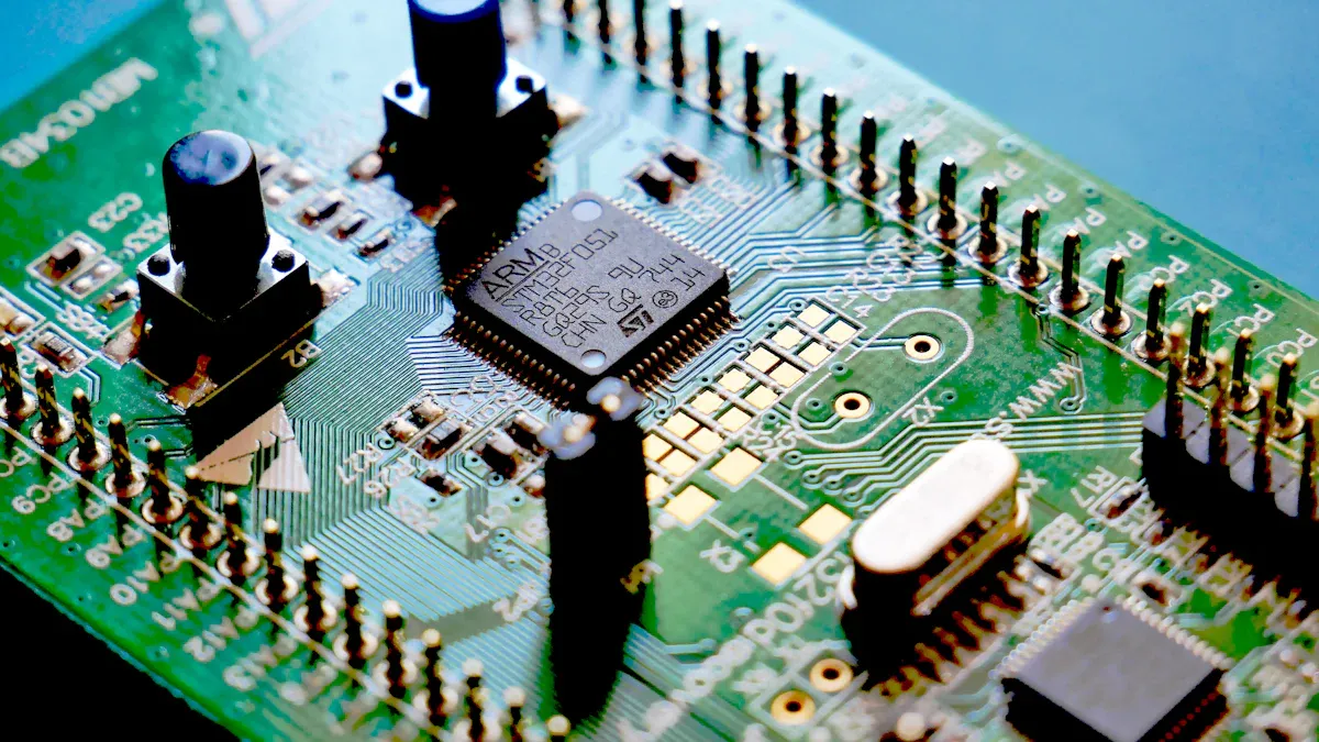
The STM32F756ZG is a powerful microcontroller designed for demanding embedded systems. You can achieve exceptional performance with its 216 MHz core speed, delivering up to 462 DMIPS. This makes it faster than many microcontrollers in its class. It includes advanced features like a Chrom-ART Accelerator™ and an LCD-TFT controller, allowing you to create rich graphical interfaces. Connectivity options such as USB and Ethernet simplify integration into modern devices. Its low-power modes help conserve energy, making it ideal for portable applications. By mastering its basics, you unlock its full potential for programming innovative solutions.
Setting Up the STM32F756ZG Development Environment
Before you can start programming the STM32F756ZG microcontroller, you need to set up the development environment. This involves installing the necessary software, configuring the hardware, and ensuring proper communication between your computer and the board. Follow these steps to get started.
Installing STM32CubeIDE
STM32CubeIDE is an integrated development environment (IDE) designed specifically for STM32 microcontrollers. It combines code editing, debugging, and project management tools in one platform. To install it:
- Visit the official STMicroelectronics website and navigate to the STM32CubeIDE download page.
- Select the version compatible with your operating system (Windows, macOS, or Linux).
- Download the installer and run it. Follow the on-screen instructions to complete the installation.
- Once installed, launch STM32CubeIDE and create a workspace directory where your projects will be stored.
Tip: Keep your workspace organized by creating separate folders for different projects. This will make it easier to manage your files and data.
Configuring the STM32F756ZG Board
After installing the IDE, you need to configure the STM32F756ZG board to prepare it for programming. Here’s how:
- Connect the board to your computer using a USB cable. Ensure the cable supports both power and data transfer.
- Check the board’s jumpers and switches. These control the power source and boot mode. Refer to the user manual for the correct settings.
- Power on the board. You should see the onboard LED light up, indicating that the board is receiving power.
- Open STM32CubeIDE and create a new project. Select the STM32F756ZG microcontroller from the device list. This will load the default configuration for the board.
Note: If you’re unsure about the jumper settings, consult the STM32F756ZG datasheet. It provides detailed information about the board’s hardware configuration.
Installing Drivers for Debugging and Flash Programming
To communicate with the STM32F756ZG board, you need to install the appropriate drivers. These drivers enable debugging and flash programming, which are essential for testing and deploying your code. Follow these steps:
- Download the ST-Link USB driver from the STMicroelectronics website.
- Install the driver on your computer. Restart your system if prompted.
- Verify the installation by connecting the board to your computer. Open the Device Manager (on Windows) or System Information (on macOS) and check if the ST-Link device appears under the USB devices list.
- Install the STM32CubeProgrammer software. This tool allows you to flash data to the microcontroller’s memory and perform advanced debugging functions.
Important: Always use the latest version of the drivers and software to ensure compatibility with your operating system and the STM32F756ZG board.
Once you’ve completed these steps, your development environment is ready. You can now write, debug, and flash programs to the STM32F756ZG microcontroller.
Verifying the Setup with a Test Program
Once you have installed the necessary software and configured your STM32F756ZG board, it’s time to verify that everything is working correctly. Running a simple test program ensures that your development environment is set up properly and that the board communicates with your computer.
Step 1: Create a New Project in STM32CubeIDE
- Open STM32CubeIDE and select your workspace directory.
- Click on File > New > STM32 Project.
- In the Target Selection window, search for
STM32F756ZGand select it from the list. - Choose the default settings for the project and click Finish. STM32CubeIDE will generate a basic project structure for you.
Tip: Name your project something simple like "TestProgram" to keep things organized.
Step 2: Write the Test Code
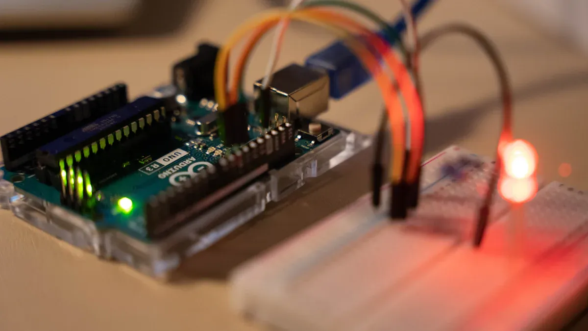
To verify the setup, you can write a simple program to blink an onboard LED. This is a common first step in microcontroller programming. Replace the contents of the main.c file with the following code:
#include "main.h"

void SystemClock_Config(void);
static void MX_GPIO_Init(void);

int main(void) {
    HAL_Init();
    SystemClock_Config();
    MX_GPIO_Init();

    while (1) {
        HAL_GPIO_TogglePin(GPIOB, GPIO_PIN_0); // Toggle LED
        HAL_Delay(500); // Delay for 500ms
    }
}

void SystemClock_Config(void) {
    // System clock configuration code (auto-generated by STM32CubeIDE)
}

static void MX_GPIO_Init(void) {
    GPIO_InitTypeDef GPIO_InitStruct = {0};

    __HAL_RCC_GPIOB_CLK_ENABLE(); // Enable GPIOB clock

    GPIO_InitStruct.Pin = GPIO_PIN_0; // Configure pin 0
    GPIO_InitStruct.Mode = GPIO_MODE_OUTPUT_PP;
    GPIO_InitStruct.Pull = GPIO_NOPULL;
    GPIO_InitStruct.Speed = GPIO_SPEED_FREQ_LOW;
    HAL_GPIO_Init(GPIOB, &GPIO_InitStruct);
}
This program toggles an LED connected to pin B0 every 500 milliseconds. It uses the HAL (Hardware Abstraction Layer) library, which simplifies peripheral configuration.
Step 3: Build and Flash the Program
- Click on the Build button (hammer icon) in STM32CubeIDE. This compiles your code and checks for errors.
- Connect your STM32F756ZG board to your computer using a USB cable.
- Click on the Debug button (bug icon) to flash the program onto the microcontroller.
Note: If you encounter errors during the build process, double-check your code and ensure the correct microcontroller is selected in the project settings.
Step 4: Observe the Results
After flashing the program, the onboard LED should start blinking. If it does, your setup is working correctly. If not, verify the following:
- The USB cable is properly connected.
- The correct drivers are installed.
- The jumper settings on the board are configured for programming mode.
Troubleshooting Tip: Use the STM32CubeProgrammer tool to check if the microcontroller is detected by your computer. This can help identify connection issues.
By completing this test, you confirm that your STM32F756ZG development environment is ready for more complex programming tasks.
Writing and Uploading Your First Program
Creating a New Project in STM32CubeIDE
To start programming the STM32F756ZG microcontroller, you need to create a new project in STM32CubeIDE. Follow these steps to set up your first program:
- Open STM32CubeIDE and select your workspace directory.
- Click on File > New > STM32 Project.
- In the Target Selection window, search for
STM32F756ZGand select it from the list. - Choose the default settings for the project and click Finish. STM32CubeIDE will generate a basic project structure for you.
Tip: Use a descriptive name for your project, such as "LED_Blink," to make it easier to identify later.
Once the project is created, STM32CubeIDE will automatically generate initialization code for the microcontroller. This code includes system clock configuration and peripheral setup, which are essential for running your program.
Writing Code to Blink an LED
Blinking an LED is a simple yet effective way to test your STM32F756ZG board. It helps you understand how to control GPIO pins and use basic functions. Replace the contents of the main.c file with the following code:
#include "main.h"

void SystemClock_Config(void);
static void MX_GPIO_Init(void);

int main(void) {
    HAL_Init();
    SystemClock_Config();
    MX_GPIO_Init();

    while (1) {
        HAL_GPIO_TogglePin(GPIOB, GPIO_PIN_0); // Toggle LED
        HAL_Delay(500); // Delay for 500ms
    }
}

void SystemClock_Config(void) {
    // System clock configuration code (auto-generated by STM32CubeIDE)
}

static void MX_GPIO_Init(void) {
    GPIO_InitTypeDef GPIO_InitStruct = {0};

    __HAL_RCC_GPIOB_CLK_ENABLE(); // Enable GPIOB clock

    GPIO_InitStruct.Pin = GPIO_PIN_0; // Configure pin 0
    GPIO_InitStruct.Mode = GPIO_MODE_OUTPUT_PP;
    GPIO_InitStruct.Pull = GPIO_NOPULL;
    GPIO_InitStruct.Speed = GPIO_SPEED_FREQ_LOW;
    HAL_GPIO_Init(GPIOB, &GPIO_InitStruct);
}
This code uses the HAL library to initialize the GPIO pin connected to the onboard LED. The HAL_GPIO_TogglePin function toggles the LED state, while the HAL_Delay function introduces a delay between toggles.
Note: If your board does not have an onboard LED, connect an external LED to pin B0 and use a resistor to limit the current.
Compiling and Debugging the Program
After writing the code, you need to compile and debug the program to ensure it works as intended.
- Click on the Build button (hammer icon) in STM32CubeIDE. This compiles your code and checks for errors.
- Connect your STM32F756ZG board to your computer using a USB cable.
- Click on the Debug button (bug icon) to flash the program onto the microcontroller.
Important: Ensure the ST-Link drivers are installed and the board is configured for programming mode.
Once the program is flashed, observe the LED on your STM32F756ZG board. It should blink every 500 milliseconds. If the LED does not blink, check the following:
- Verify the USB connection and jumper settings.
- Ensure the correct microcontroller is selected in the project settings.
- Use the STM32CubeProgrammer tool to confirm that the microcontroller is detected by your computer.
Debugging tools in STM32CubeIDE allow you to step through your code and monitor variables. Use these tools to identify issues and refine your program.
By completing these steps, you successfully write, compile, and debug your first program for the STM32F756ZG microcontroller. This foundational exercise prepares you for more advanced programming tasks.
Uploading the Program to the STM32F756ZG
Once you have written and compiled your code, the next step is to upload the program to the STM32F756ZG microcontroller. This process transfers your compiled code into the microcontroller's flash memory, allowing it to execute the instructions. Follow these steps to successfully upload your program.
Step 1: Connect the Board to Your Computer
Use a USB cable to connect the STM32F756ZG board to your computer. Ensure the cable supports both power and data transfer. Verify that the board powers on by checking the onboard LED. If the LED does not light up, confirm that the cable is securely connected and the board's jumper settings are correct.
Step 2: Select the Debug Configuration
In STM32CubeIDE, click on the Run > Debug Configurations menu. This opens a window where you can configure how the program will be uploaded and debugged. Select the configuration associated with your project. Ensure that the debugger is set to ST-Link, as this is the most common interface for STM32 microcontrollers.
Tip: If you are unsure about the debugger settings, use the default configuration provided by STM32CubeIDE. It is optimized for most STM32 boards, including the STM32F756ZG.
Step 3: Flash the Program
Click on the Debug button (represented by a bug icon) in STM32CubeIDE. The IDE will compile the code again, establish a connection with the microcontroller, and upload the program to its flash memory. During this process, you may see a progress bar indicating the upload status.
The successful writing and reading of data from flash memory confirm the reliability of the programming process. This ensures that the data remains intact after the operations, providing confidence in the microcontroller's ability to execute your program without errors.
Step 4: Verify the Program Execution
After the upload completes, the STM32CubeIDE debugger will start running your program. Observe the behavior of the microcontroller. For example, if you uploaded an LED blinking program, the onboard LED should begin blinking as expected. If the program does not run, check the following:
- Ensure the correct microcontroller is selected in the project settings.
- Verify that the USB cable is functioning properly.
- Confirm that the board's jumper settings are configured for programming mode.
Troubleshooting Tip: Use the STM32CubeProgrammer tool to check if the microcontroller is detected by your computer. This tool can also help you erase the flash memory or reset the microcontroller if needed.
Step 5: Disconnect the Debugger (Optional)
Once you verify that the program is running correctly, you can stop the debugger in STM32CubeIDE by clicking the Stop button (red square icon). Disconnect the USB cable if you no longer need to debug or modify the program. The microcontroller will continue running the uploaded program as long as it remains powered.
By following these steps, you can confidently upload your program to the STM32F756ZG microcontroller. This process is essential for testing and deploying your embedded applications.
Debugging STM32F756ZG Programs
Debugging is a crucial step in programming the STM32F756ZG microcontroller. It helps you identify and fix errors in your code, ensuring your program runs as intended. With the right tools and techniques, you can streamline the debugging process and save valuable development time.
Using the STM32CubeIDE Debugger
STM32CubeIDE offers a built-in debugger that simplifies the debugging process. It allows you to monitor variables, set breakpoints, and step through your code line by line. To use the debugger:
- Open your project in STM32CubeIDE.
- Click the Debug button (bug icon) to start the debugging session.
- Use the Variables tab to observe real-time changes in your program's data.
- Set breakpoints by clicking on the left margin of the code editor. This pauses the program at specific lines, letting you inspect its behavior.
The STM32CubeIDE debugger provides a user-friendly interface for troubleshooting. Its "1-click" debugging feature eliminates the need for manual configuration, making it ideal for beginners.
Debugging with ST-Link and Serial Wire Debug (SWD)
ST-Link is a hardware debugging tool designed for STM32 microcontrollers. It works seamlessly with Serial Wire Debug (SWD), a protocol that enables efficient communication between your computer and the microcontroller. To debug with ST-Link and SWD:
- Connect the ST-Link debugger to your STM32F756ZG board using the SWD pins.
- Ensure the ST-Link drivers are installed on your computer.
- In STM32CubeIDE, select ST-Link as the debugger in the project settings.
This setup allows you to flash programs and debug them simultaneously. SWD's low pin count makes it ideal for compact designs, while ST-Link ensures reliable communication during debugging sessions.
Common Debugging Techniques and Tools
Effective debugging requires a combination of techniques and tools. Here are some recommended practices:
- Use Debugging Frameworks: STM32Cube provides a robust framework for STM32 microcontrollers. It simplifies debugging and enhances performance.
- Monitor Flash Memory: Check the microcontroller's flash memory for corrupted data. Use STM32CubeProgrammer to erase or reprogram the flash if needed.
- Analyze Error Messages: Pay attention to error messages during compilation or debugging. They often point to specific issues in your code.
- Leverage Debug Probes: Debug probes like ST-Link offer advanced features for monitoring and troubleshooting.
The table below summarizes key debugging tools and techniques:
| Category | Description |
|---|---|
| STM32Cube | A framework designed for STM32 MCUs, offering high performance and ease of development. |
| Debugging | Provides a '1-click' solution for debugging with zero configuration. |
| Tools & Debug Probes | Lists supported debugging tools and options for configuration in the project file. |
By combining these techniques and tools, you can efficiently debug your STM32F756ZG programs and resolve errors with confidence.
Troubleshooting Connection and Flash Issues
When working with the STM32F756ZG microcontroller, you might encounter connection or flash-related issues. These problems can prevent your program from uploading or running correctly. Here’s how you can identify and resolve them.
Check the USB Connection
A faulty USB connection is a common cause of flash errors. Ensure the USB cable supports both power and data transfer. Some cables only provide power, which can lead to communication failures. Plug the cable into a different USB port on your computer to rule out port-specific issues.
Tip: Use a high-quality USB cable to avoid intermittent disconnections.
Verify Jumper Settings
Incorrect jumper settings can block the microcontroller from entering programming mode. Check the STM32F756ZG user manual for the correct jumper configuration. Ensure the jumpers are set to enable flash programming and debugging.
Inspect the ST-Link Driver
If the ST-Link driver is missing or outdated, your computer may fail to detect the microcontroller. Open your device manager (on Windows) or system information (on macOS) to confirm the ST-Link device appears. If it doesn’t, reinstall the driver from the STMicroelectronics website.
Resolve Flash Memory Errors
Flash memory errors can occur if the microcontroller’s memory is corrupted or full. Use the STM32CubeProgrammer tool to erase the flash memory before uploading a new program. This ensures the microcontroller has enough space for your code.
Debugging Connection Issues
If the microcontroller still doesn’t respond, try these steps:
- Restart your computer and reconnect the board.
- Use a different USB cable or ST-Link debugger.
- Check for physical damage to the board or connectors.
Troubleshooting Tip: If you see an error message during programming, note the exact text. Search for the error online or consult the STM32CubeIDE documentation for guidance.
By following these steps, you can resolve most connection and flash issues. Regularly updating your tools and drivers will also help prevent future problems.
Advanced Features of STM32F756ZG
Introduction to Flash Programming
Flash programming is a critical feature of the STM32F756ZG microcontroller. It allows you to store data in non-volatile flash memory, ensuring the data remains intact even after a power loss. This capability is essential for applications that require persistent storage, such as configuration settings or logs.
The STM32 microcontroller organizes its flash memory into pages and sectors. Understanding this structure is vital for efficient flash programming. You can use specific functions like flash_write_data and flash_read_data to interact with the memory. These functions simplify the process of writing and reading data, making it accessible even for beginners.
Key features of flash programming include:
- Retention of data after power loss.
- Functions like
flash_write_dataandflash_read_datafor easy memory access. - A structured memory layout with pages and sectors for organized storage.
By mastering flash programming, you can unlock the full potential of the STM32F756ZG for data-driven applications.
How to Write Data to Flash Memory
Writing data to flash memory involves several steps. First, you must unlock the flash control register using the hal_flash_unlock function. This step ensures you have permission to modify the memory. Next, erase the target memory sector using the hal_flashex_erase function. This operation clears the existing data, preparing the memory for new information.
Once the memory is ready, use the hal_flash_program function to write data. For example, the flash_write_data function simplifies this process by handling the low-level operations for you. After writing, lock the flash control register to prevent accidental modifications.
Here’s a simplified workflow:
- Unlock the flash control register.
- Erase the target memory sector.
- Write data using
flash_write_data. - Lock the flash control register.
This process ensures reliable data storage in the STM32F756ZG’s flash memory. Always verify the written data using the flash_read_data function to confirm its accuracy.
Interfacing with Peripherals (UART, I2C, SPI)
The STM32F756ZG microcontroller supports multiple communication interfaces, including UART, I2C, and SPI. These peripherals enable efficient data exchange between the microcontroller and external devices.
| Interface Type | Maximum Speed |
|---|---|
| I2C | Up to 4 interfaces |
| UART | 27 Mbit/s |
| SPI | Up to 50 Mbit/s |
UART is ideal for serial communication, offering high-speed data transfer. I2C provides a simple two-wire interface, making it suitable for low-speed peripherals like sensors. SPI delivers the fastest communication, perfect for high-speed devices like displays or memory modules.
To use these interfaces, configure the corresponding pins in STM32CubeIDE. The HAL library simplifies this process, providing functions to initialize and manage each peripheral. By leveraging these interfaces, you can expand the capabilities of your STM32F756ZG projects.
Exploring DMA and Low-Power Modes
Direct Memory Access (DMA) is a powerful feature of the STM32F756ZG microcontroller. It allows peripherals to transfer data directly to and from memory without involving the CPU. This reduces processing overhead and improves system efficiency. You can use DMA for tasks like transferring data from sensors to memory or streaming audio data to a speaker.
How DMA Works
DMA operates by setting up a channel between a peripheral and memory. You configure the source and destination addresses, along with the amount of data to transfer. Once activated, the DMA controller handles the transfer independently. This frees the CPU to focus on other tasks, boosting overall performance.
To use DMA, follow these steps:
- Enable the DMA controller in STM32CubeIDE.
- Configure the DMA channel for your peripheral.
- Write code to initialize the DMA transfer.
Here’s an example of initializing DMA for a UART peripheral:
HAL_UART_Receive_DMA(&huart1, buffer, sizeof(buffer));
DMA is ideal for applications requiring high-speed data transfer, such as real-time video processing or large data logging.
Exploring Low-Power Modes
The STM32F756ZG microcontroller offers several low-power modes to conserve energy. These modes reduce power consumption by disabling unused peripherals and slowing down the system clock. You can use low-power modes for battery-operated devices or applications requiring energy efficiency.
The key low-power modes include:
- Sleep Mode: The CPU stops, but peripherals remain active.
- Stop Mode: Most peripherals are disabled, but memory retains its state.
- Standby Mode: The system enters deep sleep, with only essential memory preserved.
To enter a low-power mode, use the HAL library functions. For example:
HAL_PWR_EnterSTOPMode(PWR_LOWPOWERREGULATOR_ON, PWR_STOPENTRY_WFI);
Low-power modes extend battery life and reduce heat generation, making them essential for portable devices.
By combining DMA and low-power modes, you can optimize the STM32F756ZG microcontroller for high-performance and energy-efficient applications.
You’ve now explored the foundational steps for programming and debugging the stm32f756zg microcontroller. From setting up the development environment to writing and uploading your first program, each step builds your confidence. Always refer to the reference manual for detailed instructions on configuring peripherals or troubleshooting issues. The datasheet is another essential resource for understanding the hardware specifications and pin configurations.
Practice is key to mastering microcontroller programming. Experiment with different peripherals and features. Use the reference manual to dive deeper into advanced topics like flash programming or DMA. The datasheet will guide you when interfacing with external components.
Finally, don’t hesitate to explore additional resources. Online forums, tutorials, and the reference manual can provide valuable insights. With consistent effort, you’ll unlock the full potential of the stm32f756zg for your embedded projects.
FAQ
What makes the STM32F756ZG microcontroller unique?
The STM32F756ZG stands out with its 216 MHz speed, advanced graphics capabilities, and versatile connectivity options like USB and Ethernet. Its low-power modes make it ideal for portable applications.
How do you troubleshoot a failed program upload?
Check the USB cable and jumper settings. Verify the ST-Link driver installation. Use STM32CubeProgrammer to erase flash memory or reset the microcontroller.
Can you use external peripherals with the STM32F756ZG?
Yes, you can interface with peripherals like sensors, displays, and memory modules using UART, I2C, or SPI. Configure pins in STM32CubeIDE and use HAL functions for communication.
What is the best way to debug your program?
Use STM32CubeIDE’s debugger to monitor variables and set breakpoints. For advanced debugging, connect an ST-Link debugger and enable Serial Wire Debug (SWD).
How do you conserve power in STM32F756ZG applications?
Enable low-power modes like Sleep, Stop, or Standby. Use HAL functions to configure these modes and disable unused peripherals to reduce energy consumption.
Specifications
- TypeParameter
- Lifecycle Status
Lifecycle Status refers to the current stage of an electronic component in its product life cycle, indicating whether it is active, obsolete, or transitioning between these states. An active status means the component is in production and available for purchase. An obsolete status indicates that the component is no longer being manufactured or supported, and manufacturers typically provide a limited time frame for support. Understanding the lifecycle status is crucial for design engineers to ensure continuity and reliability in their projects.
ACTIVE (Last Updated: 7 months ago) - Surface Mount
having leads that are designed to be soldered on the side of a circuit board that the body of the component is mounted on.
YES - Number of I/Os114
- Number of Terminations144
- ECCN Code
An ECCN (Export Control Classification Number) is an alphanumeric code used by the U.S. Bureau of Industry and Security to identify and categorize electronic components and other dual-use items that may require an export license based on their technical characteristics and potential for military use.
5A992.C - HTS Code
HTS (Harmonized Tariff Schedule) codes are product classification codes between 8-1 digits. The first six digits are an HS code, and the countries of import assign the subsequent digits to provide additional classification. U.S. HTS codes are 1 digits and are administered by the U.S. International Trade Commission.
8542.31.00.01 - Terminal Position
In electronic components, the term "Terminal Position" refers to the physical location of the connection points on the component where external electrical connections can be made. These connection points, known as terminals, are typically used to attach wires, leads, or other components to the main body of the electronic component. The terminal position is important for ensuring proper connectivity and functionality of the component within a circuit. It is often specified in technical datasheets or component specifications to help designers and engineers understand how to properly integrate the component into their circuit designs.
QUAD - Terminal Form
Occurring at or forming the end of a series, succession, or the like; closing; concluding.
GULL WING - Peak Reflow Temperature (Cel)
Peak Reflow Temperature (Cel) is a parameter that specifies the maximum temperature at which an electronic component can be exposed during the reflow soldering process. Reflow soldering is a common method used to attach electronic components to a circuit board. The Peak Reflow Temperature is crucial because it ensures that the component is not damaged or degraded during the soldering process. Exceeding the specified Peak Reflow Temperature can lead to issues such as component failure, reduced performance, or even permanent damage to the component. It is important for manufacturers and assemblers to adhere to the recommended Peak Reflow Temperature to ensure the reliability and functionality of the electronic components.
NOT SPECIFIED - Supply Voltage
Supply voltage refers to the electrical potential difference provided to an electronic component or circuit. It is crucial for the proper operation of devices, as it powers their functions and determines performance characteristics. The supply voltage must be within specified limits to ensure reliability and prevent damage to components. Different electronic devices have specific supply voltage requirements, which can vary widely depending on their design and intended application.
3V - Terminal Pitch
The center distance from one pole to the next.
0.5mm - Time@Peak Reflow Temperature-Max (s)
Time@Peak Reflow Temperature-Max (s) refers to the maximum duration that an electronic component can be exposed to the peak reflow temperature during the soldering process, which is crucial for ensuring reliable solder joint formation without damaging the component.
NOT SPECIFIED - Supply Voltage-Max (Vsup)
The parameter "Supply Voltage-Max (Vsup)" in electronic components refers to the maximum voltage that can be safely applied to the component without causing damage. It is an important specification to consider when designing or using electronic circuits to ensure the component operates within its safe operating limits. Exceeding the maximum supply voltage can lead to overheating, component failure, or even permanent damage. It is crucial to adhere to the specified maximum supply voltage to ensure the reliable and safe operation of the electronic component.
3.6V - Supply Voltage-Min (Vsup)
The parameter "Supply Voltage-Min (Vsup)" in electronic components refers to the minimum voltage level required for the component to operate within its specified performance range. This parameter indicates the lowest voltage that can be safely applied to the component without risking damage or malfunction. It is crucial to ensure that the supply voltage provided to the component meets or exceeds this minimum value to ensure proper functionality and reliability. Failure to adhere to the specified minimum supply voltage may result in erratic behavior, reduced performance, or even permanent damage to the component.
1.8V - Speed
In electronic components, "Speed" typically refers to the rate at which data can be processed or transferred within the component. It is a measure of how quickly the component can perform its functions, such as executing instructions or transmitting signals. Speed is often specified in terms of frequency, such as clock speed in processors or data transfer rate in memory modules. Higher speed components can perform tasks more quickly, leading to improved overall performance in electronic devices. It is an important parameter to consider when designing or selecting electronic components for specific applications.
216 MHz - uPs/uCs/Peripheral ICs Type
The parameter "uPs/uCs/Peripheral ICs Type" refers to the classification of various integrated circuits used in electronic devices. It encompasses microprocessors (uPs), microcontrollers (uCs), and peripheral integrated circuits that provide additional functionalities. This classification helps in identifying the specific type of chip used for processing tasks, controlling hardware, or interfacing with other components in a system. Understanding this parameter is essential for selecting the appropriate electronic components for a given application.
MICROCONTROLLER, RISC - Clock Frequency
Clock frequency, also known as clock speed, refers to the rate at which a processor or electronic component can execute instructions. It is measured in hertz (Hz) and represents the number of cycles per second that the component can perform. A higher clock frequency typically indicates a faster processing speed and better performance. However, it is important to note that other factors such as architecture, efficiency, and workload also play a significant role in determining the overall performance of a component. In summary, clock frequency is a crucial parameter that influences the speed and efficiency of electronic components in processing data and executing tasks.
26MHz - Bit Size
In electronic components, "Bit Size" refers to the number of bits that can be processed or stored by a particular component. A bit is the smallest unit of data in computing and can have a value of either 0 or 1. The Bit Size parameter is commonly used to describe the capacity or performance of components such as microprocessors, memory modules, and data buses. A larger Bit Size generally indicates a higher processing capability or storage capacity, allowing for more complex operations and larger amounts of data to be handled efficiently. It is an important specification to consider when selecting electronic components for specific applications that require certain levels of performance and data processing capabilities.
32 - Has ADC
Has ADC refers to the presence of an Analog-to-Digital Converter (ADC) in an electronic component. An ADC is a crucial component in many electronic devices as it converts analog signals, such as voltage or current, into digital data that can be processed by a digital system. Having an ADC allows the electronic component to interface with analog signals and convert them into a format that can be manipulated and analyzed digitally. This parameter is important for applications where analog signals need to be converted into digital form for further processing or control.
YES - DMA Channels
DMA (Direct Memory Access) Channels are a feature found in electronic components such as microcontrollers, microprocessors, and peripheral devices. DMA Channels allow data to be transferred directly between peripherals and memory without involving the CPU, thereby reducing the burden on the CPU and improving overall system performance. Each DMA Channel is typically assigned to a specific peripheral device or memory region, enabling efficient data transfer operations. The number of DMA Channels available in a system determines the concurrent data transfer capabilities and can vary depending on the specific hardware design. Overall, DMA Channels play a crucial role in optimizing data transfer efficiency and system performance in electronic devices.
YES - PWM Channels
PWM Channels, or Pulse Width Modulation Channels, refer to the number of independent PWM outputs available in an electronic component, such as a microcontroller or a motor driver. PWM is a technique used to generate analog-like signals by varying the duty cycle of a square wave signal. Each PWM channel can control the output of a specific device or component by adjusting the pulse width of the signal. Having multiple PWM channels allows for precise control of multiple devices simultaneously, making it a valuable feature in applications such as motor control, LED dimming, and audio signal generation. The number of PWM channels available in a component determines the flexibility and complexity of the system it can control.
YES - Address Bus Width
A computer system has an address bus with 8 parallel lines. This means that the address bus width is 8 bits.
26 - External Data Bus Width
The External Data Bus Width refers to the number of bits that can be transmitted simultaneously between a microprocessor and external components, such as memory or peripherals. It determines the amount of data that can be transferred in a single clock cycle. A wider data bus allows for faster data transfer rates and can improve overall system performance. Common data bus widths include 8-bit, 16-bit, 32-bit, and 64-bit, with larger widths generally offering higher throughput but requiring more complex circuitry. The External Data Bus Width is an important parameter to consider when designing or evaluating electronic components to ensure compatibility and optimal performance.
32 - Length20mm
- Width20mm
- RoHS Status
RoHS means “Restriction of Certain Hazardous Substances” in the “Hazardous Substances Directive” in electrical and electronic equipment.
Non-RoHS Compliant
 TL783 Adjustable Regulator : Pinout, Price and Datasheet
03 August 20217163
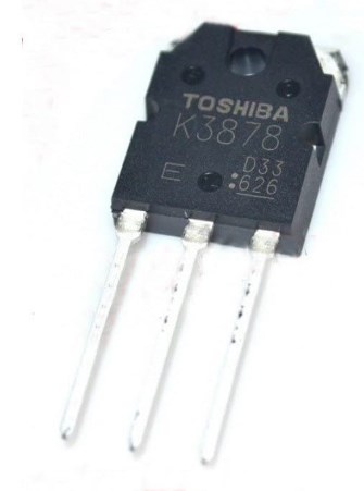 2SK3878 Field Effect Transistor: Equivalent, Datasheet and Diagram
24 February 202214293
 NRF51822 Multiprotocol Bluetooth: Schematic, Pinout, and Datasheet
24 December 20216007
 AON7403 P-Channel MOSFET: 30V 11A 8DFN, AON7403 Datasheet and Equivalents
21 February 20227071
 Advantech Corp 96MPXE-2.1-16M36: A Discontinued Skylake Microprocessor Module
11 March 20243645
 Buying the LTM8064? Read This First — Specs, Thermal Traps, and Cheaper Alternatives
23 March 2026222
 Understanding the dsPIC33EPXXXGP50X, dsPIC33EPXXXMC20X/50X, and PIC24EPXXXGP/MC20X Microcontrollers
29 February 2024188
 SN74LV1T125DCKR Single Buffer Gate: Package, Pinout, and Datasheet
15 April 20221990
 The Introduction to USB Type-C Pin Signal and PCB Layout
03 December 202126997
 What are the Types of Camera Lenses?
18 June 20212693
 What is fluorescent lamp?
19 October 20214383
 NOR Flash: Working, Structure and Applications
18 November 202114819
 Introduction to Reluctance Motor
08 March 20216212
 What are Types and Application of Gas Sensors?
18 November 202510813
 Optimizations and applications of wide-band gap (wbg) semiconductor devices for ev systems
28 October 20223585
 What is Solid-state Battery
08 March 20216211
STMicroelectronics
In Stock
United States
China
Canada
Japan
Russia
Germany
United Kingdom
Singapore
Italy
Hong Kong(China)
Taiwan(China)
France
Korea
Mexico
Netherlands
Malaysia
Austria
Spain
Switzerland
Poland
Thailand
Vietnam
India
United Arab Emirates
Afghanistan
Åland Islands
Albania
Algeria
American Samoa
Andorra
Angola
Anguilla
Antigua & Barbuda
Argentina
Armenia
Aruba
Australia
Azerbaijan
Bahamas
Bahrain
Bangladesh
Barbados
Belarus
Belgium
Belize
Benin
Bermuda
Bhutan
Bolivia
Bonaire, Sint Eustatius and Saba
Bosnia & Herzegovina
Botswana
Brazil
British Indian Ocean Territory
British Virgin Islands
Brunei
Bulgaria
Burkina Faso
Burundi
Cabo Verde
Cambodia
Cameroon
Cayman Islands
Central African Republic
Chad
Chile
Christmas Island
Cocos (Keeling) Islands
Colombia
Comoros
Congo
Congo (DRC)
Cook Islands
Costa Rica
Côte d’Ivoire
Croatia
Cuba
Curaçao
Cyprus
Czechia
Denmark
Djibouti
Dominica
Dominican Republic
Ecuador
Egypt
El Salvador
Equatorial Guinea
Eritrea
Estonia
Eswatini
Ethiopia
Falkland Islands
Faroe Islands
Fiji
Finland
French Guiana
French Polynesia
Gabon
Gambia
Georgia
Ghana
Gibraltar
Greece
Greenland
Grenada
Guadeloupe
Guam
Guatemala
Guernsey
Guinea
Guinea-Bissau
Guyana
Haiti
Honduras
Hungary
Iceland
Indonesia
Iran
Iraq
Ireland
Isle of Man
Israel
Jamaica
Jersey
Jordan
Kazakhstan
Kenya
Kiribati
Kosovo
Kuwait
Kyrgyzstan
Laos
Latvia
Lebanon
Lesotho
Liberia
Libya
Liechtenstein
Lithuania
Luxembourg
Macao(China)
Madagascar
Malawi
Maldives
Mali
Malta
Marshall Islands
Martinique
Mauritania
Mauritius
Mayotte
Micronesia
Moldova
Monaco
Mongolia
Montenegro
Montserrat
Morocco
Mozambique
Myanmar
Namibia
Nauru
Nepal
New Caledonia
New Zealand
Nicaragua
Niger
Nigeria
Niue
Norfolk Island
North Korea
North Macedonia
Northern Mariana Islands
Norway
Oman
Pakistan
Palau
Palestinian Authority
Panama
Papua New Guinea
Paraguay
Peru
Philippines
Pitcairn Islands
Portugal
Puerto Rico
Qatar
Réunion
Romania
Rwanda
Samoa
San Marino
São Tomé & Príncipe
Saudi Arabia
Senegal
Serbia
Seychelles
Sierra Leone
Sint Maarten
Slovakia
Slovenia
Solomon Islands
Somalia
South Africa
South Sudan
Sri Lanka
St Helena, Ascension, Tristan da Cunha
St. Barthélemy
St. Kitts & Nevis
St. Lucia
St. Martin
St. Pierre & Miquelon
St. Vincent & Grenadines
Sudan
Suriname
Svalbard & Jan Mayen
Sweden
Syria
Tajikistan
Tanzania
Timor-Leste
Togo
Tokelau
Tonga
Trinidad & Tobago
Tunisia
Turkey
Turkmenistan
Turks & Caicos Islands
Tuvalu
U.S. Outlying Islands
U.S. Virgin Islands
Uganda
Ukraine
Uruguay
Uzbekistan
Vanuatu
Vatican City
Venezuela
Wallis & Futuna
Yemen
Zambia
Zimbabwe
![STM32F103RBT6]() STM32F103RBT6
STM32F103RBT6STMicroelectronics
![STM32F103ZET6]() STM32F103ZET6
STM32F103ZET6STMicroelectronics
![STM32H743IIT6]() STM32H743IIT6
STM32H743IIT6STMicroelectronics
![STM32F407VET6]() STM32F407VET6
STM32F407VET6STMicroelectronics
![STM32F405RGT6]() STM32F405RGT6
STM32F405RGT6STMicroelectronics
![STM32F030C8T6]() STM32F030C8T6
STM32F030C8T6STMicroelectronics
![STM32F100C8T6B]() STM32F100C8T6B
STM32F100C8T6BSTMicroelectronics
![STM32F103VBT6]() STM32F103VBT6
STM32F103VBT6STMicroelectronics
![STM8S003F3U6TR]() STM8S003F3U6TR
STM8S003F3U6TRSTMicroelectronics
![STM32F429ZIT6]() STM32F429ZIT6
STM32F429ZIT6STMicroelectronics


