
 Product
 Brand
Brand Articles
 Tools
Tools
LM63625 Step-down Voltage Converter: Datasheet, Price, Circuit


16 Terminals LM6362 DC to DC converter IC SWITCHING REGULATOR
The LM63625 regulator is an easy-to-use, synchronous, step-down DC/DC converter designed for rugged automotive applications. This article will unlock more of its datasheet, pinout, application, circuit and more details about LM63625.
LM63625 Pinout

LM63625 Pinout
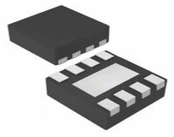
LM63625 CAD Model
Symbol

LM63625 Symbol
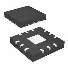
Footprint

LM63625 Footprint
3D Model

LM63625 3D Model
LM63625 Description
The LM63625 regulator is an easy-to-use, synchronous, step-down DC /DC converter designed for rugged automotive applications. The LM63625 can drive up to 1.5-A or 2.5-A of load current from an input of up to 36 V. The converter has high light load efficiency and output accuracy in a small solution size. Features such as a RESET flag and precision enable provide both flexible and easy-to-use solutions for a wide range of applications. Automatic frequency foldback at light load improves efficiency while maintaining tight load regulation. Integration eliminates many external components and provides a pinout designed for a simple PCB layout.
LM63625 Feature
• AEC-Q100-Qualified for automotive applications
– Device temperature grade 1: –40°C to +125°C
ambient operating temperature
• Functional Safety-Capable
– Documentation available to aid functional safety
system design
• Supports automotive system requirements
– Input voltage range: 3.5 V to 36 V
– Short minimum on-time of 50 ns
– Good EMI performance
Pseudo-random spread spectrum
Compatible with CISPR 25
– Low operating quiescent current of 23 µA
– Junction temperature range –40°C to +150°C
• High design flexibility
– Pin selectable VOUT: 3.3 V, 5 V, adjustable1 V to 20 V
– Pin compatible with LM63610/LM63635 (1A, 3.25 A)
– Pin selectable frequency: 400 kHz, 2.1 MHz, adjustable 250 kHz to 2200 kHz
– Pin selectable FPWM, AUTO, sync modes
– TSSOP: Thermally-enhanced package
– WSON: For space-constrained applications
• Small solution size
– As small as 10 mm x 10 mm for 2.5 A, 2.2 MHz with WSON package
– Highly integrated solution
– Low component count
LM63625 Application
• Automotive infotainment and cluster
• Automotive body electronics and lighting
• Automotive ADAS
LM63625 Alternatives
The alternatives for LM63625:
LM63610
LM63615
LM83615
LM63625 Funtional Block Diagram
The LM63625 is a synchronous peak-current-mode buck regulator that can be used in a wide range of automotive applications. Depending on the load, the regulator automatically shifts between PFM and PWM modes. The gadget switches to PWM at a consistent switching frequency when under strong load. The mode switches to PFM with diode emulation at low loads, allowing DCM. This lowers the input supply current while maintaining high efficiency. The following features are included in the device:
• Selectable output voltage
• Adjustable switching frequency
• Forced PWM mode (FPWM)
• Frequency synchronization
The RESET output makes system sequencing simple. Furthermore, compared to externally compensated regulators, internal compensation decreases design time and requires fewer external components. A functional block diagram shows below

LM63625 Functional Block Diagram
LM63625 Typical Application Circuit
A typical application circuit for the LM63625 is shown in the diagram below. This gadget is made to work with a variety of external components and system settings. Internal compensation, on the other hand, is tuned for a specific range of external inductance and output capacitance.

LM63625 Example Application Circuit VIN= 12 V; Vouτ= 5 V, louτ= 2.5 A, fsw= 2.1 MHz
LM63625 Package

LM63625 Package
Specifications
- TypeParameter
- Factory Lead Time6 Weeks
- Surface Mount
having leads that are designed to be soldered on the side of a circuit board that the body of the component is mounted on.
YES - Operating Temperature (Max.)125°C
- Operating Temperature (Min.)-40°C
- Packaging
Semiconductor package is a carrier / shell used to contain and cover one or more semiconductor components or integrated circuits. The material of the shell can be metal, plastic, glass or ceramic.
Tape & Reel (TR) - Series
In electronic components, the "Series" refers to a group of products that share similar characteristics, designs, or functionalities, often produced by the same manufacturer. These components within a series typically have common specifications but may vary in terms of voltage, power, or packaging to meet different application needs. The series name helps identify and differentiate between various product lines within a manufacturer's catalog.
Automotive, AEC-Q100 - JESD-609 Code
The "JESD-609 Code" in electronic components refers to a standardized marking code that indicates the lead-free solder composition and finish of electronic components for compliance with environmental regulations.
e4 - Pbfree Code
The "Pbfree Code" parameter in electronic components refers to the code or marking used to indicate that the component is lead-free. Lead (Pb) is a toxic substance that has been widely used in electronic components for many years, but due to environmental concerns, there has been a shift towards lead-free alternatives. The Pbfree Code helps manufacturers and users easily identify components that do not contain lead, ensuring compliance with regulations and promoting environmentally friendly practices. It is important to pay attention to the Pbfree Code when selecting electronic components to ensure they meet the necessary requirements for lead-free applications.
yes - Part Status
Parts can have many statuses as they progress through the configuration, analysis, review, and approval stages.
Active - Moisture Sensitivity Level (MSL)
Moisture Sensitivity Level (MSL) is a standardized rating that indicates the susceptibility of electronic components, particularly semiconductors, to moisture-induced damage during storage and the soldering process, defining the allowable exposure time to ambient conditions before they require special handling or baking to prevent failures
3 (168 Hours) - Number of Terminations16
- Terminal Finish
Terminal Finish refers to the surface treatment applied to the terminals or leads of electronic components to enhance their performance and longevity. It can improve solderability, corrosion resistance, and overall reliability of the connection in electronic assemblies. Common finishes include nickel, gold, and tin, each possessing distinct properties suitable for various applications. The choice of terminal finish can significantly impact the durability and effectiveness of electronic devices.
Nickel/Palladium/Gold (Ni/Pd/Au) - Additional Feature
Any Feature, including a modified Existing Feature, that is not an Existing Feature.
ALSO OPERATES IN PFM CONTROL TECHNIQUE; ADJUSTABLE OUTPUT FROM 1V TO 20V - Terminal Position
In electronic components, the term "Terminal Position" refers to the physical location of the connection points on the component where external electrical connections can be made. These connection points, known as terminals, are typically used to attach wires, leads, or other components to the main body of the electronic component. The terminal position is important for ensuring proper connectivity and functionality of the component within a circuit. It is often specified in technical datasheets or component specifications to help designers and engineers understand how to properly integrate the component into their circuit designs.
DUAL - Terminal Form
Occurring at or forming the end of a series, succession, or the like; closing; concluding.
GULL WING - Number of Functions1
- Terminal Pitch
The center distance from one pole to the next.
0.65mm - Base Part Number
The "Base Part Number" (BPN) in electronic components serves a similar purpose to the "Base Product Number." It refers to the primary identifier for a component that captures the essential characteristics shared by a group of similar components. The BPN provides a fundamental way to reference a family or series of components without specifying all the variations and specific details.
LM6362 - JESD-30 Code
JESD-30 Code refers to a standardized descriptive designation system established by JEDEC for semiconductor-device packages. This system provides a systematic method for generating designators that convey essential information about the package's physical characteristics, such as size and shape, which aids in component identification and selection. By using JESD-30 codes, manufacturers and engineers can ensure consistency and clarity in the specification of semiconductor packages across various applications and industries.
R-PDSO-G16 - Output Voltage
Output voltage is a crucial parameter in electronic components that refers to the voltage level produced by the component as a result of its operation. It represents the electrical potential difference between the output terminal of the component and a reference point, typically ground. The output voltage is a key factor in determining the performance and functionality of the component, as it dictates the level of voltage that will be delivered to the connected circuit or load. It is often specified in datasheets and technical specifications to ensure compatibility and proper functioning within a given system.
3.3V - Input Voltage-Nom
Input Voltage-Nom refers to the nominal or rated input voltage that an electronic component or device is designed to operate within. This parameter specifies the voltage level at which the component is expected to function optimally and safely. It is important to ensure that the actual input voltage supplied to the component does not exceed this nominal value to prevent damage or malfunction. Manufacturers provide this specification to guide users in selecting the appropriate power supply or input voltage source for the component. It is a critical parameter to consider when designing or using electronic circuits to ensure reliable performance and longevity of the component.
13.5V - Analog IC - Other Type
Analog IC - Other Type is a parameter used to categorize electronic components that are integrated circuits (ICs) designed for analog signal processing but do not fall into more specific subcategories such as amplifiers, comparators, or voltage regulators. These ICs may include specialized analog functions such as analog-to-digital converters (ADCs), digital-to-analog converters (DACs), voltage references, or signal conditioning circuits. They are typically used in various applications where precise analog signal processing is required, such as in audio equipment, instrumentation, communication systems, and industrial control systems. Manufacturers provide detailed specifications for these components to help engineers select the most suitable IC for their specific design requirements.
SWITCHING REGULATOR - Input Voltage (Min)
Input Voltage (Min) is a parameter in electronic components that specifies the minimum voltage level required for the component to operate properly. It indicates the lowest voltage that can be safely applied to the component without causing damage or malfunction. This parameter is crucial for ensuring the reliable and safe operation of the component within its specified operating range. It is important for designers and engineers to consider the minimum input voltage requirement when selecting and using electronic components in their circuits to prevent potential issues such as underperformance or failure.
3.5V - Control Mode
In electronic components, "Control Mode" refers to the method or mode of operation used to regulate or control the behavior of the component. This parameter determines how the component responds to input signals or commands to achieve the desired output. The control mode can vary depending on the specific component and its intended function, such as voltage regulation, current limiting, or frequency modulation. Understanding the control mode of an electronic component is crucial for proper integration and operation within a circuit or system.
CURRENT-MODE - Output Current-Max
Output Current-Max is a parameter in electronic components that specifies the maximum amount of current that can be safely drawn from the output of the component without causing damage. It is an important specification to consider when designing circuits to ensure that the component can handle the required current without overheating or failing. Exceeding the maximum output current can lead to performance issues, component damage, or even complete failure of the circuit. It is crucial to adhere to the specified maximum output current to ensure the reliable operation of the electronic component and the overall circuit.
4.41A - Input Voltage (Max)
Input Voltage (Max) refers to the maximum voltage that an electronic component can safely handle without getting damaged. This parameter is crucial for ensuring the proper functioning and longevity of the component. Exceeding the maximum input voltage can lead to overheating, electrical breakdown, or even permanent damage to the component. It is important to carefully consider and adhere to the specified maximum input voltage when designing or using electronic circuits to prevent any potential issues or failures.
36V - Control Technique
In electronic components, "Control Technique" refers to the method or approach used to regulate and manage the operation of the component. This parameter is crucial in determining how the component functions within a circuit or system. Different control techniques can include analog control, digital control, pulse-width modulation (PWM), and various feedback mechanisms. The choice of control technique can impact the performance, efficiency, and overall functionality of the electronic component. It is important to select the appropriate control technique based on the specific requirements and characteristics of the application in which the component will be used.
PULSE WIDTH MODULATION - Switcher Configuration
Switcher Configuration in electronic components refers to the arrangement or setup of a switcher circuit, which is a type of power supply that converts one form of electrical energy into another. The configuration of a switcher circuit includes the specific components used, such as transistors, diodes, capacitors, and inductors, as well as their interconnections and control mechanisms. The switcher configuration determines the efficiency, voltage regulation, and other performance characteristics of the power supply. Different switcher configurations, such as buck, boost, buck-boost, and flyback, are used for various applications depending on the desired output voltage and current requirements. Understanding and selecting the appropriate switcher configuration is crucial in designing reliable and efficient power supply systems for electronic devices.
BUCK - Switching Frequency-Max
Switching Frequency-Max is a parameter in electronic components that refers to the maximum frequency at which the device can switch on and off within a given period of time. This parameter is crucial in determining the performance and efficiency of the component, especially in applications such as power supplies, inverters, and motor drives. A higher switching frequency allows for faster operation and can result in smaller component sizes, reduced power losses, and improved overall system performance. However, it is important to consider the trade-offs between switching frequency, efficiency, and heat dissipation to ensure optimal operation of the electronic component.
2200kHz - Length5mm
- Height Seated (Max)
Height Seated (Max) is a parameter in electronic components that refers to the maximum allowable height of the component when it is properly seated or installed on a circuit board or within an enclosure. This specification is crucial for ensuring proper fit and alignment within the overall system design. Exceeding the maximum seated height can lead to mechanical interference, electrical shorts, or other issues that may impact the performance and reliability of the electronic device. Manufacturers provide this information to help designers and engineers select components that will fit within the designated space and function correctly in the intended application.
1.2mm - Width4.4mm
- RoHS Status
RoHS means “Restriction of Certain Hazardous Substances” in the “Hazardous Substances Directive” in electrical and electronic equipment.
ROHS3 Compliant
Datasheet PDF
- Datasheets :
What type of applications is the LM63625 regulator designed for?
Rugged automotive applications
How much load current can the LM63625 drive from an input of up to 36 V?
1.5-A or 2.5-A.
What type of flag does the LM63625 regulator have?
RESET flag.
What improves efficiency while maintaining tight load regulation?
Automatic frequency foldback.
What modes does the LM63625 automatically shift between?
PFM and PWM modes.
What does the LM63625 switch to when under strong load?
Lowers the input supply current while maintaining high efficiency.
What input does the LM636x5D-Q1 feature?
SYNC/MODE.
![How to Use BC547B Transistor as a Switch or an Amplifier?[ Video]](https://res.utmel.com/Images/Article/334c4527-7050-48e2-a137-ec8df881fc76.jpg) How to Use BC547B Transistor as a Switch or an Amplifier?[ Video]
How to Use BC547B Transistor as a Switch or an Amplifier?[ Video]07 April 20223680
 74HC132 Trigger: Circuit, Pinout, and Datasheet
18 December 20214392
![CR1216 3 V Battery Non-Rechargeable[Video]: Datasheet, CR1216 VS CR2016, and Equivalents](https://res.utmel.com/Images/Article/0b54a9ba-2bd8-4e1e-993a-827e6c746ece.png) CR1216 3 V Battery Non-Rechargeable[Video]: Datasheet, CR1216 VS CR2016, and Equivalents
CR1216 3 V Battery Non-Rechargeable[Video]: Datasheet, CR1216 VS CR2016, and Equivalents01 April 20224199
 ATxmega64A1U and ATxmega128A1U Microcontrollers: Technical Overview and Specifications
29 February 2024264
 TPS22965DSGT Load Switch: Layout, Pinout, and Datasheet
28 March 20224161
 HMC344LC3TR-R5 RF Switch: Pinout, Feature, Datasheet
14 August 2024473
 IRF510 Power MOSFET: Circuit, Datasheet, and Pinout
03 August 202112258
 IRLZ34N N-Channel Power MOSFET: Pinout, Equivalent and Datasheet
22 October 202112405
 How to make an Obstacle Avoiding Robot?
29 August 202315131
 Introduction to Acceleration Sensors
07 November 20258708
 How does a Photodiode Work?
15 August 202023090
 The Ultimate Guide to AI Noise Reduction Translation Earbuds
01 April 20258697
 The Complete Guide to DC-DC Converters
24 May 20252418
 Comparing Bridge Rectifiers and Full Wave Rectifiers for Beginners
09 June 202616302
 Chip Filters, Piezoelectric Materials and the Piezoelectric Effect
27 September 20226967
 Random Access Memory: Definition, Types and Working
29 August 202010499
Texas Instruments
In Stock: 4000
United States
China
Canada
Japan
Russia
Germany
United Kingdom
Singapore
Italy
Hong Kong(China)
Taiwan(China)
France
Korea
Mexico
Netherlands
Malaysia
Austria
Spain
Switzerland
Poland
Thailand
Vietnam
India
United Arab Emirates
Afghanistan
Åland Islands
Albania
Algeria
American Samoa
Andorra
Angola
Anguilla
Antigua & Barbuda
Argentina
Armenia
Aruba
Australia
Azerbaijan
Bahamas
Bahrain
Bangladesh
Barbados
Belarus
Belgium
Belize
Benin
Bermuda
Bhutan
Bolivia
Bonaire, Sint Eustatius and Saba
Bosnia & Herzegovina
Botswana
Brazil
British Indian Ocean Territory
British Virgin Islands
Brunei
Bulgaria
Burkina Faso
Burundi
Cabo Verde
Cambodia
Cameroon
Cayman Islands
Central African Republic
Chad
Chile
Christmas Island
Cocos (Keeling) Islands
Colombia
Comoros
Congo
Congo (DRC)
Cook Islands
Costa Rica
Côte d’Ivoire
Croatia
Cuba
Curaçao
Cyprus
Czechia
Denmark
Djibouti
Dominica
Dominican Republic
Ecuador
Egypt
El Salvador
Equatorial Guinea
Eritrea
Estonia
Eswatini
Ethiopia
Falkland Islands
Faroe Islands
Fiji
Finland
French Guiana
French Polynesia
Gabon
Gambia
Georgia
Ghana
Gibraltar
Greece
Greenland
Grenada
Guadeloupe
Guam
Guatemala
Guernsey
Guinea
Guinea-Bissau
Guyana
Haiti
Honduras
Hungary
Iceland
Indonesia
Iran
Iraq
Ireland
Isle of Man
Israel
Jamaica
Jersey
Jordan
Kazakhstan
Kenya
Kiribati
Kosovo
Kuwait
Kyrgyzstan
Laos
Latvia
Lebanon
Lesotho
Liberia
Libya
Liechtenstein
Lithuania
Luxembourg
Macao(China)
Madagascar
Malawi
Maldives
Mali
Malta
Marshall Islands
Martinique
Mauritania
Mauritius
Mayotte
Micronesia
Moldova
Monaco
Mongolia
Montenegro
Montserrat
Morocco
Mozambique
Myanmar
Namibia
Nauru
Nepal
New Caledonia
New Zealand
Nicaragua
Niger
Nigeria
Niue
Norfolk Island
North Korea
North Macedonia
Northern Mariana Islands
Norway
Oman
Pakistan
Palau
Palestinian Authority
Panama
Papua New Guinea
Paraguay
Peru
Philippines
Pitcairn Islands
Portugal
Puerto Rico
Qatar
Réunion
Romania
Rwanda
Samoa
San Marino
São Tomé & Príncipe
Saudi Arabia
Senegal
Serbia
Seychelles
Sierra Leone
Sint Maarten
Slovakia
Slovenia
Solomon Islands
Somalia
South Africa
South Sudan
Sri Lanka
St Helena, Ascension, Tristan da Cunha
St. Barthélemy
St. Kitts & Nevis
St. Lucia
St. Martin
St. Pierre & Miquelon
St. Vincent & Grenadines
Sudan
Suriname
Svalbard & Jan Mayen
Sweden
Syria
Tajikistan
Tanzania
Timor-Leste
Togo
Tokelau
Tonga
Trinidad & Tobago
Tunisia
Turkey
Turkmenistan
Turks & Caicos Islands
Tuvalu
U.S. Outlying Islands
U.S. Virgin Islands
Uganda
Ukraine
Uruguay
Uzbekistan
Vanuatu
Vatican City
Venezuela
Wallis & Futuna
Yemen
Zambia
Zimbabwe
![LM3485MM/NOPB]() LM3485MM/NOPB
LM3485MM/NOPBTexas Instruments
![LM3478MM/NOPB]() LM3478MM/NOPB
LM3478MM/NOPBTexas Instruments
![LM5085MY/NOPB]() LM5085MY/NOPB
LM5085MY/NOPBTexas Instruments
![UC2825DW]() UC2825DW
UC2825DWTexas Instruments
![UCC28950PWR]() UCC28950PWR
UCC28950PWRTexas Instruments
![LM3488MM/NOPB]() LM3488MM/NOPB
LM3488MM/NOPBTexas Instruments
![UC3845AD8]() UC3845AD8
UC3845AD8Texas Instruments
![LM3150MHX/NOPB]() LM3150MHX/NOPB
LM3150MHX/NOPBTexas Instruments
![UCC28C43DR]() UCC28C43DR
UCC28C43DRTexas Instruments
![UCC25600DR]() UCC25600DR
UCC25600DRTexas Instruments


