

 Product
 Brand
Brand Articles
 Tools
Tools
800G Optical Transceivers: The Guide for AI Data Centers
Quick answer
An 800G optical transceiver is a pluggable or embedded optical interface that carries an aggregate 800 Gigabits per second, but the speed label alone is not enough to specify a link. A correct deployment must match the host port, module form factor, electrical lane mode, Ethernet or breakout application, optical interface, fiber and connector, forward error correction, management revision, power class, cooling, and far-end device.
QSFP-DD and OSFP are both widely used eight-lane form-factor families for 800G-class modules. They are mechanically different and cannot be inserted into each other's native ports. QSFP-DD preserves the classic QSFP form-factor ecosystem, while OSFP provides a larger mechanical and thermal envelope. Neither is universally better: the switch platform and exact module data sheet decide compatibility.
Power and reach are product-specific. Current vendor examples span very-short-reach multimode links, 500 m parallel single-mode links, 2 km dual-400G implementations, and coherent transport modules for much longer amplified links. Do not buy an "800G" module from a generic power or distance number.
What is an 800G optical transceiver?
An optical transceiver converts electrical data from a switch, router, or network interface into modulated light and converts received light back into electrical data. At 800G, the total client or aggregate capacity is 800 Gb/s. That total may represent one 800 Gigabit Ethernet application, multiple lower-rate breakout applications, or a module that packages two independent 400G interfaces. The product description and supported application codes matter more than the number printed on the pull tab.
IEEE Std 802.3df-2024 added standardized 800 Gb/s Ethernet work. IEEE Std 802.3ck-2022 defines 100 Gb/s-per-lane electrical interfaces used by many current high-speed host-to-module designs. A common 800G host interface therefore uses eight electrical lanes at approximately 100 Gb/s per lane, but the optical side can use a different number of fibers, wavelengths, or logical applications.
This distinction prevents a common purchasing error: an eight-lane host interface does not prove that two modules have the same optical PMD, connector, reach, FEC behavior, or breakout map. For a broader introduction to transceiver terminology, see Utmel's optical transceiver selection guide.
Why use 800G in a data center?
800G links are useful where traffic engineering, switch silicon, and endpoint bandwidth justify them. AI training fabrics are an important driver because distributed accelerators exchange large east-west flows, but 800G is also relevant to cloud networks, high-performance computing, service-provider infrastructure, and data center interconnect. It is not required in every enterprise data center.
Bandwidth density
For the same number of front-panel ports, doubling each port from 400G to 800G doubles nominal aggregate port capacity. A 32-port example produces 12.8 Tb/s at 400G per port and 25.6 Tb/s at 800G per port. This is arithmetic, not a guarantee that every design can halve the number of switches. Real topology depends on radix, oversubscription, breakout requirements, redundancy, cabling, endpoints, and the capabilities of the switch ASIC.
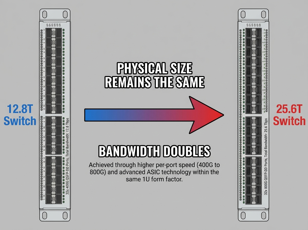
Legacy Utmel illustration retained as a 32-port arithmetic example. Verify the actual switch model, port mode, and labeling before using it for architecture decisions.
Fewer links for the same aggregate capacity
Where endpoints and topology support 800G, a design may carry the same aggregate capacity with fewer physical links than a 400G design. That can reduce connector and cable count, but the result depends on breakout strategy. An 800G port feeding eight 100G endpoints still requires an appropriate module or cable, lane mapping, and supported switch configuration.
Power per bit is a system metric
A single 800G module usually consumes more power than a lower-rate module, while energy per transmitted bit may improve in a particular platform. The useful comparison is not a generic module wattage claim. Compare the complete system at the required load: switch ASIC, SerDes, optics, fans, power conversion, cooling, fiber plant, and the number of ports needed. Vendor data sheets and measured platform power are required for a defensible conclusion.
800G form factors: QSFP-DD vs OSFP
QSFP-DD and OSFP define module, connector, cage, electrical, mechanical, management, and thermal requirements. They do not by themselves define every optical interface. An OSFP and a QSFP-DD module can be used at opposite ends of a link when both implement compatible optical specifications, but the modules cannot be swapped between native OSFP and QSFP-DD host ports.
| Decision factor | QSFP-DD | OSFP | What to verify |
|---|---|---|---|
| Host lanes | Eight high-speed electrical interfaces in the double-density family | Eight high-speed electrical interfaces in the octal family | Lane rate, application code, retiming, and host ASIC support |
| Mechanical fit | QSFP-derived module and cage | Larger OSFP module and cage | Exact switch port and supported module form factor |
| Lower-speed modules | MSA family preserves classic QSFP mechanical compatibility | Selected platforms may support QSFP modules through an adapter | Platform compatibility matrix, software, port mode, power, and cooling |
| Thermal approach | Often relies on a platform riding heat sink and cage airflow | Specifications include integrated-heat-sink and riding-heat-sink variants | Module power class, case temperature, airflow direction, altitude, and adjacent-port loading |
| 1.6T path | Current MSA revision includes QSFP-DD1600 | Current MSA revision includes OSFP1600 variants | Do not confuse form-factor support with an approved Ethernet PMD or platform qualification |
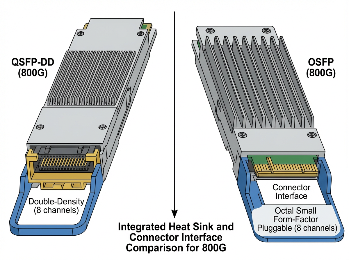
Original Utmel form-factor illustration retained for orientation. Heat-sink construction and connector details vary by MSA revision, module type, and switch platform.
Can a lower-speed module run in an 800G port?
Sometimes, but mechanical insertion is only the first condition. For example, a classic QSFP module can fit a QSFP-DD port, and selected OSFP platforms provide adapters for QSFP modules. Operation still requires a port mode supported by the switch ASIC, operating system, module, cable, power budget, and cooling design. An 800G module in a 400G port is even more conditional: the module must support the lower electrical lane rate and the host must supply enough power and cooling.
Optical interfaces, fiber, connectors, and reach
Labels such as VR, DR, FR, LR, and ZR describe different reaches or application classes, but they are not interchangeable shortcuts. The number following the suffix can indicate optical lanes or wavelengths, and a product sold as "800G" may carry one 800GE application or multiple 400GE applications. Use the complete product description and standard reference.
| Vendor example | Fiber and connector | Published reach | Selection caution |
|---|---|---|---|
| 800GBASE-VR8 OSFP | Parallel MMF, MPO | 30 m over OM3 and 50 m over OM4/OM5 in the cited Cisco portfolio | Check MPO type, APC polish, pinning, polarity, and exact platform support |
| 800GBASE-DR8 OSFP | Parallel SMF, dual MPO-12 or MPO-16 | Up to 500 m in the cited Cisco portfolio | Confirm breakout mapping, optical polarity, connector loss, and the far-end PMD |
| 2x400G-FR4 QSFP-DD or OSFP | Two duplex SMF links, dual LC | Up to 2 km in the cited Cisco portfolios | This is two 400GE applications in one module, not automatically one native 800GE PMD |
| 800ZR / 800G ZR+ | Coherent C-band or L-band SMF, LC | Cisco publishes up to 120 km amplified for 800ZR and over 1000 km for selected ZR+ modes | Reach depends on amplified line-system design, fiber loss, mode, wavelength plan, and platform support |
The examples above demonstrate why the old statement "800G reaches 50 m to 2 km" was incomplete. Data center pluggables and coherent transport modules solve different problems. The full link must align at both ends: optical PMD, wavelength, lane count, connector, fiber type, FEC, and link budget.
What is inside an 800G optical transceiver?
Module architectures vary, but a retimed 800G pluggable commonly includes high-speed host electrical interfaces, signal-conditioning or DSP functions, laser drivers and optical transmitters, photodetectors and transimpedance amplifiers, control electronics, power conversion, nonvolatile memory, thermal structures, and one or more fiber connectors.
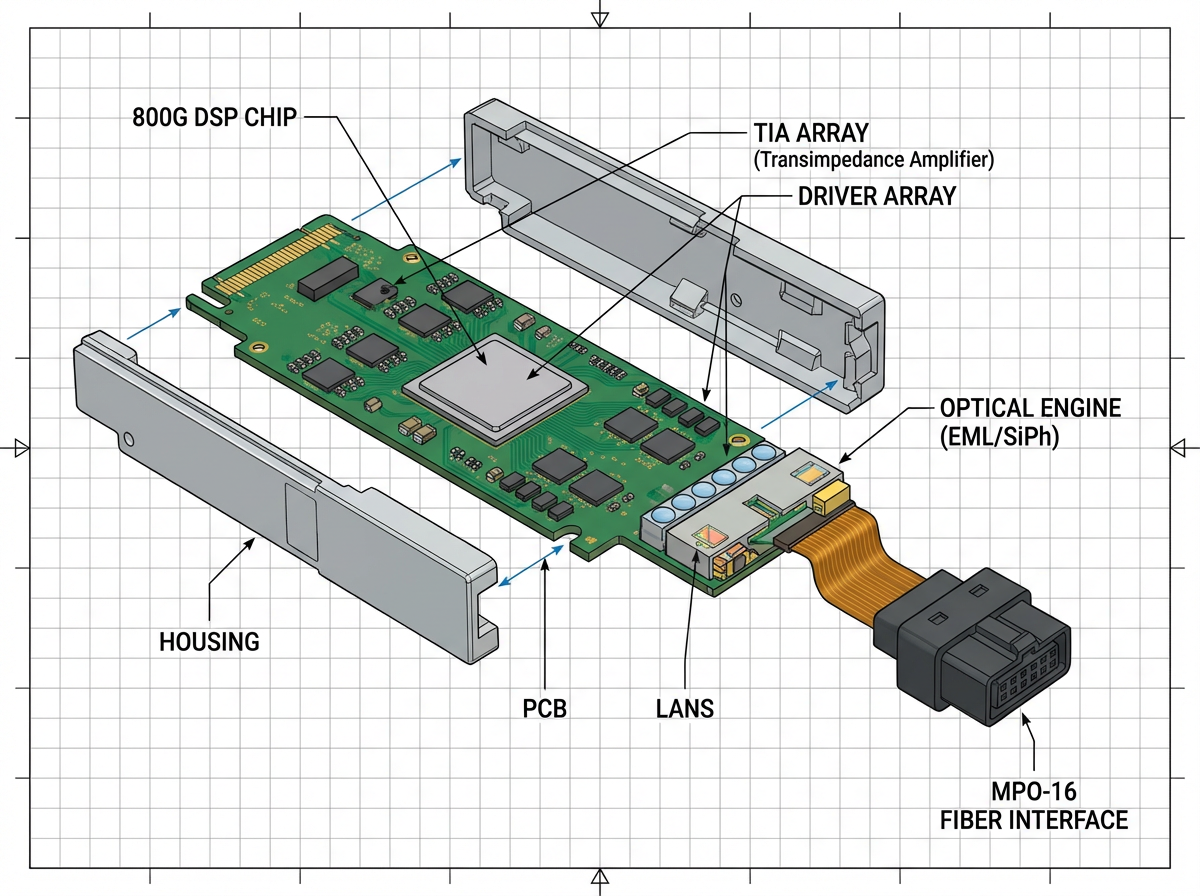
Original Utmel component illustration retained as a conceptual map. It is not a teardown of every module and does not define a universal connector, laser, or lane architecture.
Host interface and PAM4 signaling
PAM4 uses four amplitude levels and carries two bits per symbol. This increases data rate per lane but reduces the separation between signal levels compared with NRZ, so channel loss, noise, equalization, jitter, and FEC margin become critical. IEEE 802.3ck provides the 100 Gb/s-per-lane electrical foundation used by many current 800G host interfaces.
DSP, retiming, and FEC responsibilities
A retimed module DSP can recover and reshape high-speed signals, perform gearboxing or lane mapping, and support module diagnostics. Do not assume the module DSP performs every FEC function. In several current data-center optical products, Ethernet FEC is performed on the host platform. Linear pluggable optics and other lower-DSP architectures change the host-channel requirements, so a retimed-optics host design cannot be assumed to support them without platform-specific validation.
Optical transmitter
The transmit path can use directly or externally modulated lasers, silicon-photonics modulators, wavelength multiplexers, and driver electronics. EML and silicon photonics are technology categories, not universal quality rankings. The selected optical PMD, wavelength plan, reach, temperature range, and vendor implementation determine the actual architecture.
Optical receiver
The receive path typically includes photodetectors, transimpedance amplifiers, and subsequent signal conditioning. Receive power alone is not proof of a healthy link. Receiver overload, sensitivity, optical modulation amplitude, noise, lane skew, and pre-FEC error behavior also matter.
Management and telemetry
OIF CMIS defines management functions for modern multi-lane modules, including capability advertisement, application selection, module and data-path state, alarms, diagnostics, and optional firmware-related functions. CMIS 5.3 also supports richer capability and per-application power advertising. Both host and module must support compatible functions; reading an EEPROM part number is not a complete interoperability test.
Power conversion and thermal path
Power is converted locally for DSP, drivers, receivers, control logic, and optical components. Heat must travel through the module housing and heat-sink interface into chassis airflow or another cooling system. Current vendor examples show that even modules with similar headline speed can have different typical and maximum power. Coherent optics can occupy a different power class from short-reach data-center optics.
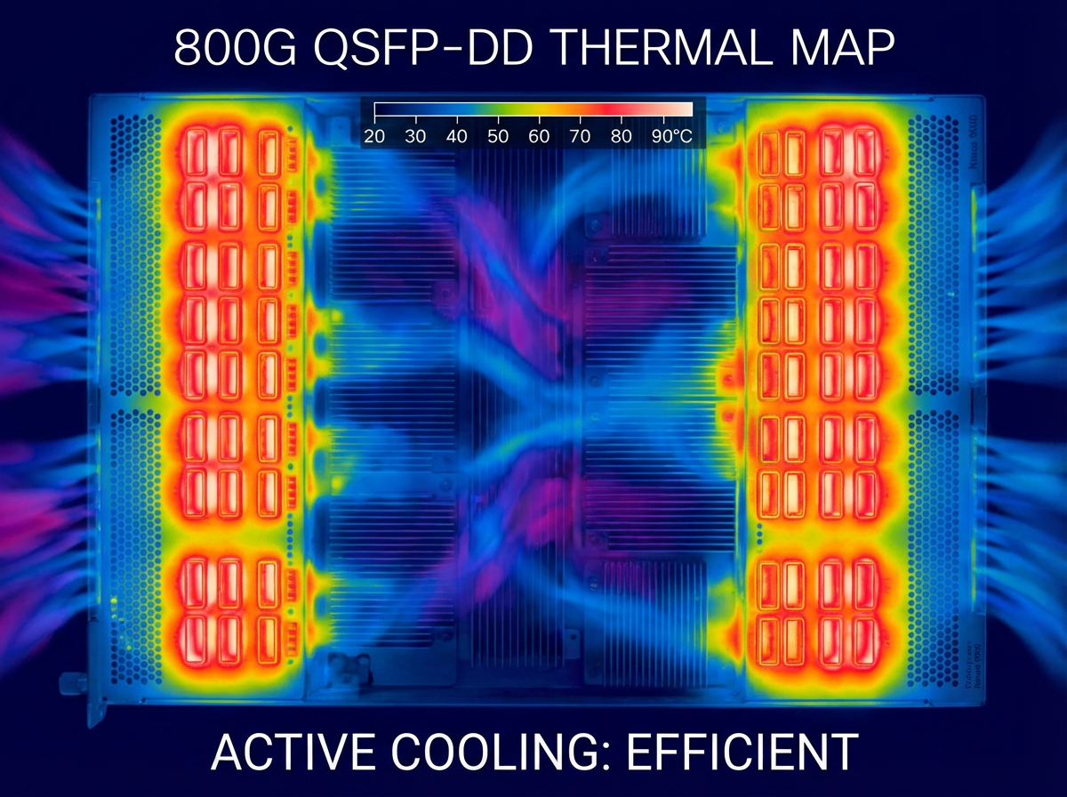
Original Utmel thermal illustration retained as a concept image, not measurement data. Do not infer a 90 C operating requirement or acceptance limit from the color scale.
800G compatibility and selection checklist
Start with the switch or router compatibility matrix and the exact module ordering code. A form-factor name or a seller's generic "compatible" label is not sufficient.
| Check | Question to answer | Evidence to collect |
|---|---|---|
| Host platform | Does the exact switch, line card, port, and software release support the module? | Vendor compatibility matrix, release notes, and port configuration guide |
| Form factor | Is the port QSFP-DD, OSFP, or another format? | Mechanical drawing, cage specification, heat-sink type, and adapter policy |
| Application and lanes | Is the requirement 800GE, 2x400GE, 4x200GE, 8x100GE, or another mode? | CMIS application advertisement, module data sheet, host lane map, and breakout guide |
| Optical PMD | Do both ends implement the same optical interface and wavelength plan? | IEEE, OIF, or MSA designation and both endpoint data sheets |
| Fiber and connector | Is the plant MMF or SMF, and are connector type, polish, pinning, and polarity correct? | Fiber records, patch-panel map, connector inspection, and loss measurements |
| FEC and interoperability | Where is FEC performed, and do both endpoints use supported settings? | Platform configuration, standard clause, FEC counters, and vendor interoperability results |
| Power and cooling | Can the port deliver the required power and keep the module within its case-temperature limit? | Maximum module power, platform thermal guide, airflow direction, altitude derating, and populated-port limits |
| Management | Which CMIS revision and firmware functions are supported? | CMIS revision, module firmware, host support notes, alarms, and application codes |
How should 800G transceivers be tested?
Acceptance testing should be tied to the exact module and platform. A basic link-up result is necessary but not sufficient, and a received-power reading inside a nominal range does not prove low error rate or adequate margin.
1. Identity and capability readback
Read the manufacturer name, part number, serial number, hardware revision, firmware revision, supported applications, power class, temperature, and alarms through the platform's management interface. Compare the electronic record with the label and purchase documentation. Vendor-specific coding should be evaluated against the host's qualification policy, not treated as proof of optical compatibility.
2. Connector inspection and cleaning
Inspect the fiber end face using equipment and procedures suitable for the connector. Confirm APC versus UPC polish, MPO pinning, key orientation, polarity, and patch-panel mapping. Contamination and polarity errors can create loss or unstable lanes that appear to be module failures.
3. Link, FEC, and traffic test
Bring up the intended application and run sustained traffic at the required load. Record pre-FEC error indicators, corrected and uncorrectable codewords, lane alarms, packet loss, and link resets. The acceptable limits must come from the platform, PMD, and module specifications. Do not invent a universal raw-BER threshold from a different interface.
4. Breakout and far-end interoperability
If the deployment uses 2x400G, 4x200G, or 8x100G, test every branch with the intended cable and endpoint. Validate lane mapping, polarity, port configuration, and independent link behavior. A module's headline breakout capability does not prove that a particular switch and NIC combination supports it.
5. Thermal validation
Measure module temperature and platform behavior with realistic adjacent-port population, fan policy, airflow direction, inlet temperature, altitude, and traffic load. Use the manufacturer's case-temperature and power limits. A generic chamber target such as 70 C is not a substitute for the exact data sheet and chassis thermal guide.
6. Firmware and recovery behavior
Verify supported firmware-upgrade procedures, rollback or recovery policy, alarm handling, and module behavior after a warm restart, cold restart, or port reconfiguration. CMIS provides standardized mechanisms, but optional functions and implementation details vary.
Procurement and incoming inspection
Availability is specific to a part number, date, quantity, source, and qualification status. The old article's broad shortage statements and fixed 24-hour shipping claim were not supported by current first-party evidence, so they have been removed. Market reports can describe demand direction, but they cannot prove that the exact module required by a project is unavailable or ready to ship.
For each quote, request the full manufacturer part number, revision, quantity, date code where applicable, source traceability, warranty terms, packaging condition, firmware status, and return procedure. Confirm whether the product is new, refurbished, pulled, programmed, vendor-coded, or third-party compatible. Those categories have different qualification and support implications.
Incoming inspection should combine documentation review, label and housing inspection, connector inspection, CMIS or EEPROM readback, host compatibility testing, traffic and FEC monitoring, and thermal checks. Visual inspection alone cannot prove authenticity or performance, and opening or repairing an optical module may void warranties and create laser-safety, ESD, contamination, calibration, and reliability risks.
When requesting sourcing support from Utmel, provide the exact module or component part number, host platform, software release, required application, reach, connector, temperature range, quantity, and target date. Availability and delivery timing should be confirmed in the current quotation rather than inferred from a general article.
From 800G to 1.6T
The transition to 1.6 Tb/s involves faster electrical lanes, new optical PMDs, higher thermal density, and evolving approaches such as retimed pluggables, linear pluggable optics, and co-packaged optics. These approaches have different host-channel, operational, serviceability, and ecosystem requirements.
As of August 2026, IEEE P802.3dj was still in standards balloting; its D3.2 second Standards Association recirculation ballot closed on August 15, 2026. Therefore, 1.6T Ethernet should be described as an active standards and product transition, not as a universally finalized Ethernet specification. Separately, current QSFP-DD and OSFP MSA documents already define 1.6T-capable form-factor variants. A mechanical roadmap is not the same as an approved PMD, shipping product, or platform qualification.
Frequently asked questions
Are 800G transceivers only used in AI data centers?
No. AI clusters are an important use case, but 800G can also serve cloud networks, high-performance computing, service-provider infrastructure, aggregation, and data center interconnect. The deployment must be justified by traffic, topology, endpoints, cost, and power.
Are QSFP-DD and OSFP interchangeable?
No. They are mechanically different host form factors. Modules at opposite ends of a fiber link can interoperate when both ends implement the same optical PMD, wavelength plan, FEC requirements, and fiber interface, but an OSFP module does not plug into a QSFP-DD port or vice versa.
Can I use a 400G or 100G module in an 800G port?
Sometimes. QSFP-DD preserves compatibility with classic QSFP form factors, and some OSFP platforms support QSFP modules through an adapter. Actual operation depends on the platform, software, port mode, module, power, cooling, and vendor qualification.
How far can an 800G transceiver reach?
There is no single reach. Current product examples range from tens of meters over multimode fiber to 500 m or 2 km over single-mode fiber, while coherent 800G modules can support much longer amplified links. Use the exact PMD and module data sheet.
How much power does an 800G transceiver consume?
Power is product-specific. Current data-center examples in the cited Cisco portfolios have typical or maximum figures in the teens of watts, while other implementations and coherent optics can occupy higher power classes. Verify the exact maximum power and platform cooling requirements.
Does an 800G module always provide one 800GE link?
No. Some modules implement one 800GE application, while others provide 2x400GE or multiple breakout applications. Confirm the CMIS application codes, product description, and host configuration.
What should be checked before buying an 800G module?
Check the host compatibility matrix, form factor, application mode, electrical lanes, optical PMD, fiber, connector, reach, FEC, CMIS revision, firmware, breakout map, power, cooling, temperature range, and far-end module.
Is 1.6T Ethernet finalized?
Not yet as of August 2026. IEEE P802.3dj was still in Standards Association recirculation ballot. Form-factor MSAs and vendor products may advance before the complete Ethernet standards process is finished.
Conclusion
The safest way to specify an 800G optical link is to treat it as a system, not a speed label. Start with the exact host and application, then align form factor, electrical lane mode, optical PMD, fiber, connector, reach, FEC, management, firmware, power, cooling, and far-end compatibility. QSFP-DD and OSFP solve different mechanical and thermal problems, but either can support robust 800G links when the platform and optical interface are correctly matched.
For procurement, replace generic availability claims with part-specific evidence and an acceptance plan. For deployment, record link, FEC, thermal, and firmware behavior under realistic load. That discipline matters more than choosing whichever module is described as "future-proof."
References
 UTMEL
UTMEL
We are the professional distributor of electronic components, providing a large variety of products to save you a lot of time, effort, and cost with our efficient self-customized service. careful order preparation fast delivery service
 Discovering New and Advanced Methodology for Determining the Dynamic Characterization of Wide Bandgap DevicesSaumitra Jagdale15 March 20242834
For a long era, silicon has stood out as the primary material for fabricating electronic devices due to its affordability, moderate efficiency, and performance capabilities. Despite its widespread use, silicon faces several limitations that render it unsuitable for applications involving high power and elevated temperatures. As technological advancements continue and the industry demands enhanced efficiency from devices, these limitations become increasingly vivid. In the quest for electronic devices that are more potent, efficient, and compact, wide bandgap materials are emerging as a dominant player. Their superiority over silicon in crucial aspects such as efficiency, higher junction temperatures, power density, thinner drift regions, and faster switching speeds positions them as the preferred materials for the future of power electronics.
Read More Applications of FPGAs in Artificial Intelligence: A Comprehensive GuideUTMEL29 August 20255478
This comprehensive guide explores FPGAs as powerful AI accelerators that offer distinct advantages over traditional GPUs and CPUs. FPGAs provide reconfigurable hardware that can be customized for specific AI workloads, delivering superior energy efficiency, ultra-low latency, and deterministic performance—particularly valuable for edge AI applications. While GPUs excel at parallel processing for training, FPGAs shine in inference tasks through their adaptability and power optimization. The document covers practical implementation challenges, including development complexity and resource constraints, while highlighting solutions like High-Level Synthesis tools and vendor-specific AI development suites from Intel and AMD/Xilinx. Real-world applications span telecommunications, healthcare, autonomous vehicles, and financial services, demonstrating FPGAs' versatility in mission-critical systems requiring real-time processing and minimal power consumption.
Read More The 2026 Engineer’s Guide: Choosing the Right MCU for Your Next IoT & New Energy ProjectUTMEL30 April 20261628
A comprehensive comparison of 2026's leading MCUs from ST, NXP, and Microchip across power efficiency, processing performance, connectivity, and ecosystems to help engineers select the optimal chip for next-gen IoT and new energy projects.
Read More AI Server Components: Engineering Next-Gen Data Center Hardware for 100kW RacksUTMEL15 May 2026890
The transition from traditional enterprise IT to AI-driven workloads has rendered legacy data center hardware obsolete, forcing infrastructure planners to re-engineer server components for extreme thermal environments.
Read More The Practical Engineer’s Guide to the NE555N Timer: Pinout, Setup, and TroubleshootingUTMEL29 May 2026676
This comprehensive guide explores the NE555N timer, detailing its 8-pin layout, internal architecture, and key datasheet specifications. It compares the bipolar IC to CMOS variants and details setup configurations for astable, monostable, and bistable modes. Additionally, the guide offers practical troubleshooting advice to prevent common breadboard failures, such as floating reset pins and electrical noise issues.
Read More
Subscribe to Utmel !
![AD8190ACPZ-R7]() AD8190ACPZ-R7
AD8190ACPZ-R7Analog Devices Inc.
![SI8235BD-D-ISR]() SI8235BD-D-ISR
SI8235BD-D-ISRSilicon Labs
![HCPL-0302-500E]() HCPL-0302-500E
HCPL-0302-500EBroadcom Limited
![ATA663231-GBQW]() ATA663231-GBQW
ATA663231-GBQWMicrochip Technology
![AD9942BBCZ]() AD9942BBCZ
AD9942BBCZAnalog Devices Inc.
![ATAES132A-SHEQ-B]() ATAES132A-SHEQ-B
ATAES132A-SHEQ-BMicrochip Technology
![ADUM7223BCCZ]() ADUM7223BCCZ
ADUM7223BCCZAnalog Devices Inc.
![FOD8332R2V]() FOD8332R2V
FOD8332R2VON Semiconductor
![FOD3180SV]() FOD3180SV
FOD3180SVON Semiconductor
![FM31L278-G]() FM31L278-G
FM31L278-GCypress Semiconductor Corp


