A brief Analysis of the 555 Timer Circuit and its Project Applications
Introduction
One well-known and versatile integrated circuit (IC) that is useful for many timing and pulse generation applications in electronics is the 555-timer circuit. Since its introduction by Signetics in 1972, the 555 timer integrated circuit (IC) has been a common element in electrical design.
Modes of 555 Timer Circuit
The 555 timers can run in monostable, bi-stable and a-stable modes. Each mode has its specific function:
· Monostable mode: A monostable circuit is similar to acting in one state (high or low) but can be forced to control the opposite state for a period controlled by a resistor-capacitor (RC) circuit. This is a schematic representation of the 555 timer in monostable mode:

555 timer pin two is kept HIGH by resistor R2, but the instantaneous it goes LOW, the period starts, and for a period, the output on pin 3 goes HIGH, ascertained by potentiometer R1 and capacitor C3. To estimate the time pin three will be HIGH then, this formula will be used:
t = 1.1 * R1 * C3
When this period ends, pin 3 becomes LOW once again. When pin 3 is HIGH, the instantaneous pin 2 goes LOW, and if pin 2 remains LOW for longer than t, pin three will remain HIGH until pin two goes HIGH once again. Monostable circuits are constructive for the cleanup of a pulse of undependable length to force it to be a notable length, like a pulse framework in a burglar alarm vibration detector or a momentary push-button circuit.
· Bi-stable mode: A bi-stable circuit has one of two states: one on and another off. Bi-stable circuits are primarily helpful in memory cells and flip-flop circuits. The schematic representation of the 555 timer setup in bi-stable mode is as follows:

It is valuable to note that if pin 2 is LOW, pin three will be HIGH on boot up.
· A-stable mode: In a-stable mode, the 555 timer plays like a square wave oscillator. A single capacitor and a variable resistor can be disciplined over a considerable frequency range. The duty cycle can also be well-adjusted. The schematic representation of the 555 timer connection in a-stable mode is:

Rresistors R1, R2, and C3 power the off and on time periods. The two time periods collectively set the frequencies of the output square wave.

In the a-stable circuit, widths can be set independently by using the two equations given below:
o Period (T) = 0.7 * (R1+2R2) * C3
o Frequency = 1/T
This will affect both the duty cycle and the pulse frequency. A 555 timer circuit consists of a resistor network, an SR flip-flop, a discharge transistor, and two voltage dividers. To fit the timing settings in accordance with the intended operation mode, external components such as resistors and capacitors are connected to the pins of the 555 timer.
To put it briefly, the 555 timer's adaptability and ease of use have led to its widespread use in a range of electronic projects and applications. It is a go-to component for professionals and students working on electronic circuits and projects because of its pinout and usability.This circuit commands an LED or any output device ON and OFF at daily time intervals. The time period between consecutive commands of LED can be attuned by the exploitation of a potentiometer.
Project: LED Flasher with 555 Timer Circuit
Here are the required components:
· 555 Timer IC
· LED or any output device
· 10uF Capacitor
· Resistors: 100K, 1K, 220R
· Breadboard
· Few Breadboard Connectors
· (5-12)V Power Supply
· Potentiometer (Optional)
· Relay Module (Optional)
Circuit Diagram
The resistors R1 and R2, with the capacitor C1, power the rate of blinking. While capacitor C1 and resistor R1 determine both the On and Off times of the LED, Resistor R2 is accountable only for the On time.
An adjustable dual LED flasher that uses a potentiometer to modify the blinking speed is shown in the circuit diagram which is given below:

· How Does This Circuit Work?
1. If the Trigger Pin (Pin-2 of the 555 timer IC) senses any voltage less than 1/3rds of the supply voltage, it turns ON the output.
2. If the Threshold Pin (Pin-6 of the 555 timer IC) senses any voltage more than 2/3rds of the supply voltage, it turns OFF the output.
3. Whenever the output of the 555 timer IC is in the OFF state, the Discharge Pin (Pin-7) acts as ground/negative rail, i.e., it is internally connected to 0V
4. Immediately after the power supply is turned on, the capacitor (C1) will be in a discharged state, and so the voltage at Pin-2 will be 0V.
5. Since this voltage is less than 1/3rds of the supply voltage, the output turns ON.
6. Simultaneously Pin-7 will internally disconnect from 0V and so the capacitor starts charging via resistors R1 & R2.
7. Immediately after the voltage across the capacitor (C1) crosses 2/3rds of the supply voltage, Pin-6 senses it and turns OFF the output.
8. Simultaneously Pin-7 will reconnect internally to 0V, which results in capacitor discharging via resistor R1.
9. And once the voltage across the capacitor falls below 1/3rd of the supply voltage, Pin-2 will turn ON the output, and this whole cycle repeats again and again.
Applications
555 timer is the most important integrated circuit (chip) used widely in digital electronics. Some common uses and applications of 555 timer IC are as follows:
· In turning indicator circuits of all types of vehicles and cycles.
· In-strobe lights / SoS signalling circuits (To signal that someone is in danger or needs help).To control wiper motors and create to-and-fro motion.
· In Light indicators used in cars (The relay version of the flashing LED circuit is used).
· As an input for applications that require timing pulses. E.g: In counter circuits using 4017 & 4026 ICs.
· PWM (Pulse Width Modulation) & PPM (Pulse Position Modulation)
· Duty Cycle Oscillator
· Lamp Dimmer
· To provide Accurate time delays
· As a flip-flop element
· Digital logic probes
· Analog frequency meters
· Quad Timer applications
· Pulse, Waveform, and square wave generation
· Stepped tone & tone burst generator & linear ramp generation
· Tachometers & temperature measurement
· It can be used as a monostable multivibrator and a-stable multivibrator
· DC to DC Converters
· DC Voltage Regulator
· Voltage to Frequency Converter
· Frequency Divider
· Schmitt trigger
· Cable tester
· Pulse detector
· Wiper speed control
· Timer Switch
· Time delay generation, precision timing and sequential timing
Conclusion
Many intriguing electronic circuits and projects use the 555 Timer IC, including the Traffic Light Circuit, LED Flashing Circuits, Police Sirens, LED Dice, Music Box, Metal Detectors, Joystick and Game Paddles, Low-Cost Line Receiver, Clap Switch Actuated Circuit, and many more.
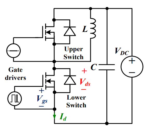
 Discovering New and Advanced Methodology for Determining the Dynamic Characterization of Wide Bandgap DevicesSaumitra Jagdale15 March 20242384
For a long era, silicon has stood out as the primary material for fabricating electronic devices due to its affordability, moderate efficiency, and performance capabilities. Despite its widespread use, silicon faces several limitations that render it unsuitable for applications involving high power and elevated temperatures. As technological advancements continue and the industry demands enhanced efficiency from devices, these limitations become increasingly vivid. In the quest for electronic devices that are more potent, efficient, and compact, wide bandgap materials are emerging as a dominant player. Their superiority over silicon in crucial aspects such as efficiency, higher junction temperatures, power density, thinner drift regions, and faster switching speeds positions them as the preferred materials for the future of power electronics.
Read More A Comprehensive Guide to FPGA Development BoardsUTMEL11 September 202510658
This comprehensive guide will take you on a journey through the fascinating world of FPGA development boards. We’ll explore what they are, how they differ from microcontrollers, and most importantly, how to choose the perfect board for your needs. Whether you’re a seasoned engineer or a curious hobbyist, prepare to unlock new possibilities in hardware design and accelerate your projects. We’ll cover everything from budget-friendly options to specialized boards for image processing, delve into popular learning paths, and even provide insights into essential software like Vivado. By the end of this article, you’ll have a clear roadmap to navigate the FPGA landscape and make informed decisions for your next groundbreaking endeavor.
Read More Applications of FPGAs in Artificial Intelligence: A Comprehensive GuideUTMEL29 August 20252698
This comprehensive guide explores FPGAs as powerful AI accelerators that offer distinct advantages over traditional GPUs and CPUs. FPGAs provide reconfigurable hardware that can be customized for specific AI workloads, delivering superior energy efficiency, ultra-low latency, and deterministic performance—particularly valuable for edge AI applications. While GPUs excel at parallel processing for training, FPGAs shine in inference tasks through their adaptability and power optimization. The document covers practical implementation challenges, including development complexity and resource constraints, while highlighting solutions like High-Level Synthesis tools and vendor-specific AI development suites from Intel and AMD/Xilinx. Real-world applications span telecommunications, healthcare, autonomous vehicles, and financial services, demonstrating FPGAs' versatility in mission-critical systems requiring real-time processing and minimal power consumption.
Read More 800G Optical Transceivers: The Guide for AI Data CentersUTMEL24 December 20251811
The complete guide to 800G Optical Transceiver standards (QSFP-DD vs. OSFP). Overcome supply shortages and scale your AI data center with Utmel Electronic.
Read More Xilinx FPGAs: From Getting Started to Advanced Application DevelopmentUTMEL09 September 20253579
This guide is your comprehensive roadmap to understanding and mastering the world of Xilinx FPGA technology. From selecting your first board to deploying advanced AI applications, we'll cover everything you need to know to unlock the potential of these remarkable devices. The global FPGA market is on a significant growth trajectory, expected to expand from USD 8.37 billion in 2025 to USD 17.53 billion by 2035. This surge is fueled by the relentless demand for high-performance, adaptable computing in everything from 5G networks and data centers to autonomous vehicles and the Internet of Things (IoT). This guide will walk you through the key concepts, tools, and products in the Xilinx ecosystem, ensuring you're well-equipped to be a part of this technological revolution.
Read More
Subscribe to Utmel !
![UCC5310MCDR]() UCC5310MCDR
UCC5310MCDRTexas Instruments
![1EDI20H12AHXUMA1]() 1EDI20H12AHXUMA1
1EDI20H12AHXUMA1Infineon Technologies
![1EDI60H12AHXUMA1]() 1EDI60H12AHXUMA1
1EDI60H12AHXUMA1Infineon Technologies
![1EDI30I12MFXUMA1]() 1EDI30I12MFXUMA1
1EDI30I12MFXUMA1Infineon Technologies
![UCC21220DR]() UCC21220DR
UCC21220DRTexas Instruments
![HCS201T-I/SN]() HCS201T-I/SN
HCS201T-I/SNMicrochip Technology
![ADATE305BSVZ]() ADATE305BSVZ
ADATE305BSVZAnalog Devices Inc.
![AD9172BBPZ]() AD9172BBPZ
AD9172BBPZAnalog Devices Inc.
![ADUM4223CRWZ]() ADUM4223CRWZ
ADUM4223CRWZAnalog Devices Inc.
![FM33256B-G]() FM33256B-G
FM33256B-GCypress Semiconductor Corp


