
 Product
 Brand
Brand Articles
 Tools
Tools
How to make an Obstacle Avoiding Robot?
ROTATING OBSTACLE AVOIDING ROBOT
Introduction
A robot that is capable of avoiding obstacles is known as an obstacle avoidance robot, and it operates autonomously. This means that when it encounters an obstacle while moving forward, it will automatically halt and take a step back. The robot then scans its surroundings to the left and right to determine the best possible route to take, either in the left direction if there is an obstacle on the right, or in the right direction if there is an obstacle on the left. To create an obstacle-avoidance robot, we will use an Arduino and an ultrasonic sensor, which will calculate the distance between the robot and any obstacles in its path. If the robot detects an obstacle, it will change its direction and continue to move.
Building obstacle avoiding robot using Ultrasonic Sensor
Prior to constructing the robot, it is crucial to comprehend the operational mechanism of the ultrasonic sensor, as it plays a vital role in detecting obstacles. The fundamental principle behind the functioning of the ultrasonic sensor involves measuring the time taken by the sensor to emit ultrasonic waves, which bounce off surfaces and are subsequently received by the sensor. Distance is then calculated by employing a formula. In this endeavor, we will be employing the HC-SR04 Ultrasonic Sensor, which is widely accessible. To use this sensor, the same methodology as explained above will be applied.

The Trig pin of the HC-SR04 is set to a high state for a minimum of 10 microseconds. This initiates the transmission of an ultrasonic wave consisting of eight pulses, each having a frequency of 40 kilohertz

The wave is then emitted and strikes a surface before being reflected back to the Echo pin of the HC-SR04, which had already been set to a high state.

The time elapsed between the transmission and reception of the signal is recorded and stored in a variable. Appropriate calculations are then employed to convert this time interval into distance. The necessary components for constructing this obstacle avoidance robot are readily available. Any toy chassis can be employed, or a custom-built one can be utilized
Components and Materials Required:
1. Arduino Uno
2. Smart robot car chassis with 2 x toy car wheels and 1 x Universal wheel (or ball casters)
3. HC-SR04 Ultrasonic Sensor
4. LM298N Motor Driver Module
5. Two DC motors
6. servo motor 9g
7. 7805 and 7812 IC
8. 7.4V 1300mah Lipo battery
9. Mounting bracket of Ultrasonic Sensor
10. Arduino Jumper wires
11. Screws and Nuts
As the official partner of Arduino, Utmel provides you with official original Arduino products. Welcome to shop at the Arduino product page.
Software Required:
· Arduino IDE
Hardware:

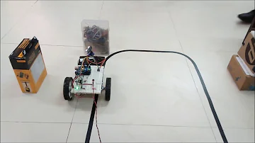
Once the circuit is ready we have to build our obstacle-avoiding car by assembling the circuit on top of a robotic chassis as shown below.
Connections
Power Supply
To operate the circuit, the Arduino UNO, servo motor, and ultrasonic sensor necessitate a regulated DC power supply of 5V, whereas the motor driver IC requires a 12V DC supply. To fulfill this requirement, a 12V NIMH battery is employed as the primary source of power. The battery's supply is controlled to produce 5V and 12V outputs utilizing 7805 and 7812 ICs, respectively. Pin 1 of both voltage regulator ICs is connected to the battery's anode, and pin 2 of both ICs is linked to the ground. The voltage outputs are then drawn from pin 3 of their corresponding regulator ICs. Furthermore, an LED connected to a 10K Ω pull-up resistor is joined between the common ground and the output pin to indicate the continuity of the supply. Despite the use of a 12V battery, the 7812 regulator IC is employed to produce a steady and regulated supply to the motor driver IC.
Ultrasonic Sensor
The ultrasonic sensor, which is situated at the front, is linked to pins A0 and A1 on the Arduino board. The sensor consists of four pins - Ground (Pin 1), Echo (Pin 2), Trigger (Pin 3), and VCC (Pin 4). The VCC and Ground pins are connected to common VCC and Ground respectively. The Echo pin of the sensor is joined to pin A1, while the Trigger pin is linked to pin A0 of the Arduino board.
Servo Motor SG-9:
The SG-9 servo motor is utilized in the project to move the ultrasonic sensor back and forth from the front to the left side, then to the right side, and finally back to the front. The servo motor comprises three terminals: VCC, Ground, and Control, with VCC and Ground being linked to a common VCC and Ground, respectively. The Control terminal of the servo motor is connected to pin 11 of the Arduino board. To shift the servo motor within the range of 0 to 180 degrees, a pulse width modulated signal is necessary. This is why the SG-9 servo motor, which can rotate within that range, is chosen for the project.
DC Motor:
There are two DC motors used for making the robotic car. The DC motors are interfaced between pins 3 and 6 and pins 14 and 11 of the motor driver IC.
The L293D motor driver IC has its pins 4, 5, 13, and 12 grounded, whereas pins 1, 16 and 9 are connected to 5V DC and pin 8 is connected to 12V DC. The pins 15, 2, 7, and 10 of the motor driver IC are connected to pins 5, 2, 3 and 4 of the Arduino board, respectively. The right wheel's DC motor is connected to pins 11 and 14 of the motor driver IC, while the left wheel's DC motor is connected to pins 3 and 6. The enable pins 1 and 9 of the motor driver IC are connected to pins 9 and 10 of the Arduino UNO.
Assembling the Chassis


Place the Arduino UNO, L298n motor driver, and servo motor on the chassis. It is essential to take note that while mounting the Arduino board, adequate space should be left to connect the USB cable, as it will be required to program the board later by linking it to the computer via USB.
If you do not understand how to build the robot on chassis you can watch YouTube videos of how to build an Arduino Chassis robot
Working
This self-governing robot operates very simply. Once the battery is attached, the robot powers on and checks for obstacles in front of it. If there are no obstacles, the robot moves forward. However, if it detects an obstacle, it stops and the servo motor rotates the ultrasonic sensor to the left (at 0 degrees) to measure the distance on the left side. Then the servo rotates the ultrasonic sensor to the right (at 180 degrees) to measure the distance on the right side. The program on the Arduino board compares the distances on the left and right sides and directs the robot to turn in the direction with the greater distance to avoid the obstacle. The robot then turns back in the opposite direction to continue moving forward.
Software
To begin, download the NewPing library file (which is a function library for the ultrasonic sensor) and paste it into the Arduino libraries folder.
Download the NewPing.rar file and extract it to the following path: C:\Arduino\libraries.
Afterward, download and open the obstacle_avoiding.ino file. Finally, connect the USB cable to the Arduino board and upload the code to the board.

Code
###
//Program to
#include <Servo.h>
#include <NewPing.h>
Servo myservo;
//define the pins to be connected to ultrasonic sensor
#define trigPin A0
#define echoPin A1
//define the pins to be connected to ultrasonic sensor
#define LeftMotor1 4
#define LeftMotor2 5
#define RightMotor1 2
#define RightMotor2 3
#define maxdist 300
#define objdist 23
NewPing sonar(trigPin, echoPin, maxdist);
int leftDistance, rightDistance;
//setup function to define the pinmodes
void setup()
{
pinMode(LeftMotor1, OUTPUT);
pinMode(LeftMotor2, OUTPUT);
pinMode(RightMotor1, OUTPUT);
pinMode(RightMotor2, OUTPUT);
pinMode(trigPin, OUTPUT);
pinMode(echoPin, INPUT);
myservo.attach(11);
myservo.write(90);
delay(1000);
}
//Loop infinite function
void loop()
{
int read_dist;
//Make servo to turn 90 degree
myservo.write(90);
delay(90);
//calling read sensor function to read the sensor data
read_dist = readsensors();
//checking the distance that is measured with the predefined value
if(read_dist < objdist)
{
//if low calling the decide path function
decide_path();
}
//calling the move forward function to move the robot forward
moveforward();
delay(500);
}
//Function to read the sensor value
int readsensors()
{
int distance;
delay(70);
//using the newping.h library function to measure the distance
unsigned int uS = sonar.ping();
distance = uS/US_ROUNDTRIP_CM;
return distance;
}
void decide_path()
{
robostop();
//rotating the servo to 3 degree to right side
myservo.write(3);
delay(500);
//calling read sensor function to measure the distance on right side
rightDistance = readsensors();
delay(500);
myservo.write(180);
delay(700);
leftDistance = readsensors();
delay(500);
myservo.write(90);
delay(100);
check_distance();
}
//function to compare the distances
void check_distance()
{
//checking whether left measured distance is lesser that right
if (leftDistance < rightDistance)
{
turnright();
}
//checking whether left measured distance is greater that right
else if (leftDistance > rightDistance)
{
turnleft();
}
else
{
turnaround();
}
}
void moveforward()
{
digitalWrite(LeftMotor1, HIGH);
digitalWrite(LeftMotor2, LOW);
digitalWrite(RightMotor1, HIGH);
digitalWrite(RightMotor2, LOW);
}
void turnleft()
{
digitalWrite(LeftMotor1, LOW);
digitalWrite(LeftMotor2, LOW);
digitalWrite(RightMotor1, HIGH);
digitalWrite(RightMotor2, LOW);
delay(350);
moveforward();
}
void turnright()
{
digitalWrite(LeftMotor1, HIGH);
digitalWrite(LeftMotor2, LOW);
digitalWrite(RightMotor1, LOW);
digitalWrite(RightMotor2, LOW);
delay(350);
moveforward();
}
void turnaround()
{
digitalWrite(LeftMotor1, LOW);
digitalWrite(LeftMotor2, HIGH);
digitalWrite(RightMotor1, HIGH);
digitalWrite(RightMotor2, LOW);
delay(700);
moveforward();
}
void robostop()
{
digitalWrite(LeftMotor1, LOW);
digitalWrite(LeftMotor2, LOW);
digitalWrite(RightMotor1, LOW);
digitalWrite(RightMotor2, LOW);
}
###
Conclusion
The obstacle avoidance robot is an extremely beneficial creation that serves as a foundation for numerous large-scale projects. It is utilized in various applications such as automated cars, robots deployed in manufacturing facilities, and even in spacecraft.
 UTMEL
UTMEL
We are the professional distributor of electronic components, providing a large variety of products to save you a lot of time, effort, and cost with our efficient self-customized service. careful order preparation fast delivery service
 IOT-Based Anti-theft HandbagUTMEL29 August 20238052
Hello everyone, welcome to the new post today. We will discuss all the security features of our Anti-theft handbag in this post.
Read More How to make an Obstacle Avoiding Robot?UTMEL29 August 202315206
The article will tell you How to make an Obstacle Avoiding Robot.
Read More Arduino and Bluetooth Based Home AutomationUTMEL29 August 20238218
Hello everyone, welcome to the new post today.
Read More Arduino Based Gas Leakage DetectionUTMEL29 August 20239481
A gas detector is a safety device that identifies the presence of gases in a particular location. It is often part of a safety system and can detect gas leaks and other emissions.
Read More Parking Access Control System using ArduinoUTMEL29 August 20236338
Hello everyone, welcome to the new post today. In this project, we will create Parking Access Control System using an RC522 RFID Module, an Arduino board, and an MG 996R Servo Motor.
Read More
Subscribe to Utmel !
![H100X044H1T-2]() H100X044H1T-2
H100X044H1T-2Panduit Corp
![ERJ-2RKF2943X]() ERJ-2RKF2943X
ERJ-2RKF2943XPanasonic Electronic Components
![ERJ-2RKF3831X]() ERJ-2RKF3831X
ERJ-2RKF3831XPanasonic Electronic Components
![83500000005]() 83500000005
83500000005Littelfuse Inc.
![BLM18SG700TN1D]() BLM18SG700TN1D
BLM18SG700TN1DMurata Electronics
![SR732ATTDR100F]() SR732ATTDR100F
SR732ATTDR100FKOA Speer Electronics, Inc.
![ERJ-2RKF6493X]() ERJ-2RKF6493X
ERJ-2RKF6493XPanasonic Electronic Components
![SR731JTTDR200F]() SR731JTTDR200F
SR731JTTDR200FKOA Speer Electronics, Inc.
![MMBZ5V6ALT1G]() MMBZ5V6ALT1G
MMBZ5V6ALT1GON Semiconductor
![EMPLUS-2GO]() EMPLUS-2GO
EMPLUS-2GOPanduit Corp


