
 Product
 Brand
Brand Articles
 Tools
Tools
DRV5053 Hall Effect Sensor: Datasheet, Pinout and Applications


Hall Effect Sensor Bipolar 3.3V/5V/9V/12V/15V/18V/24V 3-Pin SOT-23 T/R
DRV5053 is an analog-bipolar Hall Effect sensor. This article mainly covers datasheet, pinout, applications, and other details about DRV5053.

Playing with DRV5053 Linear Hall Effect Sensor and Arduino bargraph display
DRV5053 Pinout


DRV5053 CAD Model
Symbol

Footprint

3D Model

DRV5053 Description
The DRV5053 device is a chopper-stabilized Hall IC that offers a magnetic sensing solution with superior sensitivity stability over temperature and integrated protection features.
DRV5053 Functional Block Diagram

Specifications
- TypeParameter
- Lifecycle Status
Lifecycle Status refers to the current stage of an electronic component in its product life cycle, indicating whether it is active, obsolete, or transitioning between these states. An active status means the component is in production and available for purchase. An obsolete status indicates that the component is no longer being manufactured or supported, and manufacturers typically provide a limited time frame for support. Understanding the lifecycle status is crucial for design engineers to ensure continuity and reliability in their projects.
ACTIVE (Last Updated: 3 days ago) - Factory Lead Time6 Weeks
- Mount
In electronic components, the term "Mount" typically refers to the method or process of physically attaching or fixing a component onto a circuit board or other electronic device. This can involve soldering, adhesive bonding, or other techniques to secure the component in place. The mounting process is crucial for ensuring proper electrical connections and mechanical stability within the electronic system. Different components may have specific mounting requirements based on their size, shape, and function, and manufacturers provide guidelines for proper mounting procedures to ensure optimal performance and reliability of the electronic device.
Surface Mount - Mounting Type
The "Mounting Type" in electronic components refers to the method used to attach or connect a component to a circuit board or other substrate, such as through-hole, surface-mount, or panel mount.
Surface Mount - Package / Case
refers to the protective housing that encases an electronic component, providing mechanical support, electrical connections, and thermal management.
TO-236-3, SC-59, SOT-23-3 - Number of Pins3
- Operating Temperature
The operating temperature is the range of ambient temperature within which a power supply, or any other electrical equipment, operate in. This ranges from a minimum operating temperature, to a peak or maximum operating temperature, outside which, the power supply may fail.
-40°C~125°C TA - Packaging
Semiconductor package is a carrier / shell used to contain and cover one or more semiconductor components or integrated circuits. The material of the shell can be metal, plastic, glass or ceramic.
Tape & Reel (TR) - Series
In electronic components, the "Series" refers to a group of products that share similar characteristics, designs, or functionalities, often produced by the same manufacturer. These components within a series typically have common specifications but may vary in terms of voltage, power, or packaging to meet different application needs. The series name helps identify and differentiate between various product lines within a manufacturer's catalog.
Automotive, AEC-Q100 - JESD-609 Code
The "JESD-609 Code" in electronic components refers to a standardized marking code that indicates the lead-free solder composition and finish of electronic components for compliance with environmental regulations.
e4 - Pbfree Code
The "Pbfree Code" parameter in electronic components refers to the code or marking used to indicate that the component is lead-free. Lead (Pb) is a toxic substance that has been widely used in electronic components for many years, but due to environmental concerns, there has been a shift towards lead-free alternatives. The Pbfree Code helps manufacturers and users easily identify components that do not contain lead, ensuring compliance with regulations and promoting environmentally friendly practices. It is important to pay attention to the Pbfree Code when selecting electronic components to ensure they meet the necessary requirements for lead-free applications.
yes - Part Status
Parts can have many statuses as they progress through the configuration, analysis, review, and approval stages.
Active - Moisture Sensitivity Level (MSL)
Moisture Sensitivity Level (MSL) is a standardized rating that indicates the susceptibility of electronic components, particularly semiconductors, to moisture-induced damage during storage and the soldering process, defining the allowable exposure time to ambient conditions before they require special handling or baking to prevent failures
1 (Unlimited) - ECCN Code
An ECCN (Export Control Classification Number) is an alphanumeric code used by the U.S. Bureau of Industry and Security to identify and categorize electronic components and other dual-use items that may require an export license based on their technical characteristics and potential for military use.
EAR99 - Terminal Finish
Terminal Finish refers to the surface treatment applied to the terminals or leads of electronic components to enhance their performance and longevity. It can improve solderability, corrosion resistance, and overall reliability of the connection in electronic assemblies. Common finishes include nickel, gold, and tin, each possessing distinct properties suitable for various applications. The choice of terminal finish can significantly impact the durability and effectiveness of electronic devices.
Nickel/Palladium/Gold (Ni/Pd/Au) - Additional Feature
Any Feature, including a modified Existing Feature, that is not an Existing Feature.
IT HAS SENSITIVITY OF 45 MV/MT - Voltage - Supply
Voltage - Supply refers to the range of voltage levels that an electronic component or circuit is designed to operate with. It indicates the minimum and maximum supply voltage that can be applied for the device to function properly. Providing supply voltages outside this range can lead to malfunction, damage, or reduced performance. This parameter is critical for ensuring compatibility between different components in a circuit.
2.7V~38V - Base Part Number
The "Base Part Number" (BPN) in electronic components serves a similar purpose to the "Base Product Number." It refers to the primary identifier for a component that captures the essential characteristics shared by a group of similar components. The BPN provides a fundamental way to reference a family or series of components without specifying all the variations and specific details.
DRV5053 - Current - Supply (Max)
The parameter "Current - Supply (Max)" in electronic components refers to the maximum amount of current that a component can draw from a power supply for its operation. This parameter is critical for ensuring that the power supply can adequately meet the demands of the component without causing damage or malfunction. Exceeding this specified maximum current can lead to overheating, reduced performance, or failure of the component. It is essential to consider this value when designing or integrating components into electronic circuits to maintain reliability and functionality.
3.6mA - Output Type
The "Output Type" parameter in electronic components refers to the type of signal or data that is produced by the component as an output. This parameter specifies the nature of the output signal, such as analog or digital, and can also include details about the voltage levels, current levels, frequency, and other characteristics of the output signal. Understanding the output type of a component is crucial for ensuring compatibility with other components in a circuit or system, as well as for determining how the output signal can be utilized or processed further. In summary, the output type parameter provides essential information about the nature of the signal that is generated by the electronic component as its output.
Analog Voltage - Max Output Current
The maximum current that can be supplied to the load.
2.3mA - Termination Type
Termination Type in electronic components refers to the method used to connect the component to a circuit board or other electronic devices. It specifies how the component's leads or terminals are designed for soldering or mounting onto a PCB. Common termination types include through-hole, surface mount, and wire lead terminations. The termination type is an important consideration when selecting components for a circuit design, as it determines how the component will be physically connected within the circuit. Different termination types offer varying levels of durability, ease of assembly, and suitability for specific applications.
SOLDER - Output Current
The rated output current is the maximum load current that a power supply can provide at a specified ambient temperature. A power supply can never provide more current that it's rated output current unless there is a fault, such as short circuit at the load.
2.3mA - Max Supply Current
Max Supply Current refers to the maximum amount of electrical current that a component can draw from its power supply under normal operating conditions. It is a critical parameter that ensures the component operates reliably without exceeding its thermal limits or damaging internal circuitry. Exceeding this current can lead to overheating, performance degradation, or failure of the component. Understanding this parameter is essential for designing circuits that provide adequate power while avoiding overload situations.
3.6mA - Output Polarity
Output polarity in electronic components refers to the orientation of the output signal in relation to the ground or reference voltage. It indicates whether the output voltage is positive or negative with respect to the ground. Positive output polarity means the signal is higher than the ground potential, while negative output polarity signifies that the signal is lower than the ground. This characteristic is crucial for determining compatibility with other components in a circuit and ensuring proper signal processing.
COMPLEMENTARY - Linearity
In electronic components, linearity refers to the relationship between the input and output signals of the component. A component is said to be linear if its output is directly proportional to its input over a specified range. In other words, when the input signal changes, the output signal changes in a consistent and predictable manner without introducing distortion or non-linear effects.Linearity is an important parameter in electronic components such as amplifiers, filters, and sensors, as it determines the accuracy and fidelity of signal processing. Non-linearities in components can lead to signal distortion, harmonic generation, and other undesirable effects that can degrade the performance of electronic systems.Engineers often characterize the linearity of components by measuring parameters such as gain error, harmonic distortion, and intermodulation distortion. By ensuring that components exhibit good linearity characteristics, designers can create electronic systems that accurately process signals and faithfully reproduce the desired output.
1 % - Sensing Method
The sensing method in electronic components refers to the technique or mechanism used to detect and measure physical phenomena such as temperature, pressure, light, or motion. This includes a variety of technologies such as resistive, capacitive, inductive, and optical sensing methods. The choice of sensing method affects the accuracy, response time, and application suitability of the electronic component. It plays a crucial role in determining how effectively a device can interact with and interpret its environment.
Hall Effect - Housing
Housing in electronic components refers to the physical enclosure that protects the internal circuitry and components from environmental factors such as dust, moisture, and mechanical damage. It provides structural support and electrical insulation while facilitating heat dissipation. The design and materials used for housing are crucial for the reliability and performance of the electronic device, as they impact factors like thermal management, electromagnetic interference, and overall aesthetics.
PLASTIC - Sensing Range
The sensing range of position sensors is the displacement between the sensing face of the sensor and the approaching measurement object that triggers a signal change in the sensor.
±18mT - Axis
In electronic components, the parameter "Axis" typically refers to the orientation or direction along which a specific characteristic or measurement is being considered. For example, in a sensor or accelerometer, the axis may indicate the direction in which the device is measuring acceleration. In a motor or actuator, the axis may refer to the direction of movement or rotation.Understanding the axis of a component is crucial for proper installation, calibration, and operation. It helps in determining how the component will interact with other parts of a system and how its performance can be optimized. Different components may have multiple axes to consider, especially in complex systems where movement or measurements occur in multiple directions.Overall, the axis parameter provides important information about the spatial orientation or directionality of an electronic component, guiding engineers and technicians in effectively utilizing the component within a larger system.
Single - Output Range
The parameter "Output Range" in electronic components refers to the range of voltage, current, or power levels that an electronic device can provide at its output terminals. This parameter indicates the minimum and maximum values that the device can reliably produce under specified conditions. The output range is crucial for determining the suitability of a component for a particular application, ensuring that it can operate within the required parameters without exceeding limits that could lead to damage or failure.
0-2V - Features
In the context of electronic components, the term "Features" typically refers to the specific characteristics or functionalities that a particular component offers. These features can vary depending on the type of component and its intended use. For example, a microcontroller may have features such as built-in memory, analog-to-digital converters, and communication interfaces like UART or SPI.When evaluating electronic components, understanding their features is crucial in determining whether they meet the requirements of a particular project or application. Engineers and designers often look at features such as operating voltage, speed, power consumption, and communication protocols to ensure compatibility and optimal performance.In summary, the "Features" parameter in electronic components describes the unique attributes and capabilities that differentiate one component from another, helping users make informed decisions when selecting components for their electronic designs.
Temperature Compensated - Input Mode
Input mode in electronic components refers to the configuration in which a device receives signals or data from an external source. It defines how the component interacts with input signals, such as whether it is set to accept digital or analog inputs. Input mode also determines the electrical characteristics, such as impedance and voltage levels, that the device is designed to handle when processing incoming information. This setting is crucial for ensuring compatibility and proper functionality within an electronic circuit.
BIPOLAR - Height1.22mm
- Length2.92mm
- Width1.3mm
- Thickness
Thickness in electronic components refers to the measurement of how thick a particular material or layer is within the component structure. It can pertain to various aspects, such as the thickness of a substrate, a dielectric layer, or conductive traces. This parameter is crucial as it impacts the electrical, mechanical, and thermal properties of the component, influencing its performance and reliability in electronic circuits.
1mm - Radiation Hardening
Radiation hardening is the process of making electronic components and circuits resistant to damage or malfunction caused by high levels of ionizing radiation, especially for environments in outer space (especially beyond the low Earth orbit), around nuclear reactors and particle accelerators, or during nuclear accidents or nuclear warfare.
No - RoHS Status
RoHS means “Restriction of Certain Hazardous Substances” in the “Hazardous Substances Directive” in electrical and electronic equipment.
ROHS3 Compliant - Lead Free
Lead Free is a term used to describe electronic components that do not contain lead as part of their composition. Lead is a toxic material that can have harmful effects on human health and the environment, so the electronics industry has been moving towards lead-free components to reduce these risks. Lead-free components are typically made using alternative materials such as silver, copper, and tin. Manufacturers must comply with regulations such as the Restriction of Hazardous Substances (RoHS) directive to ensure that their products are lead-free and environmentally friendly.
Lead Free
DRV5053 Features
•Linear Output Hall Sensor
• Superior Temperature Stability
– Sensitivity ±10% Over Temperature
• High Sensitivity Options:
– –11 mV/mT (OA, See Figure 17)
– –23 mV/mT (PA)
– –45 mV/mT (RA)
– –90 mV/mT (VA)
– +23 mV/mT (CA)
– +45 mV/mT (EA)
• Supports a Wide Voltage Range
– 2.5 to 38 V
– No External Regulator Required
• Wide Operating Temperature Range
– TA = –40 to 125°C (Q, see Figure 17)
• Amplified Output Stage
– 2.3-mA Sink, 300 µA Source
• Output Voltage: 0.2 ~ 1.8 V
– B = 0 mT, OUT = 1 V
• Fast Power-On: 35 µs
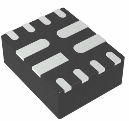
• Small Package and Footprint
– Surface Mount 3-Pin SOT-23 (DBZ)
– 2.92 mm × 2.37 mm
– Through-Hole 3-Pin TO-92 (LPG)
– 4.00 mm × 3.15 mm
• Protection Features
– Reverse Supply Protection (up to –22 V)
– Supports up to 40-V Load Dump
– Output Short-Circuit Protection
– Output Current Limitation
DRV5053 Applications
• Flow Meters
• Docking Adjustment
• Vibration Correction
• Damper Controls
DRV5053 Application Circuit

DRV5053 Alternatives

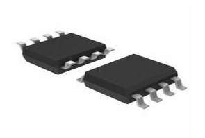
DRV5053 Package

DRV5053 Manufacturer
Texas Instruments (TI) is a global semiconductor firm originating in 1958 and nowadays it has over 30,000 employees who design, conduct, and sell analog and product-differentiating embedded processing components in 35 countries. Aimed at changing the world of tech, TI has put great effort into becoming the solution provider coupled with a vision.
Parts with Similar Specs
- ImagePart NumberManufacturerPackage / CaseNumber of PinsSensing MethodMoisture Sensitivity Level (MSL)Lead FreeWidthLengthHeightView Compare
![DRV5053EAQDBZR]()
DRV5053EAQDBZR
TO-236-3, SC-59, SOT-23-3
3
Hall Effect
1 (Unlimited)
Lead Free
1.3 mm
2.92 mm
1.22 mm
![DRV5013AGQDBZR]()
TO-236-3, SC-59, SOT-23-3
3
Hall Effect
1 (Unlimited)
Lead Free
1.3 mm
2.92 mm
1.22 mm
![DRV5053RAQDBZR]()
TO-236-3, SC-59, SOT-23-3
3
Hall Effect
1 (Unlimited)
Lead Free
1.3 mm
2.92 mm
1.22 mm
![DRV5033AJQDBZR]()
TO-236-3, SC-59, SOT-23-3
3
Hall Effect
1 (Unlimited)
Lead Free
1.3 mm
2.92 mm
1.22 mm

Datasheet PDF
- Datasheets :
- PCN Assembly/Origin :
Trend Analysis
What is DRV5053 used for?
The DRV5053 device is a chopper-stabilized Hall IC that offers a magnetic sensing solution with superior sensitivity stability over temperature and integrated protection features.
How does DRV5053 work?
DRV5053 Hall Effect sensors work by measuring the charging voltage when the device is placed in a magnetic field. In other words, once a Hall Effect sensor detects that it is now in a magnetic field, it is able to sense the position of objects.
![MB10F Bridge Stack: Features, Pinout, and Datasheet [Video&FAQ]](https://res.utmel.com/Images/Article/be2ec37f-a7df-40ce-9d94-173c34202fdf.png) MB10F Bridge Stack: Features, Pinout, and Datasheet [Video&FAQ]
MB10F Bridge Stack: Features, Pinout, and Datasheet [Video&FAQ]08 October 202124368
 TPS2121RUXR Power Multiplexers: 12-VFQFN, Pinout, Datasheet
07 March 20224713
![RP2040 VS ESP32 VS STM32[Video]: What are the differences between them?](https://res.utmel.com/Images/Article/ad58040c-0c1d-4c58-8f0d-b08b81599e64.png) RP2040 VS ESP32 VS STM32[Video]: What are the differences between them?
RP2040 VS ESP32 VS STM32[Video]: What are the differences between them?18 April 20225177
 LM301A Operational Amplifier: Pinout, Features and Datasheet
08 November 20211622
 VHR-3N Rectangular Connector: JST VHR-3N, Equivalent, Datasheet
17 March 20222246
 Unveiling the Microchip PIC24HJ32GP302/304 Microcontroller Series: A Technical Deep Dive
29 February 2024165
 AD8307 92 dB Logarithmic Amplifier: Datasheet, Pinout, and RF Power Measurement Analysis
12 February 2026252
 CR2016 vs. CR2032: Specifications, Applications, Differences
04 November 202185864
 What is a Variable Resistor?
26 April 202527730
 Semiconductor Equipment Is in Short Supply
14 March 20223613
 The Art of Microchips: A Journey from Sand to Silicon
12 September 20233842
 Facial Recognition: Features, Working and Applications
02 September 20218985
 Why are TWS Earbuds so Popular?
17 July 20216388
 Advanced Aircraft Power Electronics Systems and Influence of Simulation, Standards, and Wide Band-Gap Devices
18 February 20242502
 How does the CPU Calculate 1+1?
12 January 20224306
 An Overview of Digital Signal Processor
31 October 20259387
Texas Instruments
In Stock: 50321
United States
China
Canada
Japan
Russia
Germany
United Kingdom
Singapore
Italy
Hong Kong(China)
Taiwan(China)
France
Korea
Mexico
Netherlands
Malaysia
Austria
Spain
Switzerland
Poland
Thailand
Vietnam
India
United Arab Emirates
Afghanistan
Åland Islands
Albania
Algeria
American Samoa
Andorra
Angola
Anguilla
Antigua & Barbuda
Argentina
Armenia
Aruba
Australia
Azerbaijan
Bahamas
Bahrain
Bangladesh
Barbados
Belarus
Belgium
Belize
Benin
Bermuda
Bhutan
Bolivia
Bonaire, Sint Eustatius and Saba
Bosnia & Herzegovina
Botswana
Brazil
British Indian Ocean Territory
British Virgin Islands
Brunei
Bulgaria
Burkina Faso
Burundi
Cabo Verde
Cambodia
Cameroon
Cayman Islands
Central African Republic
Chad
Chile
Christmas Island
Cocos (Keeling) Islands
Colombia
Comoros
Congo
Congo (DRC)
Cook Islands
Costa Rica
Côte d’Ivoire
Croatia
Cuba
Curaçao
Cyprus
Czechia
Denmark
Djibouti
Dominica
Dominican Republic
Ecuador
Egypt
El Salvador
Equatorial Guinea
Eritrea
Estonia
Eswatini
Ethiopia
Falkland Islands
Faroe Islands
Fiji
Finland
French Guiana
French Polynesia
Gabon
Gambia
Georgia
Ghana
Gibraltar
Greece
Greenland
Grenada
Guadeloupe
Guam
Guatemala
Guernsey
Guinea
Guinea-Bissau
Guyana
Haiti
Honduras
Hungary
Iceland
Indonesia
Iran
Iraq
Ireland
Isle of Man
Israel
Jamaica
Jersey
Jordan
Kazakhstan
Kenya
Kiribati
Kosovo
Kuwait
Kyrgyzstan
Laos
Latvia
Lebanon
Lesotho
Liberia
Libya
Liechtenstein
Lithuania
Luxembourg
Macao(China)
Madagascar
Malawi
Maldives
Mali
Malta
Marshall Islands
Martinique
Mauritania
Mauritius
Mayotte
Micronesia
Moldova
Monaco
Mongolia
Montenegro
Montserrat
Morocco
Mozambique
Myanmar
Namibia
Nauru
Nepal
New Caledonia
New Zealand
Nicaragua
Niger
Nigeria
Niue
Norfolk Island
North Korea
North Macedonia
Northern Mariana Islands
Norway
Oman
Pakistan
Palau
Palestinian Authority
Panama
Papua New Guinea
Paraguay
Peru
Philippines
Pitcairn Islands
Portugal
Puerto Rico
Qatar
Réunion
Romania
Rwanda
Samoa
San Marino
São Tomé & Príncipe
Saudi Arabia
Senegal
Serbia
Seychelles
Sierra Leone
Sint Maarten
Slovakia
Slovenia
Solomon Islands
Somalia
South Africa
South Sudan
Sri Lanka
St Helena, Ascension, Tristan da Cunha
St. Barthélemy
St. Kitts & Nevis
St. Lucia
St. Martin
St. Pierre & Miquelon
St. Vincent & Grenadines
Sudan
Suriname
Svalbard & Jan Mayen
Sweden
Syria
Tajikistan
Tanzania
Timor-Leste
Togo
Tokelau
Tonga
Trinidad & Tobago
Tunisia
Turkey
Turkmenistan
Turks & Caicos Islands
Tuvalu
U.S. Outlying Islands
U.S. Virgin Islands
Uganda
Ukraine
Uruguay
Uzbekistan
Vanuatu
Vatican City
Venezuela
Wallis & Futuna
Yemen
Zambia
Zimbabwe
![DRV5053VAQDBZR]() DRV5053VAQDBZR
DRV5053VAQDBZRTexas Instruments
![DRV5053VAQLPG]() DRV5053VAQLPG
DRV5053VAQLPGTexas Instruments
![DRV5053CAQDBZR]() DRV5053CAQDBZR
DRV5053CAQDBZRTexas Instruments
![DRV5053OAQDBZR]() DRV5053OAQDBZR
DRV5053OAQDBZRTexas Instruments
![DRV5053RAQDBZR]() DRV5053RAQDBZR
DRV5053RAQDBZRTexas Instruments
![DRV5055A2QDBZR]() DRV5055A2QDBZR
DRV5055A2QDBZRTexas Instruments
![DRV5053VAQDBZT]() DRV5053VAQDBZT
DRV5053VAQDBZTTexas Instruments
![DRV425RTJT]() DRV425RTJT
DRV425RTJTTexas Instruments
![DRV5053EAQDBZRQ1]() DRV5053EAQDBZRQ1
DRV5053EAQDBZRQ1Texas Instruments


