
 Product
 Brand
Brand Articles
 Tools
Tools
LTM8061EV-4.2#PBF PMIC Battery Charger: A Comprehensive Technical Overview

Linear Technology/Analog Devices
Constant - Programmable LTM8061 77-BLGA Tray µModule® Series 77 Terminals 77 Pin
Unit Price: $14.846193
Ext Price: $14.85


Constant - Programmable LTM8061 77-BLGA Tray µModule® Series 77 Terminals 77 Pin
This article provides a detailed technical analysis of the LTM8061EV-4.2#PBF, a PMIC battery charger manufactured by Linear Technology/Analog Devices. It covers the product description, features, applications, reference designs, alternative parts, and FAQs related to this advanced battery charging solution.
Product Introduction
Description:
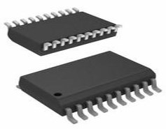
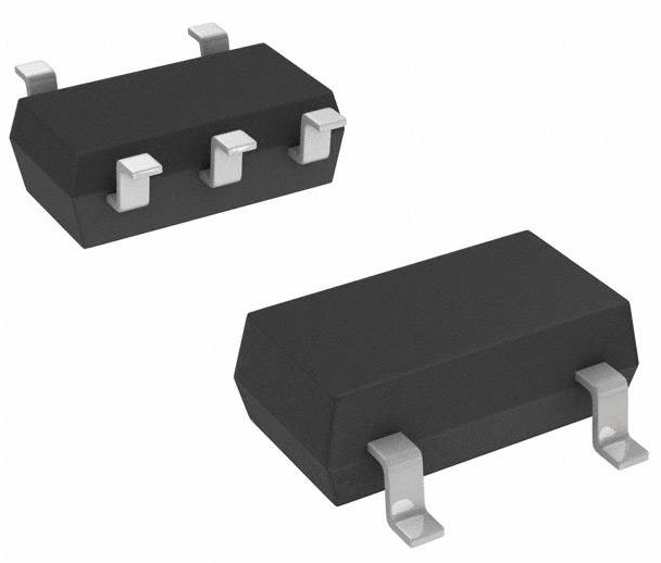
The LTM8061EV-4.2#PBF is a high-performance PMIC battery charger designed for lithium-ion/polymer battery packs. It operates in a current-mode control configuration with a programmable charge current of up to 2A. The device supports a wide input voltage range from 4.95V to 32V, making it suitable for a variety of applications. With its compact 77-BLGA package and µModule® design, the LTM8061EV-4.2#PBF offers a highly integrated solution for battery charging requirements.
Features:
- Current-mode control for precise charging
- Programmable charge current and timer
- Wide input voltage range (4.95V to 32V)
- Compact and integrated µModule® design
- High maximum charge current of 2A
- RoHS3 compliant and environmentally friendly
Applications:
Primary Applications:
1. Portable electronic devices
2. Smartphones and tablets
3. Wearable devices
4. Portable medical devices
Secondary Applications:
1. Industrial handheld equipment
2. Portable instrumentation
3. Battery-powered IoT devices
4. Portable audio and multimedia devices
Applicable Specific Modules:
1. Battery management systems
2. Power banks
3. Portable chargers
4. Energy harvesting systems
Reference Designs:
1. Portable Power Charger Reference Design
2. Wearable Device Battery Management Reference Design
3. IoT Sensor Node Power Management Reference Design
Alternative Parts:
1. LTM8062EV-4.2#PBF PMIC Battery Charger
2. LTM8060EV-4.2#PBF PMIC Battery Charger
3. LTM8063EV-4.2#PBF PMIC Battery Charger
FAQs:
Q1: What is the maximum charge current supported by the LTM8061EV-4.2#PBF?
A1: The LTM8061EV-4.2#PBF can provide a maximum charge current of 2A, allowing for fast and efficient battery charging.
Q2: Is the LTM8061EV-4.2#PBF suitable for lithium-ion and lithium-polymer battery packs?
A2: Yes, the LTM8061EV-4.2#PBF is specifically designed for lithium-ion/polymer battery chemistry, ensuring compatibility with these common battery types.
Q3: Can the charge current and timer be programmed in the LTM8061EV-4.2#PBF?
A3: Yes, the LTM8061EV-4.2#PBF features programmable charge current and timer settings, providing flexibility in charging parameters based on the application requirements.
In conclusion, the LTM8061EV-4.2#PBF PMIC battery charger offers a versatile and high-performance solution for charging lithium-ion/polymer battery packs in a wide range of portable and handheld electronic devices. Its advanced features, compact design, and wide input voltage range make it an ideal choice for various applications requiring efficient and reliable battery charging.
Specifications
- TypeParameter
- Factory Lead Time12 Weeks
- Mounting Type
The "Mounting Type" in electronic components refers to the method used to attach or connect a component to a circuit board or other substrate, such as through-hole, surface-mount, or panel mount.
Surface Mount - Surface Mount
having leads that are designed to be soldered on the side of a circuit board that the body of the component is mounted on.
YES - Package / Case
refers to the protective housing that encases an electronic component, providing mechanical support, electrical connections, and thermal management.
77-BLGA - Series
In electronic components, the "Series" refers to a group of products that share similar characteristics, designs, or functionalities, often produced by the same manufacturer. These components within a series typically have common specifications but may vary in terms of voltage, power, or packaging to meet different application needs. The series name helps identify and differentiate between various product lines within a manufacturer's catalog.
µModule® - Packaging
Semiconductor package is a carrier / shell used to contain and cover one or more semiconductor components or integrated circuits. The material of the shell can be metal, plastic, glass or ceramic.
Tray - Operating Temperature
The operating temperature is the range of ambient temperature within which a power supply, or any other electrical equipment, operate in. This ranges from a minimum operating temperature, to a peak or maximum operating temperature, outside which, the power supply may fail.
0°C~125°C TA - JESD-609 Code
The "JESD-609 Code" in electronic components refers to a standardized marking code that indicates the lead-free solder composition and finish of electronic components for compliance with environmental regulations.
e4 - Part Status
Parts can have many statuses as they progress through the configuration, analysis, review, and approval stages.
Active - Moisture Sensitivity Level (MSL)
Moisture Sensitivity Level (MSL) is a standardized rating that indicates the susceptibility of electronic components, particularly semiconductors, to moisture-induced damage during storage and the soldering process, defining the allowable exposure time to ambient conditions before they require special handling or baking to prevent failures
3 (168 Hours) - Number of Terminations77
- ECCN Code
An ECCN (Export Control Classification Number) is an alphanumeric code used by the U.S. Bureau of Industry and Security to identify and categorize electronic components and other dual-use items that may require an export license based on their technical characteristics and potential for military use.
EAR99 - Terminal Finish
Terminal Finish refers to the surface treatment applied to the terminals or leads of electronic components to enhance their performance and longevity. It can improve solderability, corrosion resistance, and overall reliability of the connection in electronic assemblies. Common finishes include nickel, gold, and tin, each possessing distinct properties suitable for various applications. The choice of terminal finish can significantly impact the durability and effectiveness of electronic devices.
Gold (Au) - Terminal Position
In electronic components, the term "Terminal Position" refers to the physical location of the connection points on the component where external electrical connections can be made. These connection points, known as terminals, are typically used to attach wires, leads, or other components to the main body of the electronic component. The terminal position is important for ensuring proper connectivity and functionality of the component within a circuit. It is often specified in technical datasheets or component specifications to help designers and engineers understand how to properly integrate the component into their circuit designs.
BOTTOM - Terminal Form
Occurring at or forming the end of a series, succession, or the like; closing; concluding.
BUTT - Peak Reflow Temperature (Cel)
Peak Reflow Temperature (Cel) is a parameter that specifies the maximum temperature at which an electronic component can be exposed during the reflow soldering process. Reflow soldering is a common method used to attach electronic components to a circuit board. The Peak Reflow Temperature is crucial because it ensures that the component is not damaged or degraded during the soldering process. Exceeding the specified Peak Reflow Temperature can lead to issues such as component failure, reduced performance, or even permanent damage to the component. It is important for manufacturers and assemblers to adhere to the recommended Peak Reflow Temperature to ensure the reliability and functionality of the electronic components.
245 - Number of Functions1
- Time@Peak Reflow Temperature-Max (s)
Time@Peak Reflow Temperature-Max (s) refers to the maximum duration that an electronic component can be exposed to the peak reflow temperature during the soldering process, which is crucial for ensuring reliable solder joint formation without damaging the component.
30 - Base Part Number
The "Base Part Number" (BPN) in electronic components serves a similar purpose to the "Base Product Number." It refers to the primary identifier for a component that captures the essential characteristics shared by a group of similar components. The BPN provides a fundamental way to reference a family or series of components without specifying all the variations and specific details.
LTM8061 - Pin Count
a count of all of the component leads (or pins)
77 - JESD-30 Code
JESD-30 Code refers to a standardized descriptive designation system established by JEDEC for semiconductor-device packages. This system provides a systematic method for generating designators that convey essential information about the package's physical characteristics, such as size and shape, which aids in component identification and selection. By using JESD-30 codes, manufacturers and engineers can ensure consistency and clarity in the specification of semiconductor packages across various applications and industries.
R-PBGA-B77 - Qualification Status
An indicator of formal certification of qualifications.
Not Qualified - Analog IC - Other Type
Analog IC - Other Type is a parameter used to categorize electronic components that are integrated circuits (ICs) designed for analog signal processing but do not fall into more specific subcategories such as amplifiers, comparators, or voltage regulators. These ICs may include specialized analog functions such as analog-to-digital converters (ADCs), digital-to-analog converters (DACs), voltage references, or signal conditioning circuits. They are typically used in various applications where precise analog signal processing is required, such as in audio equipment, instrumentation, communication systems, and industrial control systems. Manufacturers provide detailed specifications for these components to help engineers select the most suitable IC for their specific design requirements.
BATTERY CHARGE CONTROLLER - Input Voltage (Min)
Input Voltage (Min) is a parameter in electronic components that specifies the minimum voltage level required for the component to operate properly. It indicates the lowest voltage that can be safely applied to the component without causing damage or malfunction. This parameter is crucial for ensuring the reliable and safe operation of the component within its specified operating range. It is important for designers and engineers to consider the minimum input voltage requirement when selecting and using electronic components in their circuits to prevent potential issues such as underperformance or failure.
4.95V - Control Mode
In electronic components, "Control Mode" refers to the method or mode of operation used to regulate or control the behavior of the component. This parameter determines how the component responds to input signals or commands to achieve the desired output. The control mode can vary depending on the specific component and its intended function, such as voltage regulation, current limiting, or frequency modulation. Understanding the control mode of an electronic component is crucial for proper integration and operation within a circuit or system.
CURRENT-MODE - Input Voltage (Max)
Input Voltage (Max) refers to the maximum voltage that an electronic component can safely handle without getting damaged. This parameter is crucial for ensuring the proper functioning and longevity of the component. Exceeding the maximum input voltage can lead to overheating, electrical breakdown, or even permanent damage to the component. It is important to carefully consider and adhere to the specified maximum input voltage when designing or using electronic circuits to prevent any potential issues or failures.
32V - Switcher Configuration
Switcher Configuration in electronic components refers to the arrangement or setup of a switcher circuit, which is a type of power supply that converts one form of electrical energy into another. The configuration of a switcher circuit includes the specific components used, such as transistors, diodes, capacitors, and inductors, as well as their interconnections and control mechanisms. The switcher configuration determines the efficiency, voltage regulation, and other performance characteristics of the power supply. Different switcher configurations, such as buck, boost, buck-boost, and flyback, are used for various applications depending on the desired output voltage and current requirements. Understanding and selecting the appropriate switcher configuration is crucial in designing reliable and efficient power supply systems for electronic devices.
BUCK - Battery Chemistry
A battery is a device that stores chemical energy, and converts it to electricity. This is known as electrochemistry and the system that underpins a battery is called an electrochemical cell. A battery can be made up of one or several (like in Volta's original pile) electrochemical cells.
Lithium Ion/Polymer - Number of Cells1
- Voltage - Supply (Max)
Voltage - Supply (Max) is a parameter in electronic components that specifies the maximum voltage that can be safely applied to the component for proper operation. This parameter is crucial for ensuring the component's longevity and preventing damage due to overvoltage conditions. Exceeding the maximum supply voltage can lead to component failure, reduced performance, or even permanent damage. Designers must carefully consider this parameter when selecting components and designing circuits to ensure reliable and safe operation within the specified voltage limits.
32V - Programmable Features
Some of the features that characterize programmable automation are:High investment in general-purpose equipment; Low production rates relative to fixed automation; Flexibility to deal with changes in product configuration; and Most suitable for batch production.
Current, Timer - Current - Charging
Current - Charging refers to the flow of electric charge supplied to a rechargeable battery or capacitor during the charging process. It represents the amount of current that is delivered to the energy storage device to replenish its energy. This parameter is critical in determining how quickly a device can be charged and must be managed to ensure safety and longevity of the component. Overcharging or supplying excessive current can lead to overheating or damage, making it essential to adhere to specified charging currents for optimal performance.
Constant - Programmable - Charge Current - Max
Charge Current - Max is the maximum amount of current that can safely flow into a battery or capacitor during the charging process. It is a crucial parameter that helps prevent overheating and damage to the component. Exceeding this current during charging can lead to reduced performance, shortened lifespan, or even failure of the electronic component. This parameter should be adhered to for safe and effective operation of the device.
2A - Battery Pack Voltage
A battery pack is a set of any number of (preferably) identical batteries or individual battery cells. They may be configured in a series, parallel or a mixture of both to deliver the desired voltage, capacity, or power density. The term battery pack is often used in reference to cordless tools, radio-controlled hobby toys, and battery electric vehicles.
4.2V - Height Seated (Max)
Height Seated (Max) is a parameter in electronic components that refers to the maximum allowable height of the component when it is properly seated or installed on a circuit board or within an enclosure. This specification is crucial for ensuring proper fit and alignment within the overall system design. Exceeding the maximum seated height can lead to mechanical interference, electrical shorts, or other issues that may impact the performance and reliability of the electronic device. Manufacturers provide this information to help designers and engineers select components that will fit within the designated space and function correctly in the intended application.
4.42mm - Width9mm
- RoHS Status
RoHS means “Restriction of Certain Hazardous Substances” in the “Hazardous Substances Directive” in electrical and electronic equipment.
ROHS3 Compliant
Parts with Similar Specs
Datasheet PDF
- Datasheets :
- PCN Assembly/Origin :
- PCN Design/Specification :
- Simulation Models :
 MCP2200 Converter: Features, Pinout, and Datasheet
24 November 20212414
 AD8397 310mA High-Output Op-Amp: Performance Analysis and PCB Layout Handbook
14 March 2026210
 AD7291 ADC Design Notes: Resolving I2C Arbitration, Temperature Stability, and Driver Bugs
06 May 2026146
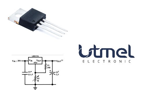 LM317AT-Linear Voltage Regulators 3-TERMINAL ADJ REG
26 February 20221359
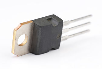 onsemi MJE15032G Review for Advanced Frequency Applications
08 September 2025344
 AD9364BBCZ RF Transceiver ICs: Package,Datasheet,Specification
14 May 20212772
 NC7SZ125P5X: Overview, Features, and Applications
19 December 20231119
 D882 Transistor: NPN Medium Power Transistor, Pinout, Equivalent, Uses
13 January 202254861
 HF PCB Circuit Design 10 Questions
16 March 20225348
 Diode Basis: Symbol, Types and Applications
09 January 202614706
 Introduction to Pi Filter
19 February 202115802
 SiC MOSFET Shortage 2026: Supply, Lead Times & Alternatives
02 July 2026199
 What is Cat 7 Cable?
04 January 20228161
 Basic Knowledge of Various Types of Mixers
03 January 20236512
 The Ultimate Guide to Microchip MCUs: From Selection to Real-World Applications
13 September 20251354
 What Is a Decoupling Capacitor? Function, Placement, and Selection Guide
04 July 202613378
Linear Technology/Analog Devices
In Stock: 12
Minimum: 1 Multiples: 1
Qty
Unit Price
Ext Price
1
$14.846193
$14.85
10
$14.005843
$140.06
100
$13.213059
$1,321.31
500
$12.465150
$6,232.58
1000
$11.759575
$11,759.58
Not the price you want? Send RFQ Now and we'll contact you ASAP.
Inquire for More Quantity
![LTC4010CFE#PBF]() LTC4010CFE#PBF
LTC4010CFE#PBFLinear Technology/Analog Devices
![LTC1760CFW#PBF]() LTC1760CFW#PBF
LTC1760CFW#PBFLinear Technology/Analog Devices
![LTC4020EUHF#TRPBF]() LTC4020EUHF#TRPBF
LTC4020EUHF#TRPBFLinear Technology/Analog Devices
![LT3652IMSE#PBF]() LT3652IMSE#PBF
LT3652IMSE#PBFLinear Technology/Analog Devices
![LTC4006EGN-4#PBF]() LTC4006EGN-4#PBF
LTC4006EGN-4#PBFLinear Technology/Analog Devices
![LTC4020EUHF#PBF]() LTC4020EUHF#PBF
LTC4020EUHF#PBFLinear Technology/Analog Devices
![LT3652IDD#PBF]() LT3652IDD#PBF
LT3652IDD#PBFLinear Technology/Analog Devices
![LT3650EDD-8.2#PBF]() LT3650EDD-8.2#PBF
LT3650EDD-8.2#PBFLinear Technology/Analog Devices
![LTC1760CFW#TRPBF]() LTC1760CFW#TRPBF
LTC1760CFW#TRPBFLinear Technology/Analog Devices
![LTC3110EUF#PBF]() LTC3110EUF#PBF
LTC3110EUF#PBFLinear Technology/Analog Devices


