MAX232ACSE Driver/Receiver: Features, Pinout, and Datasheet
16 Terminations 5V 16 Pin MAX232 Receivers 2/2 Drivers/Receivers 2 Functions
Unit Price: $2.395058
Ext Price: $2.40


16 Terminations 5V 16 Pin MAX232 Receivers 2/2 Drivers/Receivers 2 Functions
The MAX232ACSE is a multichannel, +5V-powered RS-232 driver/receiver. This article mainly introduces features, pinout, datasheet and other detailed information about Maxim Integrated MAX232ACSE.
MAX232ACSE Description
The MAX232ACSE is a multichannel, +5V-powered RS-232 driver/receiver. The MAX220-MAX249 line driver/receiver family is designed for all EIA/TIA-232E and V.28/V.24 communications interfaces, especially where ±12V is not available.
The MAX225, MAX233, MAX235, and MAX245/MAX246/MAX247 don't have any external components and are ideal for applications where board space is limited. The MAX220-MAX249 is available in 26 distinct packages, ranging from 0 to +70°C to -55°C to +125°C.
MAX232ACSE Pinout
The following figure shows the Pinout of MAX232ACSE.
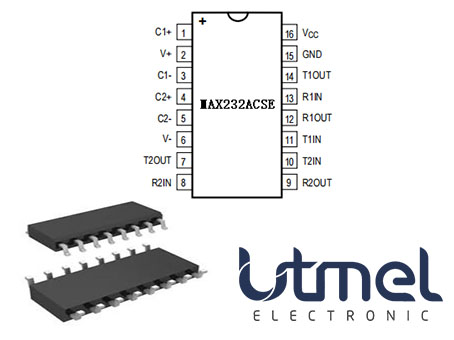
Pinout
MAX232ACSE CAD Model
The MAX232ACSE Symbol, Footprint and 3D Model are shown as follows.
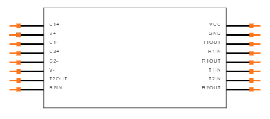
Symbol
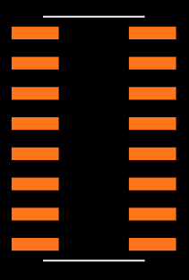
Footprint
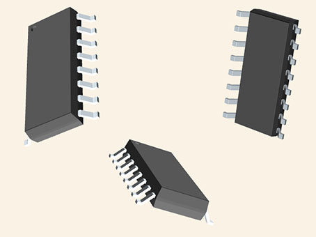
3D Model
MAX232ACSE Features
Saves Board Space
• Integrated Charge Pump Circuitry
-Eliminates the Need for a Bipolar ±12V Supply
-Enables Single-Supply Operation from +5V Supply
• Integrated Capacitors (MAX223, MAX233, MAX235, MAX245–MAX247)
Saves Power for Reduced Power Requirements
• 5μW Shutdown Mode
Specifications
- TypeParameter
- Factory Lead Time6 Weeks
- Contact Plating
Contact plating (finish) provides corrosion protection for base metals and optimizes the mechanical and electrical properties of the contact interfaces.
Tin - Mount
In electronic components, the term "Mount" typically refers to the method or process of physically attaching or fixing a component onto a circuit board or other electronic device. This can involve soldering, adhesive bonding, or other techniques to secure the component in place. The mounting process is crucial for ensuring proper electrical connections and mechanical stability within the electronic system. Different components may have specific mounting requirements based on their size, shape, and function, and manufacturers provide guidelines for proper mounting procedures to ensure optimal performance and reliability of the electronic device.
Surface Mount - Mounting Type
The "Mounting Type" in electronic components refers to the method used to attach or connect a component to a circuit board or other substrate, such as through-hole, surface-mount, or panel mount.
Surface Mount - Package / Case
refers to the protective housing that encases an electronic component, providing mechanical support, electrical connections, and thermal management.
16-SOIC (0.154, 3.90mm Width) - Number of Pins16
- Weight547.485991mg
- Operating Temperature
The operating temperature is the range of ambient temperature within which a power supply, or any other electrical equipment, operate in. This ranges from a minimum operating temperature, to a peak or maximum operating temperature, outside which, the power supply may fail.
0°C~70°C - Packaging
Semiconductor package is a carrier / shell used to contain and cover one or more semiconductor components or integrated circuits. The material of the shell can be metal, plastic, glass or ceramic.
Tube - Published2006
- JESD-609 Code
The "JESD-609 Code" in electronic components refers to a standardized marking code that indicates the lead-free solder composition and finish of electronic components for compliance with environmental regulations.
e3 - Pbfree Code
The "Pbfree Code" parameter in electronic components refers to the code or marking used to indicate that the component is lead-free. Lead (Pb) is a toxic substance that has been widely used in electronic components for many years, but due to environmental concerns, there has been a shift towards lead-free alternatives. The Pbfree Code helps manufacturers and users easily identify components that do not contain lead, ensuring compliance with regulations and promoting environmentally friendly practices. It is important to pay attention to the Pbfree Code when selecting electronic components to ensure they meet the necessary requirements for lead-free applications.
yes - Part Status
Parts can have many statuses as they progress through the configuration, analysis, review, and approval stages.
Active - Moisture Sensitivity Level (MSL)
Moisture Sensitivity Level (MSL) is a standardized rating that indicates the susceptibility of electronic components, particularly semiconductors, to moisture-induced damage during storage and the soldering process, defining the allowable exposure time to ambient conditions before they require special handling or baking to prevent failures
1 (Unlimited) - Number of Terminations16
- ECCN Code
An ECCN (Export Control Classification Number) is an alphanumeric code used by the U.S. Bureau of Industry and Security to identify and categorize electronic components and other dual-use items that may require an export license based on their technical characteristics and potential for military use.
EAR99 - TypeTransceiver
- Additional Feature
Any Feature, including a modified Existing Feature, that is not an Existing Feature.
EXTERNAL CHARGE PUMP - Voltage - Supply
Voltage - Supply refers to the range of voltage levels that an electronic component or circuit is designed to operate with. It indicates the minimum and maximum supply voltage that can be applied for the device to function properly. Providing supply voltages outside this range can lead to malfunction, damage, or reduced performance. This parameter is critical for ensuring compatibility between different components in a circuit.
4.5V~5.5V - Terminal Position
In electronic components, the term "Terminal Position" refers to the physical location of the connection points on the component where external electrical connections can be made. These connection points, known as terminals, are typically used to attach wires, leads, or other components to the main body of the electronic component. The terminal position is important for ensuring proper connectivity and functionality of the component within a circuit. It is often specified in technical datasheets or component specifications to help designers and engineers understand how to properly integrate the component into their circuit designs.
DUAL - Terminal Form
Occurring at or forming the end of a series, succession, or the like; closing; concluding.
GULL WING - Peak Reflow Temperature (Cel)
Peak Reflow Temperature (Cel) is a parameter that specifies the maximum temperature at which an electronic component can be exposed during the reflow soldering process. Reflow soldering is a common method used to attach electronic components to a circuit board. The Peak Reflow Temperature is crucial because it ensures that the component is not damaged or degraded during the soldering process. Exceeding the specified Peak Reflow Temperature can lead to issues such as component failure, reduced performance, or even permanent damage to the component. It is important for manufacturers and assemblers to adhere to the recommended Peak Reflow Temperature to ensure the reliability and functionality of the electronic components.
260 - Number of Functions2
- Supply Voltage
Supply voltage refers to the electrical potential difference provided to an electronic component or circuit. It is crucial for the proper operation of devices, as it powers their functions and determines performance characteristics. The supply voltage must be within specified limits to ensure reliability and prevent damage to components. Different electronic devices have specific supply voltage requirements, which can vary widely depending on their design and intended application.
5V - Time@Peak Reflow Temperature-Max (s)
Time@Peak Reflow Temperature-Max (s) refers to the maximum duration that an electronic component can be exposed to the peak reflow temperature during the soldering process, which is crucial for ensuring reliable solder joint formation without damaging the component.
30 - Base Part Number
The "Base Part Number" (BPN) in electronic components serves a similar purpose to the "Base Product Number." It refers to the primary identifier for a component that captures the essential characteristics shared by a group of similar components. The BPN provides a fundamental way to reference a family or series of components without specifying all the variations and specific details.
MAX232 - Pin Count
a count of all of the component leads (or pins)
16 - Operating Supply Voltage
The voltage level by which an electrical system is designated and to which certain operating characteristics of the system are related.
5V - Power Supplies
an electronic circuit that converts the voltage of an alternating current (AC) into a direct current (DC) voltage.?
5V - Voltage
Voltage is a measure of the electric potential difference between two points in an electrical circuit. It is typically represented by the symbol "V" and is measured in volts. Voltage is a crucial parameter in electronic components as it determines the flow of electric current through a circuit. It is responsible for driving the movement of electrons from one point to another, providing the energy needed for electronic devices to function properly. In summary, voltage is a fundamental concept in electronics that plays a key role in the operation and performance of electronic components.
5V - Interface
In electronic components, the term "Interface" refers to the point at which two different systems, devices, or components connect and interact with each other. It can involve physical connections such as ports, connectors, or cables, as well as communication protocols and standards that facilitate the exchange of data or signals between the connected entities. The interface serves as a bridge that enables seamless communication and interoperability between different parts of a system or between different systems altogether. Designing a reliable and efficient interface is crucial in ensuring proper functionality and performance of electronic components and systems.
RS-232 - Operating Supply Current
Operating Supply Current, also known as supply current or quiescent current, is a crucial parameter in electronic components that indicates the amount of current required for the device to operate under normal conditions. It represents the current drawn by the component from the power supply while it is functioning. This parameter is important for determining the power consumption of the component and is typically specified in datasheets to help designers calculate the overall power requirements of their circuits. Understanding the operating supply current is essential for ensuring proper functionality and efficiency of electronic systems.
10mA - Nominal Supply Current
Nominal current is the same as the rated current. It is the current drawn by the motor while delivering rated mechanical output at its shaft.
4μA - Power Dissipation
the process by which an electronic or electrical device produces heat (energy loss or waste) as an undesirable derivative of its primary action.
842mW - Propagation Delay
the flight time of packets over the transmission link and is limited by the speed of light.
1 μs - Logic Function
In electronic components, the term "Logic Function" refers to the specific operation or behavior of a component based on its input signals. It describes how the component processes the input signals to produce the desired output. Logic functions are fundamental to digital circuits and are used to perform logical operations such as AND, OR, NOT, and XOR.Each electronic component, such as logic gates or flip-flops, is designed to perform a specific logic function based on its internal circuitry. By understanding the logic function of a component, engineers can design and analyze complex digital systems to ensure proper functionality and performance. Different logic functions can be combined to create more complex operations, allowing for the creation of sophisticated digital devices and systems.
Receiver, Transceiver - Data Rate
Data Rate is defined as the amount of data transmitted during a specified time period over a network. It is the speed at which data is transferred from one device to another or between a peripheral device and the computer. It is generally measured in Mega bits per second(Mbps) or Mega bytes per second(MBps).
200kbps - Output Characteristics
Output characteristics in electronic components refer to the relationship between the output voltage and output current across a range of input conditions. This parameter is essential for understanding how a device, such as a transistor or operational amplifier, behaves under various loads and operating points. It provides insights into the efficiency, performance, and limitations of the component, helping designers to make informed choices for circuits and applications.
TOTEM-POLE - Differential Output
a differential output voltage in electronics is the difference between the values of two AC voltages, 180° out of phase, present at the output terminals of an amplifier when you apply a differential input voltage to the input terminals of an amplifier.
NO - Output Polarity
Output polarity in electronic components refers to the orientation of the output signal in relation to the ground or reference voltage. It indicates whether the output voltage is positive or negative with respect to the ground. Positive output polarity means the signal is higher than the ground potential, while negative output polarity signifies that the signal is lower than the ground. This characteristic is crucial for determining compatibility with other components in a circuit and ensuring proper signal processing.
INVERTED - Protocol
In electronic components, the parameter "Protocol" refers to a set of rules and standards that govern the communication between devices. It defines the format, timing, sequencing, and error checking methods for data exchange between different components or systems. Protocols ensure that devices can understand and interpret data correctly, enabling them to communicate effectively with each other. Common examples of protocols in electronics include USB, Ethernet, SPI, I2C, and Bluetooth, each with its own specifications for data transmission. Understanding and adhering to protocols is essential for ensuring compatibility and reliable communication between electronic devices.
RS232 - Input Characteristics
In electronic components, "Input Characteristics" refer to the set of specifications that describe how the component behaves in response to signals or inputs applied to it. These characteristics typically include parameters such as input voltage, input current, input impedance, input capacitance, and input frequency range. Understanding the input characteristics of a component is crucial for designing circuits and systems, as it helps ensure compatibility and proper functioning. By analyzing these parameters, engineers can determine how the component will interact with the signals it receives and make informed decisions about its use in a particular application.
SCHMITT TRIGGER - Number of Drivers/Receivers2/2
- Receiver Number of Bits2
- Duplex
In the context of electronic components, "Duplex" refers to a type of communication system that allows for bidirectional data flow. It enables two devices to communicate with each other simultaneously, allowing for both sending and receiving of data at the same time. Duplex communication can be further categorized into two types: half-duplex, where data can be transmitted in both directions but not at the same time, and full-duplex, where data can be sent and received simultaneously. This parameter is crucial in networking and telecommunications systems to ensure efficient and effective data transmission between devices.
Full - Receiver Hysteresis
Receiver hysteresis is?commonly used to ensure glitch-free reception even when differential noise is present. This application report compares the noise immunity of the SN65HVD37 to similar devices available from competitors. Contents.
500mV - Number of Drivers2
- Number of Transceivers1
- Simplex/Duplex
In electronic components, the parameter "Simplex/Duplex" refers to the type of communication or data transmission mode supported by the component. Simplex communication is a one-way communication mode where data flows only in one direction, from the sender to the receiver. This means that the sender can only transmit data, and the receiver can only receive data. On the other hand, duplex communication is a two-way communication mode where data can flow in both directions, allowing for simultaneous transmission and reception of data between two devices. Understanding whether a component supports simplex or duplex communication is important for determining how data will be exchanged between devices and ensuring compatibility in a given system.
Full Duplex - Transmit Delay-Max
Transmit Delay-Max refers to the maximum time interval it takes for a signal to be transmitted from the input to the output of an electronic component or system. This parameter is critical in digital circuits and communication systems, as it affects the overall performance and timing of data transmission. A lower Transmit Delay-Max indicates faster signal propagation, which is essential for high-speed applications. It is typically specified in nanoseconds or microseconds, depending on the technology and design of the component.
3500 ns - High Level Input Current-Max
High Level Input Current-Max is a parameter in electronic components that specifies the maximum current that can be safely input to the device when the input signal is at a high logic level. This parameter is important for ensuring that the component operates within its specified limits and does not get damaged due to excessive current flow. It is typically measured in milliamperes (mA) and helps in determining the compatibility of the component with the input signal source. Designers and engineers use this parameter to select components that can handle the expected input current levels without malfunctioning.
0.00004A - Height1.75mm
- Length10mm
- Width4mm
- REACH SVHC
The parameter "REACH SVHC" in electronic components refers to the compliance with the Registration, Evaluation, Authorization, and Restriction of Chemicals (REACH) regulation regarding Substances of Very High Concern (SVHC). SVHCs are substances that may have serious effects on human health or the environment, and their use is regulated under REACH to ensure their safe handling and minimize their impact.Manufacturers of electronic components need to declare if their products contain any SVHCs above a certain threshold concentration and provide information on the safe use of these substances. This information allows customers to make informed decisions about the potential risks associated with using the components and take appropriate measures to mitigate any hazards.Ensuring compliance with REACH SVHC requirements is essential for electronics manufacturers to meet regulatory standards, protect human health and the environment, and maintain transparency in their supply chain. It also demonstrates a commitment to sustainability and responsible manufacturing practices in the electronics industry.
No SVHC - Radiation Hardening
Radiation hardening is the process of making electronic components and circuits resistant to damage or malfunction caused by high levels of ionizing radiation, especially for environments in outer space (especially beyond the low Earth orbit), around nuclear reactors and particle accelerators, or during nuclear accidents or nuclear warfare.
No - RoHS Status
RoHS means “Restriction of Certain Hazardous Substances” in the “Hazardous Substances Directive” in electrical and electronic equipment.
ROHS3 Compliant - Lead Free
Lead Free is a term used to describe electronic components that do not contain lead as part of their composition. Lead is a toxic material that can have harmful effects on human health and the environment, so the electronics industry has been moving towards lead-free components to reduce these risks. Lead-free components are typically made using alternative materials such as silver, copper, and tin. Manufacturers must comply with regulations such as the Restriction of Hazardous Substances (RoHS) directive to ensure that their products are lead-free and environmentally friendly.
Lead Free
MAX232ACSE Typical Operating Circuit
The following figure shows the MAX232ACSE Typical Operating Circuit.
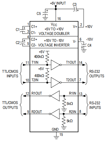
Typical Operating Circuit
MAX232ACSE Alternatives
| Part Number | Decription | Manufacturer |
| MAX232AEWEDRIVERS AND INTERFACES | Line Transceiver, 2 Func, 2 Driver, 2 Rcvr, CMOS, PDSO16, SOP-16 | Maxim Integrated Products |
| 5962-9456502MVADRIVERS AND INTERFACES | Line Transceiver, 2 Func, 2 Driver, 2 Rcvr, CMOS, CDIP18, CERDIP-18 | Defense Logistics Agency |
| MAX222IDWDRIVERS AND INTERFACES | 5-V dual channel 200kbps RS-232 line driver/receiver with +/-9V output & +/-15-kV ESD protection 18-SOIC -40 to 85 | Texas Instruments |
| MAX242CAP+TDRIVERS AND INTERFACES | Line Transceiver, 2 Func, 2 Driver, 2 Rcvr, CMOS, PDSO20, SSOP-20 | Maxim Integrated Products |
| MAX232AEWE+DRIVERS AND INTERFACES | Line Transceiver, 2 Func, 2 Driver, 2 Rcvr, CMOS, PDSO16, ROHS COMPLIANT, SOP-16 | Maxim Integrated Products |
| MAX222CNDRIVERS AND INTERFACES | 5-V Dual RS-232 Line Driver/Receiver with +/-15 kV ESD Protection 18-PDIP 0 to 70 | Texas Instruments |
| MAX232AESEDRIVERS AND INTERFACES | Line Transceiver, 2 Func, 2 Driver, 2 Rcvr, CMOS, PDSO16, SOP-16 | Rochester Electronics LLC |
| MAX242EPN+DRIVERS AND INTERFACES | Line Transceiver, 2 Func, 2 Driver, 2 Rcvr, CMOS, PDIP18, ROHS COMPLIANT, PLASTIC, DIP-18 | Maxim Integrated Products |
| MAX222EWNDRIVERS AND INTERFACES | Line Transceiver, 2 Func, 2 Driver, 2 Rcvr, CMOS, PDSO18, SOP-18 | Maxim Integrated Products |
| MAX222EWN+TDRIVERS AND INTERFACES | Line Transceiver, 2 Func, 2 Driver, 2 Rcvr, CMOS, PDSO18, ROHS COMPLIANT, SOP-18 | Maxim Integrated Products |
MAX232ACSE Applications
• Interface Translation
• Multidrop RS-232 Networks
• Portable Diagnostics Equipment
• Communications & Networking
• Portable Devices
• Medical
MAX232ACSE Manufacturer
Maxim Integrated, a subsidiary of Analog Devices , designs, manufactures and sells analog and mixed-signal integrated circuits for automotive, industrial, communications, consumer, and computing applications. Power and battery management ICs, sensors, analog ICs, interface ICs, communications solutions, digital ICs, embedded security, and microcontrollers are all part of Maxim's product line. The company includes design centers, manufacturing facilities, and sales offices all around the world, with its headquarters in San Jose , California.
Trend Analysis
Datasheet PDF
- Datasheets :
- Application Notes :
- ConflictMineralStatement :
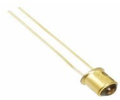 OP132 Hermetic Infrared Diode: Datasheet, Specifications and Applications
03 August 20211334
 tsop38238 IR Receiver Sensor
26 March 20225504
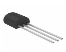 BC183 Bipolar NPN Transistor: 30V, 01A, TO92, BC183 Transistor Pinout and Equivalent
12 January 20222689
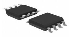 M24C16-R EEPROM: Pinout, Equivalent and Datasheet
18 December 20211505
 DA221TL Diode: Datasheet, Pinout, Inner Circuit
22 September 2021428
 MJE13009 NPN Power Transistor: Datasheet, Pinout and Circuit
25 October 20219308
 TPS22918DBVR On-Resistance Load Switch: Layout, Pinout, and Datasheet
07 April 20222861
 DS1302 RTC: Pinout, Datasheet, Circuit
05 August 20216070
 Semiconductor Market Predicted to Witness Significant Growth by 2023
19 September 20231813
 Introduction to Distribution Transformer
24 February 20217361
 Top 10 OSAT (Outsourced Semiconductor Assembly and Test) Companies
18 December 202555658
 Semiconductor Veteran Kevin Conley Takes Helm as CEO of Applied Brain Research
13 September 20232197
 Semiconductor Material Industry Guide
21 January 20225342
 The Historical Milestones of Coaxial Cable Development
19 July 20251459
 Is there a Limit to the Chip Process Node?
02 November 202118329
 The Role of SiC in Extended Space Missions
20 September 20242021
Maxim Integrated
In Stock: 1000
Minimum: 1 Multiples: 1
Qty
Unit Price
Ext Price
1
$2.395058
$2.40
10
$2.259489
$22.59
100
$2.131593
$213.16
500
$2.010937
$1,005.47
1000
$1.897110
$1,897.11
Not the price you want? Send RFQ Now and we'll contact you ASAP.
Inquire for More Quantity


