
 Product
 Brand
Brand Articles
 Tools
Tools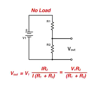

Voltage Divider Calculator Overview
The Voltage Divider Calculator determines the output voltage of a resistor divider from the input voltage and resistor values. It can also account for a load resistance connected from the output node to ground, helping users compare the ideal unloaded result with the actual loaded output.
A two-resistor voltage divider is useful for scaling a voltage to a lower level, setting bias points, sensing battery or supply voltage, creating reference thresholds, and adapting signals for analog inputs. It is best suited to high-impedance loads. A divider is not a voltage regulator and usually should not be used as a power supply for a load whose current changes.
Voltage Divider Circuit
A basic voltage divider uses two resistors in series across an input voltage. R1 is the upper resistor connected to the input, and R2 is the lower resistor connected to ground. The output voltage is measured at the junction of R1 and R2 relative to ground.

Calculator Inputs
| Input | Meaning | Typical Unit |
|---|---|---|
| Vin | The voltage applied across the complete divider. | V |
| R1 | The upper resistor between Vin and the output node. | Ω, kΩ, MΩ |
| R2 | The lower resistor between the output node and ground. | Ω, kΩ, MΩ |
| RL | An optional load resistance connected from the output node to ground. | Ω, kΩ, MΩ |
Calculator Outputs
| Output | Meaning |
|---|---|
| Output voltage | The voltage at the junction of R1 and R2, including the effect of RL when entered. |
| Divider current | The current through the unloaded series divider. |
| Divider ratio | The fraction of the input voltage that appears at the output. |
| Equivalent output resistance | The Thevenin resistance seen by a load connected to the output. |
Unloaded Voltage Divider Formula
When no significant load is connected to the output, the same current flows through R1 and R2. The output voltage is:
Vout = Vin × R2 / (R1 + R2)
The divider ratio is:
K = Vout / Vin = R2 / (R1 + R2)
Because R1 and R2 are positive resistance values, the output of this passive divider is between 0 V and Vin when referenced to the same ground.
Deriving the Voltage Divider Equation
The total resistance of the unloaded series circuit is R1 + R2. Using Ohm's law, the divider current is:
I = Vin / (R1 + R2)
The output is the voltage across R2:
Vout = I × R2
Substituting the current expression gives:
Vout = Vin × R2 / (R1 + R2)
Unloaded Voltage Divider Example
Suppose Vin = 5 V, R1 = 1 kΩ, and R2 = 2 kΩ:
Vout = 5 × 2000 / (1000 + 2000)
Vout = 3.333 V
The original calculation must use 1000 + 2000 in the denominator. Dividing one resistor by the other in the denominator would produce an incorrect result.
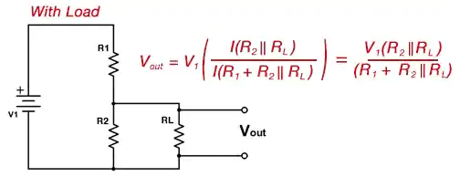
Loaded Voltage Divider Formula
A connected load draws current from the output node. If the load resistance RL is connected in parallel with R2, first calculate the effective lower resistance:
REQ = R2 × RL / (R2 + RL)
Then calculate the loaded output voltage:
Vout = Vin × REQ / (R1 + REQ)
The effective lower resistance is always smaller than either parallel resistance. Therefore, a finite load connected in parallel with R2 lowers the output voltage compared with the unloaded result.
Loaded Divider Example
Continue with Vin = 5 V, R1 = 1 kΩ, and R2 = 2 kΩ, then connect a 10 kΩ load:
REQ = 2000 × 10000 / (2000 + 10000) = 1666.7 Ω
Vout = 5 × 1666.7 / (1000 + 1666.7) = 3.125 V
The unloaded output is 3.333 V, but the 10 kΩ load reduces it to 3.125 V. This difference is the loading error.
Thevenin Equivalent of a Voltage Divider
From the output node, an ideal two-resistor divider can be represented by a Thevenin voltage and resistance:
VTH = Vin × R2 / (R1 + R2)
RTH = R1 × R2 / (R1 + R2)
With a load connected, the output can also be calculated as:
Vout = VTH × RL / (RTH + RL)
The Thevenin form makes the design tradeoff clear: increasing both divider resistors reduces current consumption, but it also increases output resistance and makes the divider more sensitive to load current, leakage, and input sampling behavior.
Designing R1 and R2 for a Target Output
For an unloaded divider with known input and desired output voltage, the required resistor ratio is:
R1 / R2 = Vin / Vout - 1
If R2 is selected first, calculate R1 with:
R1 = R2 × (Vin / Vout - 1)
Target Output Example
To divide 12 V to 3 V without a significant load:
R1 / R2 = 12 / 3 - 1 = 3
R1 must be three times R2. Possible nominal values include 30 kΩ and 10 kΩ, or 300 kΩ and 100 kΩ. Both pairs have the same ideal ratio, but their current consumption and output resistance are different.
Divider Current and Power Dissipation
For an unloaded divider, current is:
I = Vin / (R1 + R2)
The power dissipated in each resistor is:
P1 = I2 × R1
P2 = I2 × R2
Equivalent voltage-based forms are P1 = (Vin - Vout)2 / R1 and P2 = Vout2 / R2. When a load is connected, current through R1 is no longer equal to current through R2, so calculate each branch separately.
Select resistor power ratings above the calculated dissipation and check maximum working voltage, pulse conditions, ambient temperature, and manufacturer derating guidance.
Choosing Divider Resistance Values
| Choice | Advantages | Tradeoffs |
|---|---|---|
| Lower resistance values | Lower output impedance, less loading error, faster charging of input capacitance, better noise immunity in some circuits. | Higher continuous current and power consumption. |
| Higher resistance values | Lower current draw and lower divider power loss. | Greater sensitivity to load resistance, leakage current, noise pickup, and ADC sampling requirements. |
There is no single best resistance range for every circuit. Choose values using the required divider current, load impedance, source impedance limit, resistor tolerance, noise environment, power budget, and response time.
Voltage Dividers and ADC Inputs
A voltage divider is often used to scale a battery or sensor voltage into an analog-to-digital converter input range. Verify all of the following before connecting it:
The maximum divider output remains within the ADC pin limits under normal and fault conditions.
The ADC input leakage is small compared with divider current.
The divider's source resistance meets the ADC acquisition requirements.
The sample-and-hold capacitor has enough acquisition time to settle.
Any capacitor placed across R2 is included in startup and sampling-rate calculations.
The input protection network is suitable for the maximum possible input voltage.
Large resistor values reduce battery drain but may prevent a switched-capacitor ADC input from settling accurately during a short acquisition period. Depending on the application, solutions include increasing acquisition time, lowering the divider resistance, adding a correctly sized capacitor, or buffering the divider with an amplifier.
Voltage Divider with Multiple Series Resistors
The voltage divider rule also applies to any resistor in an unloaded series chain. For resistor RK in a series string:
VK = Vin × RK / (R1 + R2 + ... + RN)
A tapped resistor string can provide several reference voltages. Each connected load changes the current distribution, so a loaded multi-tap network requires circuit analysis rather than applying the unloaded ratio independently at every tap.
Potentiometer as a Voltage Divider
A potentiometer can act as an adjustable voltage divider. The two ends connect across the input voltage, and the wiper provides an adjustable output. The wiper load still affects the output, and the potentiometer must be rated for the applied voltage, total power, and expected wiper current.
Resistor Tolerance and Output Accuracy
Divider accuracy depends mainly on the resistor ratio, not only on each nominal value. Two separate 1% resistors can produce a larger worst-case ratio error than the nominal calculation suggests. For precision sensing or references, consider tighter-tolerance resistors, matched resistor networks, low temperature coefficients, and ratio-temperature tracking.
Input-source tolerance, load variation, PCB leakage, ADC input behavior, and resistor self-heating may also contribute to the total error. Calculate or simulate the complete error budget when the output must remain within a specified limit.
When a Voltage Divider Is Appropriate
Scaling a voltage for a high-impedance ADC or comparator input.
Creating transistor, amplifier, or logic bias levels.
Setting feedback or reference voltages in regulator circuits.
Attenuating low-frequency or DC measurement signals.
Creating multiple low-current reference taps from a resistor string.
Providing an adjustable voltage with a potentiometer.
When a Voltage Divider Is Not Enough
Powering a load that draws substantial or changing current.
Producing a regulated output when the input voltage changes.
Driving a low-impedance load without a buffer.
Scaling high-frequency signals without accounting for capacitance and compensation.
Measuring hazardous high voltage without suitable resistor voltage ratings, spacing, protection, and safety design.
Protecting an input from overvoltage using the resistor ratio alone.
Use a voltage regulator, reference IC, buffer amplifier, or dedicated signal-conditioning circuit when the load or accuracy requirements exceed what a passive divider can provide.
How to Use the Voltage Divider Calculator
Enter the input voltage Vin.
Enter the upper resistor R1 and select the correct unit.
Enter the lower resistor R2 and select the correct unit.
Enter RL when a load is connected from the output to ground.
Read the calculated output voltage.
Compare loaded and unloaded results to evaluate loading error.
Calculate divider current and resistor power before selecting components.
Confirm tolerance, voltage rating, source impedance, and input protection requirements.
Common Voltage Divider Mistakes
Reversing R1 and R2 in the output-voltage formula.
Using R1 divided by R2 instead of adding R1 and R2 in the denominator.
Ignoring the resistance of the connected load.
Assuming the output remains constant while load current changes.
Choosing very large resistors without checking leakage or ADC acquisition time.
Choosing very small resistors without checking continuous power consumption.
Checking total power but not the power and voltage rating of each resistor.
Using nominal values without considering resistor tolerance and temperature coefficient.
Using a divider as overvoltage protection without evaluating fault conditions.
Frequently Asked Questions
What is the basic voltage divider formula?
For two unloaded series resistors, Vout = Vin × R2 / (R1 + R2), where the output is measured across R2.
Why does a load reduce the divider output?
A load connected from the output to ground is in parallel with R2. This reduces the effective lower resistance and changes the divider ratio.
Can a voltage divider increase voltage?
A passive two-resistor divider cannot produce an unloaded output greater than its input. A boost converter, transformer, charge pump, or active amplifier is required to increase voltage.
Can I use a voltage divider as a power supply?
Usually not. The output depends on load current, so it is poorly regulated and wastes continuous divider current. It is mainly intended for signal scaling, biasing, sensing, and other high-impedance loads.
Does using larger resistors change the ideal output voltage?
Multiplying both resistor values by the same factor leaves the ideal unloaded ratio unchanged. It reduces divider current but increases output resistance and sensitivity to loading and leakage.
How do I calculate the output resistance?
For an ideal input voltage source, the output resistance is R1 in parallel with R2: RTH = R1 × R2 / (R1 + R2).
How accurate is a voltage divider?
Accuracy depends on resistor ratio tolerance, input-voltage accuracy, loading, leakage, temperature, noise, and measurement-device input behavior. Precision designs require an error budget rather than relying only on nominal resistor values.
Should the load be much larger than R2?
A larger load resistance reduces loading error, but the required ratio depends on the allowed error. Calculate the loaded output directly instead of relying on a fixed rule of thumb.


