
 Product
 Brand
Brand Articles
 Tools
Tools
Aluminum Electrolytic Capacitor: Structure and Features
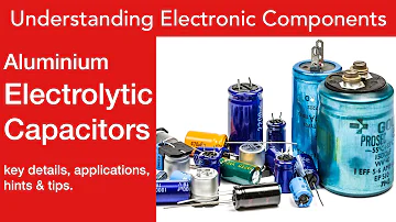
What is an Aluminium Electrolytic Capacitor | Basics / Tutorial
Catalog
| I. Structure | |
| II. Advantages and Disadvantages | |
| III. Development |
I. Structure
The core of an aluminum electrolytic capacitor is made up of four layers of overlapped and wound anode aluminum foil, electrolytic paper, cathode aluminum foil, and electrolytic paper; after the core is impregnated with electrolyte, it is sealed with an aluminum shell and a plastic cover to form an electrolytic capacitor. Compared with other types of capacitors, aluminum electrolytic capacitors exhibit the following obvious characteristics in structure:

1. The working medium of aluminum electrolytic capacitors is to generate a very thin layer of aluminum oxide (Al2O3) on the surface of the aluminum foil by anodizing. This oxide dielectric layer and the anode of the capacitor are combined to form a complete system. Interdependence, cannot be independent of each other; what we usually call a capacitor, its electrodes and dielectric are independent of each other.
2. The anode of an aluminum electrolytic capacitor is an aluminum foil with an Al2O3 dielectric layer formed on the surface. The cathode is not the negative foil we are used to thinking, but the electrolyte of the capacitor.
3. The negative foil acts as an electrical lead-out in the electrolytic capacitor, because the electrolyte as the cathode of the electrolytic capacitor cannot be directly connected to the external circuit, and an electrical path must be formed through another metal electrode and other parts of the circuit.
4. The anode aluminum foil and cathode aluminum foil of aluminum electrolytic capacitors are usually corroded aluminum foil, and the actual surface area is much larger than its apparent surface area. This is one reason why aluminum electrolytic capacitors usually have a large capacitance. Due to the use of aluminum foil with many fine etched holes, the liquid electrolyte is usually needed to more effectively use its actual electrode area.
5. Since the dielectric oxide film of the aluminum electrolytic capacitor is obtained by anodic oxidation, and its thickness is proportional to the voltage applied by anodic oxidation, in principle, the thickness of the dielectric layer of the aluminum electrolytic capacitor can be artificially Precise control.
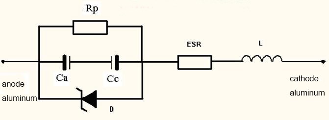
The circuit model of aluminum electrolytic capacitors
II. Advantages and Disadvantages
1. Advantages
(1) The electric capacity per unit volume is extremely large. The lower the working voltage, the more prominent the characteristics in this respect, so it is particularly suitable for miniaturization and large-capacity capacitors. For example, the specific capacity of the CD26 type low-voltage large-capacity aluminum electrolytic capacitor is about 300μF/cm3, while the specific capacity of other low-voltage chip ceramic capacitors, which is also distinctive in miniaturization, is generally not more than 2μF/cm3. .
(2) Aluminum electrolytic capacitors have "self-healing" characteristics during operation. The so-called "self-healing" feature means that the defects or defects of the dielectric oxide film can be repaired at any time during the working process of the capacitor, restore its proper insulation ability, and avoid the avalanche breakdown of the dielectric.
(3) The dielectric oxide film of aluminum electrolytic capacitors can withstand very high electric field strength. In the working process of the aluminum electrolytic capacitor, the electric field intensity of the dielectric oxide film is about 600kV/mm, which is more than 30 times that of the paper dielectric capacitor.
(4) Very high-rated electrostatic capacity can be obtained. Low-voltage aluminum electrolytic capacitors can easily obtain a capacitance of thousands or even tens of thousands of microfarads. Generally speaking, only electrolytic capacitors can be used for capacitors required for power supply filtering and AC bypass.
2. Disadvantages
(1) The insulation performance is poor. It can be said that aluminum electrolytic capacitors have the worst insulation performance among all types of capacitors. For aluminum electrolytic capacitors, leakage current is usually used to characterize their insulation performance. The leakage current of high-voltage large-capacity aluminum electrolytic capacitors can reach below 1mA.
(2) The loss factor is relatively large, and the DF of low-voltage aluminum electrolytic capacitors is usually above 10%.
(3) Aluminum electrolytic capacitors have poor temperature characteristics and frequency characteristics.
(4) Aluminum electrolytic capacitors have polarity. When used in electronic circuits, the anode of the aluminum electrolytic capacitor should be connected to the point of high potential in the circuit, and the cathode should be connected to the point of low potential in order to function normally. If the connection is reversed, the leakage current of the capacitor will increase sharply, and the core will heat up seriously, causing the capacitor to fail, and it may burn and explode, and damage other devices on the circuit board.
(5) The working voltage has a certain upper limit. According to the special production method of the dielectric oxide film of aluminum electrolytic capacitors, the maximum working voltage is generally 500V, and the development potential is very limited; for other non-chemical capacitors, as long as the thickness of the dielectric is appropriately thickened, the theoretical working voltage can be Reach any upper limit.
(6) The performance of aluminum electrolytic capacitors is easily degraded. When using aluminum electrolytic capacitors that have been stored for a long time, it is not advisable to apply the rated working voltage suddenly, but gradually increase the voltage to the rated voltage.
(7) Because traditional aluminum electrolytic capacitors use electrolytes as the cathode, there are big obstacles in chip-type, so the chip-type process lags behind ceramic capacitors and metalized film capacitors.
III. Development
In terms of current output, aluminum electrolytic capacitors occupy a second place among capacitors. This type of capacitor was originally a general DC capacitor, but now it has developed from DC to AC, from low temperature to high temperature, from low voltage to high voltage, from general type to special type, from general structure to chip type, flat type, etc. structure. The upper limit capacity has been extended to about 0.1F, the operating frequency has reached 30kHz, the operating temperature range has reached -55℃-125℃, and some even reached 150℃, and the rated voltage has reached 700V. In short, the development of aluminum electrolytic capacitors is becoming wider and wider. The features that led to these developments are as follows:
1. In terms of materials, the aluminum foil used today is very sophisticated in composition and structure. High purity is no longer required. For example, for anode foils, the purity is required to be high enough. In order to improve the number of initial corrosion points, the mechanical strength, and the performance of the dielectric oxide film, the foil must contain certain impurities. And some use alloy foil. In terms of structure, for low-voltage foils, the cubic structure is not required to account for a large proportion, but for high-voltage foils, this structure is required to account for more than 80% to 90%. On the cathode foil. In order to increase its specific volume, an alloy aluminum foil with a certain impurity content with random orientation of crystal grains is required. The working electrolyte consists of three components. That is solvents, solutes, and additives, such as electrolytes that have been used for a long time, whose components are ethylene glycol, glycerin, boric acid, and ammonia. Due to the development of aluminum electrolytic capacitors, this electrolyte is far from being able to meet the requirements, so many new electrolytes have been produced to reduce the operating temperature range of capacitors (such as -55°C-125°C). The formula principles of these new electrolytes are ① Mix two solvents. To achieve complementarity. ②Two kinds of weak acids are used to provide the required two kinds of anion groups. ③Add alkali, such as organic amine, to adjust the pH value and flash voltage of the electrolyte. Change its resistivity. ④ Additives to improve the electrolyte characteristics, such as phosphoric acid or its salt to prevent the hydration of the aluminum oxide film, dinitrobenzene to absorb hydrogen, etc., and ethylene oxide to increase the flash voltage of the electrolyte.
2. In terms of technology, in addition to the realization of mechanization and automation of production, the progress in the process of aluminum electrolytic capacitors is mainly two processes of corrosive phase empowerment. The corrosion coefficient of aluminum foil is not only very high (low-voltage capacitor foil has reached 100, and high-voltage capacitors have reached 30), and aluminum foil with different pit shapes can be corroded according to the performance requirements of capacitors. The corrosion process is a dynamic balance process of the type, concentration, temperature, original foil composition, structure, surface state, foil speed during the corrosion process, and power source type, waveform, frequency, voltage, etc. The problem is how to get the best dynamic balance and how to determine the best pass balance according to the requirements. Therefore, it cannot be said that the current corrosion process has reached the best state. The current energizing process can produce high-quality dielectric oxide films, and according to different requirements, different dielectric oxide films can be produced. For example, for DC capacitors, γ and γ'-type crystalline aluminum oxide films can be produced. AC capacitors are amorphous films. The biggest progress of the energizing process is the ability to transform the aluminum hydroxide film into a dielectric aluminum oxide film and form a waterproof layer on its surface. In addition, defects and cracks in the dielectric film can be eliminated.
3. In terms of structure, the structure of aluminum electrolytic capacitors has been diversified, in addition to the above-mentioned liquid aluminum electrolytic capacitors. There are also solid aluminum electrolytic capacitors. There are two main structural forms, one is the foil-wound shape, and the other is sintered porous block of aluminum powder. The solid electrolyte used is mainly MnO2. The structure of aluminum electrolytic capacitors has been diversified, such as double anode structure, counter-cathode structure, book type structure, triangle structure, and chip structure. Among them, the appearance of chip aluminum electrolytic capacitors is another advancement of aluminum electrolytic capacitors. Because if there is no aluminum foil with high specific volume, high-temperature resistant electrolyte, excellent sealing structure, and fine processing technology, it is difficult to make a chip aluminum electrolytic capacitor that meets the requirements. The purpose, the chip rate is still in comparison.
 UTMEL
UTMEL
We are the professional distributor of electronic components, providing a large variety of products to save you a lot of time, effort, and cost with our efficient self-customized service. careful order preparation fast delivery service
What are aluminum electrolytic capacitors used for?
Aluminum electrolytic capacitors (electrolytics) are widely used in power supply applications requiring high capacitance in energy-dense, small-volume packages having very low equivalent series resistance (ESR).
How long do aluminum electrolytic capacitors last?
Aluminum electrolytic capacitor is the shortest life parts in power supplies. Other parts, like resin, have also their life, but they are 20 - 30 or over years.
How do you read an electrolytic aluminum capacitor?
The value of the capacitor is denoted in picofarads for ceramic, film, and tantalum capacitors, but for aluminium electrolytic capacitors the value is denoted in microfarads. For small values the letter R is used to denote a decimal point, e.g. 0R5 is 0.5, 1R0 is 1.0 and 2R2 is 2.2, etc.
 AI Server MLCCs: Why NVIDIA Rubin Racks Require Over 600,000 CapacitorsUTMEL02 June 20261758
Next-generation AI servers like NVIDIA's Rubin architecture require over 600,000 MLCCs per rack due to extreme power densities exceeding 120kW. This transition from GB300 demands high-capacitance, low-ESR capacitors with X7R/X7S dielectrics to handle intense transient responses and thermal loads, forcing procurement teams to navigate extended 24-week lead times for these specialized components.
Read More What is Feedthrough Capacitor?UTMEL06 November 202141090
Hello, everyone. I am Rose. Today I will introduce the feedthrough capacitor to you. The feedthrough capacitor is a three-terminal capacitor that is used to reduce high frequencies. The feedthrough capacitor, unlike regular three-terminal capacitors, is directly installed on the metal panel, resulting in a lower grounding inductance and a negligible effect on the lead inductance.
Read More Detailed Explanation About Twenty Kinds of CapacitorUTMEL08 November 20219162
Hello everyone, I am Rose. Today I will introduce 20 kinds of capacitor to you. I will illustrate them in three or four aspects: Structure, features, Usages, advantages and disadvantages.
Read More What is a Polypropylene Capacitor?UTMEL08 November 202121517
A polypropylene capacitor is a kind of capacitor with a very stable electric capacity. It is often used in applications requiring very precise capacitance and can replace most polyphenylene or mica capacitors.
Read More What is the Difference between MOM, MIM and MOS Capacitors?UTMEL17 April 202569694
This article mainly introduces the structure, principle, advantages and disadvantages of MOM, MIM and MOS capacitors and the difference between them.
Read More
Subscribe to Utmel !
![FBP-PIC18-Q40-Q41-ISO26262]() FBP-PIC18-Q40-Q41-ISO26262
FBP-PIC18-Q40-Q41-ISO26262Microchip Technology
![MIKROE-4943]() MIKROE-4943
MIKROE-4943MikroElektronika
![MIKROE-4987]() MIKROE-4987
MIKROE-4987MikroElektronika
![MIKROE-4942]() MIKROE-4942
MIKROE-4942MikroElektronika
![MIKROE-5065]() MIKROE-5065
MIKROE-5065MikroElektronika
![MIKROE-4965]() MIKROE-4965
MIKROE-4965MikroElektronika
![MIKROE-5053]() MIKROE-5053
MIKROE-5053MikroElektronika
![MIKROE-4876]() MIKROE-4876
MIKROE-4876MikroElektronika
![MIKROE-4933]() MIKROE-4933
MIKROE-4933MikroElektronika
![MIKROE-4824]() MIKROE-4824
MIKROE-4824MikroElektronika
