
 Product
 Brand
Brand Articles
 Tools
Tools
Circuit Breaker: Working Principle, Types and Structure

What is a Circuit Breaker
Catalog
| |
| |
I Working Principle
A circuit breaker is an automatically operated electrical switch designed to protect an electrical circuit from damage caused by excess current from an overload or short circuit. It is generally composed of a contact system, an arc extinguishing system, an operating mechanism, a trip unit, and housing.
When a short circuit occurs, the magnetic field generated by a large current (generally 10 to 12 times the rated current) overcomes the reaction spring, the trip unit activates the operating mechanism, and the switch trips instantaneously. When the circuit is overloaded, the current increases, heat generation intensifies, and the bimetallic strip deforms to a certain degree, pushing the mechanism to operate (the greater the current, the shorter the operating time).
High-voltage circuit breakers are designed to interrupt fault currents at voltage levels above 1000V. These breakers must extinguish arcs of 1500V and currents ranging from 1500-2000A or higher. These arcs can extend up to 2 meters and continue burning without proper extinguishing mechanisms. Therefore, arc extinction is a critical challenge for high-voltage circuit breakers.

Figure 1. Arc Extinction
The principle of arc blowing and arc extinguishing primarily involves cooling the arc to reduce thermal dissipation. Additionally, lengthening the arc strengthens the recombination and diffusion of charged particles. Simultaneously, charged particles in the arc gap are blown away, and the dielectric strength of the medium is quickly restored. Modern circuit breakers employ various arc-extinguishing media including air, vacuum, SF6 gas, and oil.
Low-voltage circuit breakers, also called automatic air switches or miniature circuit breakers (MCBs), operate at voltage levels below 1000V. They can be used to connect and disconnect load circuits and control motors that start infrequently. Their function is equivalent to the combined capabilities of electrical systems such as knife switches, overcurrent relays, undervoltage relays, thermal relays, and leakage protectors, making them essential protection devices in low-voltage distribution networks.
Low-voltage circuit breakers offer multiple protection functions (overload, short circuit, undervoltage protection, etc.) with adjustable operating values, high breaking capacity, and safe, convenient operation, which explains their widespread use in residential, commercial, and industrial applications.
Low-voltage circuit breakers consist of an operating mechanism, contacts, protection devices (various trip units), and arc-extinguishing systems. The main contacts can be operated manually or electrically. After the main contacts close, the free-tripping device locks them in the closed position.
The coil of the overcurrent trip unit and the thermal element of the thermal trip unit are connected in series with the main circuit, while the coil of the undervoltage trip unit is connected in parallel with the power supply.
When the circuit experiences a short circuit or severe overload, the armature of the overcurrent tripping device pulls in, causing the free-tripping device to operate, and the main contacts disconnect the main circuit. When the circuit is overloaded, the thermal element of the thermal trip unit heats up and bends the bimetallic strip, pushing the free-tripping mechanism to move. When the circuit experiences undervoltage, the armature of the undervoltage trip unit releases, activating the free trip mechanism.
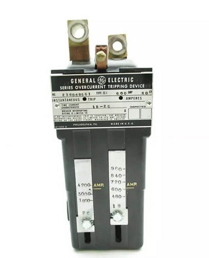
Figure 2. Over-current Tripping Device
The shunt trip unit is used for remote control. During normal operation, the coil is de-energized. When distance control is required, pressing the start button energizes the coil, causing the circuit breaker to trip.
II Working Conditions
Circuit breakers must operate within specified environmental conditions to ensure reliable performance and longevity. The following are standard operating conditions based on IEC and IEEE standards:
1. Ambient Temperature
Upper limit: +40°C (104°F)
Lower limit: -5°C (23°F) for indoor installations; -25°C (-13°F) for outdoor installations
Average value within 24h: < +35°C (95°F)
2. Altitude
The altitude of the installation site should not exceed 2000m (6562 feet) above sea level. For installations above this altitude, derating factors must be applied due to reduced air density affecting cooling and dielectric strength. Special high-altitude circuit breakers are available for installations up to 4000m.
3. Atmospheric Conditions
The relative humidity of the atmosphere should not exceed 50% when the ambient air temperature is +40°C. Higher relative humidity is acceptable at lower temperatures. The monthly average maximum relative humidity of the wettest month is 90%, with an average monthly minimum temperature of +25°C for that month. Condensation that occurs on the product surface due to temperature changes must be considered in the installation design.
4. Pollution Level: Pollution degree 3 (as per IEC 60664-1), indicating normal indoor environments or outdoor environments with moderate pollution.
5. Control Circuit Requirements
(1) The integrity of the protection device and the tripping and closing circuits in the control circuit must be continuously monitored to ensure normal operation of the circuit breaker. Modern digital circuit breakers include self-diagnostic features for this purpose.
(2) The position status of normal closing and opening of the circuit breaker should be clearly indicated, with distinct indicator signals during automatic closing and automatic tripping operations.
(3) After closing and tripping operations are completed, the command pulse should be terminated to cut off the power supply to the closing or tripping mechanism, preventing unnecessary energy consumption and potential damage.
(4) When there is no mechanical anti-pumping device, an electrical anti-pumping device should be installed to prevent rapid open-close cycling that could damage the breaker.

Figure 3. Electrical Anti-pumping Device
(5) The fault tripping signal circuit of the circuit breaker should be wired according to the "non-correspondence principle" to ensure fail-safe operation.
(6) For equipment that may experience abnormal working conditions or malfunctions, a warning signal should be installed to alert operators before critical failures occur.
(7) The power supply for spring-operated and manual operating mechanisms can be DC or AC. However, electromagnetic operating mechanisms should use DC power supply for more reliable operation. Common control voltages include 24V DC, 48V DC, 110V DC, 125V DC, and 220V AC.
III Circuit Breaker Properties
The key characteristics and ratings of circuit breakers include:
1. Rated Operational Voltage (Ue)
The voltage at which the circuit breaker is designed to operate under normal (non-fault) conditions. Common ratings include 120V, 240V, 480V, 600V for low-voltage applications, and 15kV, 27kV, 38kV for medium-voltage applications.
2. Rated Current (In)
The maximum continuous current value that a circuit breaker equipped with a specific overcurrent trip relay can withstand at the ambient temperature specified by the manufacturer without exceeding the temperature limits of current-carrying components. This rating ensures the breaker can carry normal load currents indefinitely without tripping.
3. Short-circuit Relay Tripping Current (Im)
The short-circuit tripping relay (instantaneous or short-time delayed) rapidly trips the circuit breaker when high fault current appears. The trip limit is the setting value Im, typically adjustable between 5 to 15 times the rated current depending on the application and breaker type.
4. Rated Short-circuit Breaking Capacity (Icu or Icn)
The rated short-circuit breaking current is the highest (prospective) current value that the circuit breaker can interrupt without being damaged. This value represents the root-mean-square (RMS) value of the AC component of the fault current, with the DC transient component assumed to be zero for standardization purposes. For industrial circuit breakers, this is designated as Icu, while for residential/household circuit breakers, it's designated as Icn. Values are typically expressed in kA RMS, with common ratings of 6kA, 10kA, 15kA, 25kA, 35kA, 50kA, and higher for specialized applications.
5. Service Short-circuit Breaking Capacity (Ics)
The rated breaking capacity of circuit breakers is divided into two categories: rated ultimate short-circuit breaking capacity (Icu) and rated service short-circuit breaking capacity (Ics).
All circuit breakers have both Icu and Ics as important technical indicators. For circuit breakers used on branch lines, meeting the Icu requirement is typically sufficient. However, for circuit breakers used on main lines or critical distribution points, both Icu and Ics requirements must be satisfied. The Ics is typically 25%, 50%, 75%, or 100% of Icu, depending on the breaker class. Relying solely on Icu for breaking capacity assessment can create safety hazards, as the breaker may not be suitable for repeated fault interruptions.
While some may prefer selecting breakers with higher ratings, excessively high ratings result in unnecessary costs. For example, for the same type of circuit breaker, an H-type (high breaking capacity) can cost 1.3 to 1.8 times more than an S-type (standard breaking capacity). Therefore, it's important to select appropriate ratings based on actual system requirements rather than blindly pursuing the highest specifications.
IV Circuit Breaker Types
Circuit breakers can be classified according to various criteria including usage, structural form, operation method, number of poles, installation method, arc-extinguishing medium, and application. The following table summarizes the main classification categories:
Classification Criteria | Types |
Usage Category | Non-selective type (Type A) & Selective type (Type B) |
Structure | Air circuit breaker (ACB), molded case circuit breaker (MCCB), miniature circuit breaker (MCB) |
Operation Mode | Manual operation, motor-operated, spring-operated, pneumatic, hydraulic |
Number of Poles | Single-pole (1P), two-pole (2P), three-pole (3P), and four-pole (4P) |
Installation Method | Fixed type, plug-in type, drawer type, and DIN rail mounted |
Arc Extinguishing Medium | Air, vacuum, SF6 gas, oil (mineral oil or synthetic ester) |
Arc-extinguishing Technology | Standard arc-extinguishing and current-limiting type |
Application | Power distribution, motor protection, residential/household, residual current (earth leakage) protection, DC applications, photovoltaic systems, and specialized industrial uses |
V Circuit Breaker Structure
1. Internal Accessories
(1) Auxiliary Contacts
Auxiliary contacts are mechanically linked to the main circuit's opening and closing mechanism, primarily used to indicate the opening and closing status of the circuit breaker. They connect to the control circuit to control or interlock related electrical devices through the circuit breaker's operation, such as outputting signals to indicator lights, relays, or programmable logic controllers (PLCs).
For molded case circuit breakers (MCCBs) with a rated frame current (Inm) of 100A, they typically have a single changeover contact. Those rated 225A and above feature a bridge contact structure with a conventional thermal current rating of 3A. MCCBs rated 400A and above can be equipped with two normally open and two normally closed contacts, with a conventional thermal current rating of 6A. The operational life of auxiliary contacts matches the total operational life of the circuit breaker.
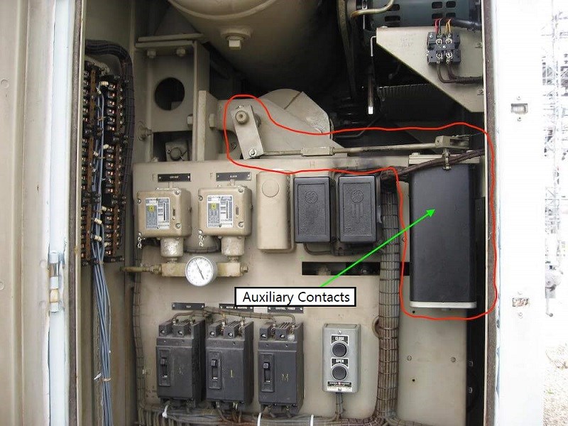
Figure 4. A Bank of Auxiliary Contacts in Oil Circuit Breaker
(2) Alarm Contacts
Alarm contacts are primarily used to signal circuit breaker faults, activating only when the circuit breaker trips due to a fault condition. When overload, short circuit, or undervoltage faults occur in the circuit breaker's load, the breaker trips freely, and the alarm contact moves from its normally open position to closed, activating indicators, electric bells, buzzers, or SCADA systems in the auxiliary circuit to display the fault trip status.
Since circuit breaker fault tripping due to load failures is relatively infrequent, the operational life of alarm contacts is typically 1/10 of the circuit breaker's total operational life. The working current of alarm contacts generally does not exceed 1A.
(3) Shunt Trip
A shunt trip is a tripping device excited by a voltage source independent of the main circuit voltage. It is an accessory for remote control opening operations. When the supply voltage is between 70%-110% of the rated control power supply voltage, the circuit breaker can be reliably tripped.
The shunt trip operates on a short-time duty cycle, and the coil energization time should generally not exceed 1 second to prevent coil burnout. To protect against coil damage, a microswitch is connected in series with the shunt trip coil. When the shunt trip armature is pulled in, the microswitch changes from normally closed to normally open.
Since the power and control circuit of the shunt trip is interrupted, even if the button is manually pressed continuously, the shunt coil will not be re-energized, preventing coil burnout. When the circuit breaker is closed again, the microswitch returns to its normally closed position.
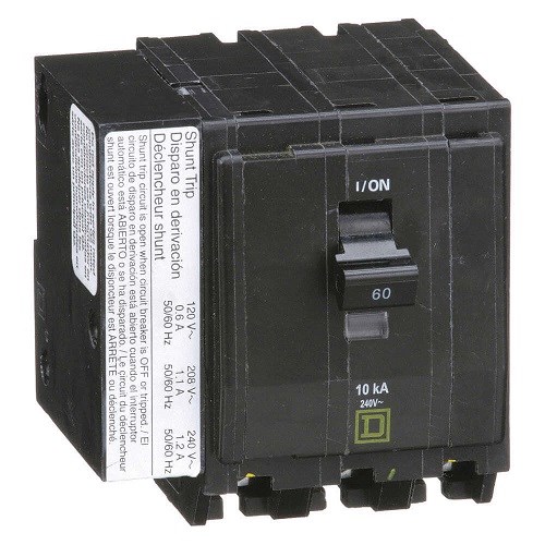
Figure 5. Shunt Trip Circuit Breaker
(4) Undervoltage Trip
An undervoltage trip is a device that causes the circuit breaker to open with or without delay when its terminal voltage drops to a specified range. It operates when the supply voltage drops (even gradually) to between 35% and 70% of the rated operating voltage.
When the supply voltage equals 35% of the rated operating voltage of the trip unit, the undervoltage trip should prevent the circuit breaker from closing. When the supply voltage equals or exceeds 85% of the rated operating voltage, it should ensure reliable circuit breaker closing under all conditions. Therefore, when a significant voltage drop occurs in the supply voltage of the protected circuit, the circuit breaker automatically disconnects, protecting load equipment downstream from undervoltage damage.
During use, the undervoltage trip coil is connected to the power supply side of the circuit breaker, and the circuit breaker can only close when the undervoltage trip is energized.
2. External Accessories
(1) Electric Operating Mechanism
This accessory enables remote automatic opening and closing of circuit breakers, including motor-operated mechanisms and electromagnet-operated mechanisms.
Motor-operated mechanisms are used for molded case circuit breakers with Inm of 400A and above, while electromagnet-operated mechanisms are suitable for MCCBs with Inm of 225A and below. Whether electromagnet or motor-driven, their pull-in and rotation directions are identical, with the internal cam position determining closing and opening operations. When operated electrically, the circuit breaker should reliably close at any voltage between 85% and 110% of the rated control voltage.
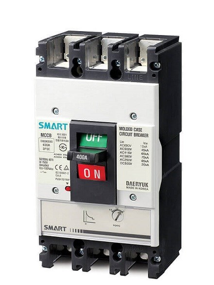
Figure 6. Molded Case Circuit Breaker
(2) Rotary Handle
Suitable for molded case circuit breakers, a rotary handle mechanism is installed on the circuit breaker cover. The rotary shaft of the handle is installed in its matching mechanism hole. The other end of the rotary shaft passes through the door hole of the enclosure, and the handle is mounted on the shaft head exposed on the door of the complete assembly, with the round or square base fixed to the door with screws.
This installation enables operators to rotate the handle clockwise or counterclockwise outside the door to close or open the circuit breaker. Simultaneously, the handle mechanism can ensure the cabinet door remains closed when the circuit breaker is closed, until the handle is opened or the breaker trips. In emergencies, when the circuit breaker is "closed" and the electrical panel needs to be opened, pressing the red release button on the side of the handle base allows door opening.
(3) Extension Handle
An external extension handle mounts directly on the circuit breaker handle. It is generally used for large-capacity circuit breakers rated 600A and above to facilitate manual opening and closing operations by providing additional mechanical leverage.
(4) Handle Locking Device
A clip is installed on the handle frame, and the handle can be secured with a padlock through a punched hole. When the circuit breaker is closed, the handle locking device prevents unauthorized personnel from disconnecting power and causing operational failures. Additionally, when the load side of the circuit breaker requires maintenance or must remain de-energized, it prevents accidental circuit breaker closure, ensuring worker safety through lockout/tagout (LOTO) procedures.
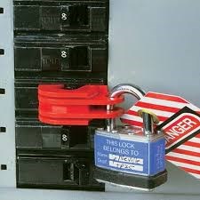
Figure 7. Circuit Breaker Locking Device
VI Wiring Methods
Circuit breakers can be wired using several methods: front-of-board wiring, rear-of-board wiring, plug-in type, and drawer type. Front-of-board wiring is the most common method for smaller installations.
1. Rear-of-Board Wiring
The primary advantage of rear-of-board wiring is that circuit breakers can be replaced or repaired without rewiring, requiring only disconnection of the upstream power supply.
Due to the specialized structure, products are equipped with dedicated mounting plates, mounting screws, and wiring screws according to design requirements. It's crucial to note that contact reliability in large-capacity circuit breakers directly affects normal operation, so installation must strictly follow manufacturer specifications. Proper torque values must be applied to all connections to ensure reliable contact and prevent overheating.
2. Plug-in Wiring
On the installation board of the complete assembly, a circuit breaker mounting base with 6 or more socket contacts is first installed. The mounting base features a connecting plate on the surface or bolts behind it, with power and load conductors pre-connected to the mounting base.
During use, the circuit breaker is directly inserted into the mount. If the circuit breaker fails, simply remove the faulty unit and replace it with a functional one. Plug-in wiring replacement time is significantly shorter than front or rear-of-board wiring, offering greater convenience and reduced downtime. This method is particularly popular in industrial control panels and motor control centers (MCCs).
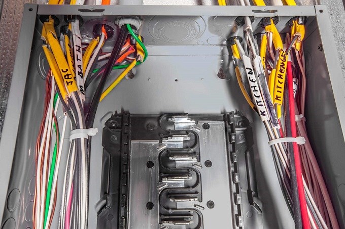
Figure 8. Wiring in Circuit Breaker
3. Drawer-type Wiring
The circuit breaker's insertion and withdrawal from the drawer are controlled by rotating a crank handle clockwise or counterclockwise. Both main circuit and secondary circuit connections use plug-in structures, eliminating the need for the isolator required in fixed-type installations. This dual-purpose design is more economical while providing significant operational and maintenance convenience, enhancing safety and reliability. Notably, the main circuit contact holder of the drawer base is often interchangeable with contact holders of fuse-switch combinations, providing additional flexibility.
Drawer-type circuit breakers typically feature three positions: connected (test), disconnected (service), and withdrawn (isolated). This design allows for safe testing and maintenance while providing clear visual indication of the breaker's status.
Additional Considerations for Modern Circuit Breakers:
Modern circuit breakers increasingly incorporate smart features including:
Digital trip units with programmable settings and LCD displays
Communication capabilities (Modbus, Profibus, Ethernet/IP) for integration with building management systems
Energy metering and power quality monitoring functions
Predictive maintenance alerts based on operational data
Arc fault detection for enhanced fire prevention
Ground fault protection with adjustable sensitivity
When selecting circuit breakers, it's essential to consider not only electrical ratings but also coordination with upstream and downstream protective devices, environmental conditions, and future expansion requirements. Proper coordination ensures selective tripping, where only the breaker closest to the fault operates, minimizing disruption to the overall system.
Related Articles:
Structure and Working Principle of Field Effect Transistors
What is an Electrical Connector?
Understanding Circuit Breaker Ratings and Selection
Last updated: November 2025
 UTMEL
UTMEL
We are the professional distributor of electronic components, providing a large variety of products to save you a lot of time, effort, and cost with our efficient self-customized service. careful order preparation fast delivery service
1.What is a circuit breaker and how does it work?
Circuit breakers act as resettable fuses . These are automatically operated electrical switches that protect electrical circuits from overloading or short circuiting. They detect faults and then stop the flow of electricity.
2.What is called circuit breaker?
A circuit breaker is an automatically operated electrical switch designed to protect an electrical circuit from damage caused by excess current from an overload or short circuit. Its basic function is to interrupt current flow after a fault is detected.
3.What happens when a circuit breaker trips?
When it is said that a circuit breaker “trips,” it means that circuit has detected what's known as a fault condition and has shut itself off to prevent the wiring from overheating and potentially igniting itself.
4.What is the purpose of a circuit breaker?
A circuit breaker is an electrical switch designed to protect an electrical circuit from damage caused by overcurrent/overload or short circuit. Its basic function is to interrupt current flow after protective relays detect a fault.
5.What are the types of circuit breaker?
There are three basic circuit breaker varieties: standard breakers (which include both single-pole and double-pole circuit breakers), ground fault circuit interrupter circuit breakers (GFCIs) and arc fault circuit interrupter circuit breakers (AFCIs).
 What Size Wire for a 60 Amp Breaker? The Complete NEC GuideUTMEL22 May 2026162
Selecting the right wire size for a 60-amp breaker requires evaluating conductor materials, insulation, and distance. While 6 AWG copper THHN or 4 AWG aluminum in conduit is standard, NM-B Romex limits 6 AWG to 55 amps, requiring 4 AWG copper. Additionally, installers must account for continuous load limits, ground wire sizing, and voltage drop over long runs.
Read More What is Surge?UTMEL09 February 20226464
Hello everyone, I am Rose. Today I will introduce surge to you. Surge is an overvoltage that occurs suddenly and surpasses the typical operating voltage. A surge is a brief wave of current, voltage, or power in a circuit, in general.
Read More: The Complete 2025 Guide") Surge Protection Devices (SPD): The Complete 2025 GuideUTMEL25 December 202527887
Surge Protection Devices (SPD): The Complete 2025 GuideUTMEL25 December 202527887A surge protection device (SPD), also called a surge protector, is an electronic device that provides safety protection for various electronic equipment, instruments, and communication lines. When a spike current or voltage is suddenly generated in the electrical circuit or communication circuit due to external interference, the surge protection device can conduct and shunt in a very short time, so as to prevent the surge from damaging other equipment in the circuit.
Read More What is a Ground Fault Circuit Interrupter?UTMEL27 March 20255333
A ground fault circuit interrupter(GFCI) is an electrical device installed to protect against severe electric shocks. It can also reduce electrocutions, minimize electrical burns and shock injuries, and detect ground faults, and interrupts the flow of electric current.
Read More What is Vacuum Circuit Breaker?UTMEL12 October 20219624
Hello, I am Rose. Welcome to the new post today. The name "vacuum circuit breaker" comes from the fact that both the arc extinguishing medium and the insulating medium of the contact gap after arc extinguishing are high vacuum; it has the advantages of compact size, light weight, frequent operation, and no arc extinguishing maintenance. This article introduces basis knowledge about vacuum circuit breaker.
Read More
Subscribe to Utmel !
![JANTX1N5539BUR-1/TR]() JANTX1N5539BUR-1/TR
JANTX1N5539BUR-1/TRMicrochip Technology
![JANTX1N4963US/TR]() JANTX1N4963US/TR
JANTX1N4963US/TRMicrochip Technology
![JAN2N3737UB/TR]() JAN2N3737UB/TR
JAN2N3737UB/TRMicrochip Technology
![JANTX1N5550US/TR]() JANTX1N5550US/TR
JANTX1N5550US/TRMicrochip Technology
![JANTX1N4985/TR]() JANTX1N4985/TR
JANTX1N4985/TRMicrochip Technology
![JANTX1N3595A-1/TR]() JANTX1N3595A-1/TR
JANTX1N3595A-1/TRMicrochip Technology
![JANTXV1N3016DUR-1/TR]() JANTXV1N3016DUR-1/TR
JANTXV1N3016DUR-1/TRMicrochip Technology
![1N748A/TR]() 1N748A/TR
1N748A/TRMicrochip Technology
![1N5622US/TR]() 1N5622US/TR
1N5622US/TRMicrochip Technology
![JANTX1N4104UR-1/TR]() JANTX1N4104UR-1/TR
JANTX1N4104UR-1/TRMicrochip Technology
