 Product
 Brand
 Articles
 Tools

Crimp Connector Failures: Strip Length, Tooling, and Pull-Test Checks
Why Crimp Terminations Fail: Short Answer & Quick Diagnostic Framework
Crimp connector failures rarely happen randomly; they trace directly to improper mechanical compression, wire-placement errors, corrosion, or localized electrothermal stress (Alter Technology). Because an under-compressed or misaligned termination can easily pass a casual visual glance or manual tug while failing later under electrical load or vibration, industry workmanship standards such as IPC/WHMA-A-620 Revision E[6] evaluate crimps through a combination of magnified visual geometry, non-destructive crimp height measurement, and mechanical pull-force testing. Preventing field failures requires controlling four linked variables on the shop floor: wire-to-terminal sizing, transition-zone strip placement, tooling alignment, and structured lot sampling.
When troubleshooting an intermittent harness or a burned terminal pin, technicians must distinguish between housing-level defects and termination-level failures. Understanding what is an electrical connector from a mechanical systems perspective clarifies why the crimp zone—where raw copper conductor strands are cold-welded into the terminal barrel—serves as both the electrical bottleneck and the primary mechanical anchor of the assembly. The diagnostic rules in this guide focus strictly on open-barrel (stamped-and-formed) and closed-barrel (machined or heavy-duty lug) wire-to-terminal crimps across industrial, automotive, and aerospace harnesses, rather than cataloging connector housing families.
Symptom-to-Root-Cause Diagnostic Table
Before adjusting stripping blades or swapping press applicators, match the observed bench or field failure mode to its physical defect and process root cause:
| Field or Bench Failure Symptom | Physical Crimp Defect | Process Root Cause | Primary Verification Check |
|---|---|---|---|
| High contact resistance, voltage drop, or discolored/melted insulation | Internal micro-voids and oxidation inside the conductor barrel | Under-crimping (crimp height too loose) or oversized terminal barrel for the wire gauge | Crimp height comparator measurement against applicator data plate |
| Wire snaps cleanly at the rear entry of the terminal under vibration | Crushed, thinned copper strands or sharp metal edge cutting into wire | Over-crimping (crimp height too tight), missing/reversed rear bellmouth, or nicked strands from stripping | Magnified visual check of rear bellmouth + crimp height check |
| Intermittent open circuit despite an intact exterior crimp | Insulation jacket trapped underneath the conductor crimp wings | Wire inserted too deep past the transition zone, or wire strip length set too short | Magnified visual inspection of the transition window |
| Terminal fails to lock into housing or shorts against adjacent contact | Excessive conductor brush protruding into mating box, or bent/twisted contact body | Strip length too long, wire placed too far forward, or misaligned applicator anvil/carrier feed | Magnified visual check of brush length, cut-off tab, and axial straightness |
The "Looks Good, Fails in Service" Paradox: Under-Crimping vs. Over-Crimping
A major misconception in low-volume harness assembly is assuming that a terminal that survives a finger-tug test is reliable. As documented in failure analyses by Alter Technology and visual defect criteria from TE Connectivity[5], mechanical compression operates inside a narrow bell curve where both extremes trigger field failures:
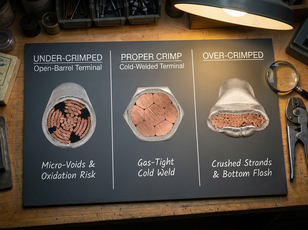
Under-Crimping (Insufficient Compression): When the crimping die does not compress the conductor barrel tightly enough, microscopic air voids remain between individual wire strands and the terminal wall. While the wire may not slide out under light hand tension, those internal voids allow moisture and oxygen ingress. Over time, strand oxidation and corrosion reduce the effective conductive contact area, spiking contact resistance and generating localized electrothermal heating under current load.
Over-Crimping (Crimp Height Too Tight): Applying excessive ram force or selecting an undersized die cavity crushes and work-hardens the copper strands. Over-compression thins the cross-sectional area of the conductor, forces sharp metal flash out the bottom seam of the terminal, and creates a brittle stress riser that fractures prematurely when exposed to engine or machinery vibration.
Wire-to-Terminal Matching: Key Specifications to Compare Before Stripping
Preventing crimp connector failure starts before a wire stripper touches the cable: both the conductor cross-sectional area (AWG or) and the wire insulation outer diameter (OD) must fall within the specified window[4] of the exact terminal part number (TE Connectivity, Molex). Matching nominal wire gauge alone is insufficient because modern wire harnesses pair identical copper gauges with vastly different insulation wall thicknesses.
Two-Zone Terminal Sizing: Conductor Barrel vs. Insulation Support Barrel
Every open-barrel terminal and insulated closed-barrel terminal contains two distinct crimping zones that must be matched independently to the wire datasheet:
Conductor Barrel Capacity: Engineered to compress a specific total cross-sectional area of copper (measured in circular mils, AWG, or) and strand configuration. Placing a small-gauge wire into an oversized conductor barrel prevents the folding wings from achieving gas-tight cold-weld compression. Conversely, forcing an oversized conductor into a small barrel leaves loose strands outside the crimp wings or over-packs the die cavity.
Insulation Support Barrel Capacity: Engineered to wrap around a specific wire insulation outer diameter (OD) to provide mechanical strain relief.
If the insulation jacket is too thick (for example, pairing heavy-wall industrial PVC wire with a terminal designed for thin-wall automotive cross-linked polyethylene): The insulation cannot seat flat in the support barrel. Either the operator fails to push the conductor all the way into the wire barrel, or the insulation crimp wings slice through the jacket and pinch the underlying copper strands.
If the insulation jacket is too thin: The insulation crimp wings close without gripping the jacket. With zero mechanical strain relief, every cable flex and vibration load transfers directly to the fragile bare copper strands at the rear of the conductor barrel.
When selecting terminal hardware for field repairs or new harness layouts, reviewing a practical breakdown of how to choose the right spade connector for any project illustrates how barrel dimensions, stud clearances, and wire gauge ratings must align with the electrical load and environmental exposure.
Common Sourcing Mistakes: The Cross-Brand Tooling & Terminal Trap
One of the most frequent root causes of recurring crimp failures on the production floor is mixing terminals from one manufacturer (or unverified substitute lots) with hand tools or press applicators built for another brand. Even when two terminals share the exact same nominal AWG range and mating pin geometry, subtle differences in brass or phosphor-bronze strip thickness, plating hardness, and wing length alter how the metal forms inside the die.
Manufacturer documentation explicitly warns against cross-brand pairing. For example, in the Molex Quality Crimping Handbook[1], tooling specifications state: "CAUTION: Molex crimp specifications are valid only when used with Molex terminals and tooling." A dedicated terminal specification sheet (such as Molex Order No. 63811-6000 for 18–22 AWG MX150 terminals) defines a strict insulation diameter window () alongside a narrow strip length range () calibrated specifically for that die profile. Always verify the active terminal reel part number against the manufacturer's current Application Specification sheet to confirm that your wire style and applicator die revision are approved together.
Strip Length and Wire Placement: Controlling Insulation Position and Conductor Brush
Wire strip length must match the terminal barrel geometry, and strip length determines the conductor brush length only when the wire insulation position is properly centered in the transition zone prior to crimping (Molex, TE Connectivity). Because crimp attributes interact dynamically during termination, an incorrect conductor brush reading can be caused by either an improper wire-stripper setting or an off-center wire insertion depth.
Anatomy of the Three Termination Placement Zones
When inspecting wire placement prior to and immediately after tool closure, technicians evaluate three adjacent zones along the terminal axis:
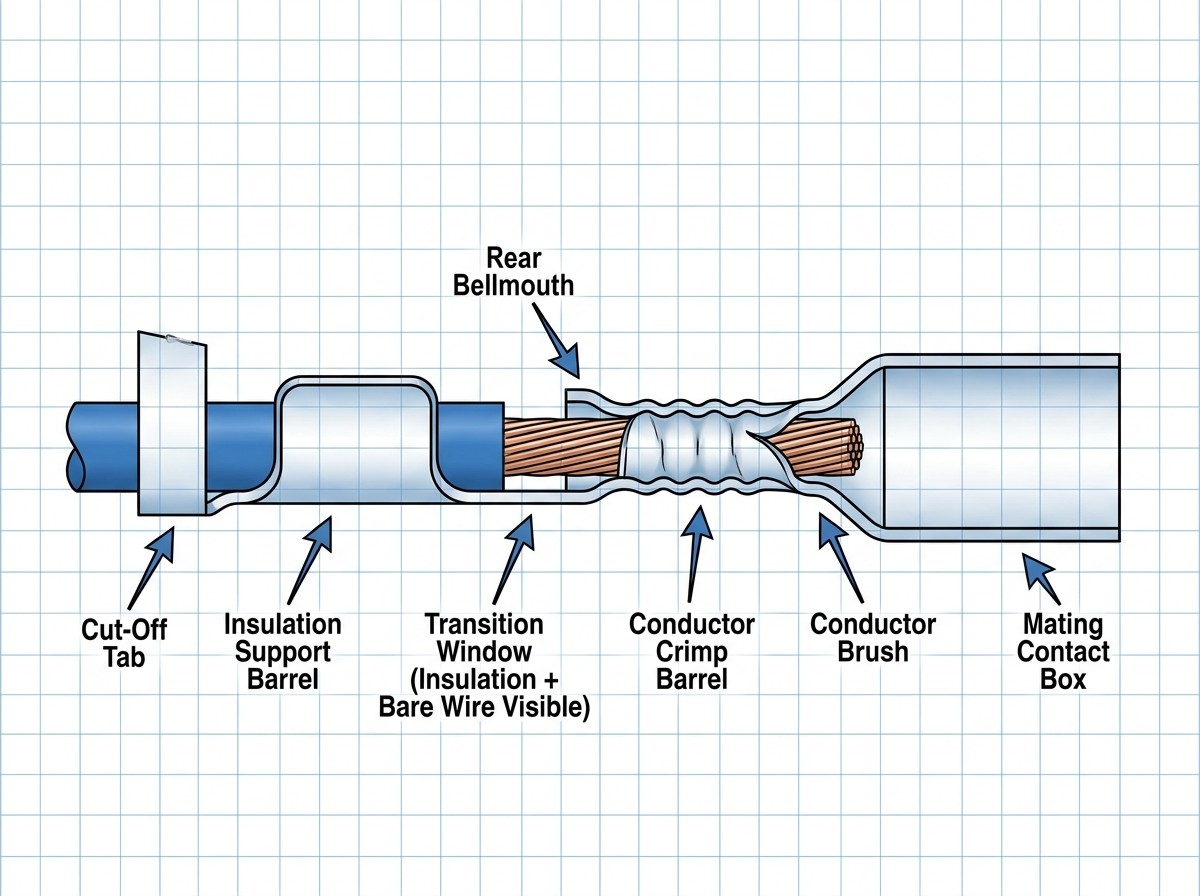
Zone 1: Insulation Grip & Transition Zone: The wire insulation jacket must be captured securely by the rear insulation barrel and end cleanly inside the transition window—the open space between the insulation crimp barrel and the conductor crimp barrel. In a properly positioned open-barrel crimp, both the cut edge of the insulation jacket and bare copper strands are clearly visible inside this transition window[2] (Molex).
Zone 2: Conductor Crimp Barrel: The wire barrel must contain 100% clean, un-nicked bare conductor strands spanning its entire effective crimp length. If the stripper blades nick, scrape, or sever even a few outer strands, tensile strength drops and electrical current crowds into the remaining intact strands. Zero insulation material may enter this barrel (TE Connectivity).
Zone 3: Conductor Brush: The exposed tips of the copper strands extending just beyond the front face of the conductor crimp barrel form the conductor brush. A visible brush proves the wire reached the front of the barrel during compression. However, the brush must never protrude forward into the mating contact box, interfere with terminal locking lances, or flare upward[3] above the top plane of the conductor crimp (TE Connectivity, Molex).
Troubleshooting Decision Tree: Strip Length Error vs. Insertion Depth Error
On the shop floor, operators frequently make the mistake of adjusting the wire-stripping machine the moment they see a missing or excessive conductor brush. As Molex emphasizes, crimp features are interdependent: changing a mechanical track or wire stop alters multiple visual attributes simultaneously. Follow this three-step decision sequence before changing stripper blade settings:
Step 1: Inspect the Transition Window Between the Insulation and Conductor Barrels
Check whether the cut edge of the wire insulation is centered halfway between the front of the insulation grip and the rear of the conductor barrel.
YES (The insulation edge is properly centered in the transition window): The operator or press wire stop positioned the wire at the correct depth. Proceed to Step 2.
NO (The insulation edge is shifted forward into the conductor barrel or pulled far back into the insulation barrel): The failure is a wire placement / insertion depth error, not a stripping error. Proceed to Step 3.
Step 2: Diagnose and Correct a Strip Length Error (Adjust the Wire Stripper)
Because the insulation is centered in the transition zone, any defect at the conductor brush is a direct result of exposed copper length:
Condition A — Conductor brush is recessed inside the conductor barrel: The wire strip length is too short. Increase the strip length setting on the stripping tool to match the terminal datasheet specification.
Condition B — Conductor brush protrudes into the mating contact area or locking mechanism: The wire strip length is too long. Decrease the strip length setting on the stripping tool.
Step 3: Diagnose and Correct a Wire Placement Error (Do Not Touch the Wire Stripper)
Measure the stripped wire against a calibrated ruler first; if the strip length matches the terminal datasheet, correct the placement mechanics:
Condition A — Insulation is trapped inside the conductor crimp barrel AND conductor brush is excessive: The wire was inserted too deep prior to tool closure. Adjust the automated press wire stop rearward, or check the hand-tool terminal locator stop.
Condition B — Insulation terminates far back inside the insulation barrel (or bare copper shows behind the terminal) AND conductor brush is missing: The wire was inserted too shallow, or the operator allowed the wire to slip backward as the hand-tool jaws closed. Train operators to seat the terminal in the locator first, bottom the wire against the stop, and maintain light forward pressure until the ratchet completes its stroke.
Crimping Tooling and Compression Geometry: Bellmouth, Anvil Impressions, and Crimp Height
Even perfectly stripped and positioned wire will fail in service if the crimping tool applies asymmetric or out-of-tolerance compression. Technicians verify tooling health by inspecting physical footprints stamped into the terminal—specifically the rear bellmouth, carrier cut-off tab, and bottom anvil impression (Molex, TE Connectivity)—and by measuring finished crimp height with a comparator against the tool's specification sheet (FS Cables).
Reading Physical Tooling Clues on the Crimped Terminal
A crimped terminal acts as a physical casting of the upper crimper and lower anvil dies. Inspecting the exterior of the barrel under magnification reveals die wear and feed misalignment immediately:
Anvil Impression: Turn the terminal over and inspect the bottom flat of the conductor barrel. The lower anvil tooling leaves a distinct depression or witness mark on the underside of the crimp (Molex). If this impression is shifted toward one side or missing on one end, the upper crimper and lower anvil are out of alignment.
Bellmouth (Funnel Flare): As the upper tooling forms the conductor barrel, it creates a flared radius—known as the bellmouth—at the rear edge of the conductor barrel where the wire enters. The bellmouth acts as a smooth funnel so the rear metal edge of the barrel cannot slice into the copper strands during cable flexing. In TE Connectivity's Crimp Quality Guidelines, two severe tooling defects are highlighted: a missing bellmouth (which shears strands) and a bellmouth formed on the wrong end (where carrier feed misalignment places the flare on the front brush edge while leaving a sharp, biting step on the rear wire-entry edge). Note that adjusting the terminal feed track to correct the bellmouth also shifts the cut-off tab length and insulation wire position (Molex).
Cut-Off Tab & Terminal Bend or Twist: Reeled terminals are sheared from a metal carrier strip during the press stroke. If the shear blade is worn or the feed finger is misadjusted, an elongated cut-off tab or sharp metal burr remains on the terminal end (Molex). Excessive cut-off tabs can puncture silicone weather seals or prevent the contact from seating in the connector housing. Similarly, incorrect stripping force or misaligned tooling guides cause vertical bend (upward or downward banana curvature) or axial twist between the crimp barrel and the mating contact box (TE Connectivity).
Non-Destructive Crimp Height Verification
Because internal voiding cannot be seen from the outside, crimp height is the primary non-destructive metric used to verify that the die compressed the conductor barrel to the exact cross-sectional area engineered by the manufacturer. Verifying that crimp height falls within the specified range is addressed in Chapter 19 of the IPC/WHMA-A-620 standard (SuperEngineer).
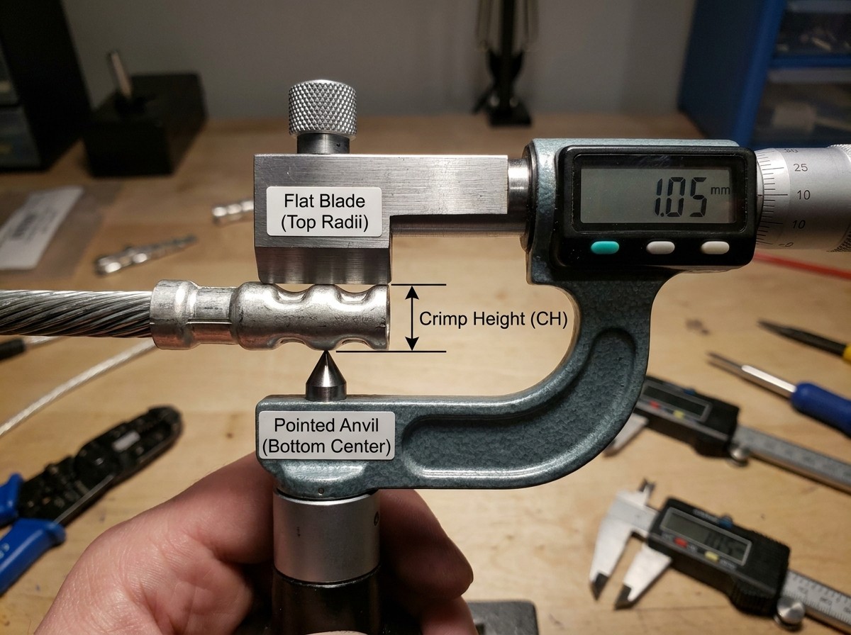
Standard flat-anvil machinist calipers cannot measure crimp height accurately because their wide jaws bridge across the terminal's raised insulation barrel or solder tail. Instead, technicians use a crimp height comparator (a specialized micrometer featuring a pointed conical anvil and a thin flat blade) (FS Cables). The flat blade rests across the top dual radii of the conductor crimp while the point centers on the bottom anvil impression at the middle of the conductor barrel. Target crimp height values and tolerances are printed directly on the hand-tool instruction sheet, the applicator data plate, or the terminal application specification sheet (FS Cables, Molex).
Magnified Visual Inspection Checklist: Catching Open- and Closed-Barrel Defects
Naked-eye inspection is insufficient for modern miniature and high-reliability wire harnesses; frontline quality screening requires inspecting terminations under a magnifying glass or low-power inspection microscope against standardized geometric acceptance criteria (Molex, TE Connectivity). Visual screening eliminates placement and feed defects before samples undergo mechanical verification.
Benchtop Visual Inspection Pass / Fail Table
Use the following five-point inspection grid during first-article setup and in-process visual checks:
| Inspection Feature | Acceptable (Pass) Criteria | Rejectable (Fail) Defect | Immediate Corrective Action |
|---|---|---|---|
| 1. Conductor Brush | Bare copper strands are visible extending slightly past the front face of the conductor barrel without exceeding top crimp height. | Strands are recessed inside the barrel, flare upward above the barrel, or protrude into the mating contact box / locking lance area. | Check transition-zone centering first; adjust wire stop if off-center, or adjust stripper length if centered. |
| 2. Insulation Position (Transition Window) | Cut edge of insulation is centered in the window between the insulation grip and conductor barrel; both bare wire and jacket are visible. | Insulation extends forward under the conductor crimp wings, or is stripped so far back that bare wire is exposed behind the terminal. | Reset press wire-stop depth or train operator on hand-tool locator seating. |
| 3. Insulation Support Crimp | Insulation wings wrap smoothly and firmly around the wire jacket to provide mechanical strain relief. | Wings pierce or slice through the insulation jacket into copper strands, or remain too loose to hold the jacket. | Adjust the independent insulation crimp height dial on the applicator, or verify wire OD against terminal spec. |
| 4. Bellmouth & Cut-Off Tab | Distinct flared bellmouth on the rear (wire-entry) edge of the conductor barrel; clean carrier cut-off tab within specification. | Bellmouth is missing, reversed onto the front edge of the barrel, or carrier cut-off tab shows excessive length or jagged burrs. | Adjust terminal feed finger / track alignment; inspect and replace worn shear blades. |
| 5. Barrel Symmetry, Anvil Mark & Straightness | Symmetrical wing roll/indent, centered anvil impression on the bottom flat, all strands captured, and straight terminal body. | Asymmetric wing roll, cracked barrel seam, stray strands outside barrel, off-center anvil mark, or vertical/axial terminal bend/twist. | Realign upper crimper and lower anvil tooling; verify wire gauge matches terminal barrel capacity. |
Why "Hand-Tug" Checks and Generic Spec Charts Fail
When training assembly technicians or auditing contract harness suppliers, beware of two persistent myths that cause high field-return rates:
The "Hand-Tug & Naked-Eye" Myth: A crimp where 30% of the copper strands were nicked during stripping, or where PVC insulation is pinched inside the rear half of the conductor barrel, will easily hold together when an operator tugs the wire by hand. The defect remains invisible until thermal cycling softens the trapped PVC jacket or continuous vibration fatigues the remaining strands.
The "One-Size-Fits-All" Tolerance Trap: Many generic online summaries quote a single fixed millimeter tolerance for crimp height, a single fraction of an inch for brush length, or a fixed percentage for insulation wrap as if those numbers apply universally. In reality, a sub-miniature 28 AWG board-to-wire contact and a heavy-duty industrial lug operate on completely different geometric scales. Never rely on memorized rules of thumb; always pull the exact dimensional tolerances from the terminal manufacturer's part-specific application specification.
Mechanical Verification and Sampling Workflow: Crimp Height vs. Pull-Force Testing
Because visual inspection cannot verify internal metal-to-metal compression and destructive pull testing ruins the sample, reliable quality control pairs non-destructive crimp height checks with lot-sampled tensile pull-force testing under IPC/WHMA-A-620 Revision E guidelines (FS Cables). Neither test can replace the other: crimp height confirms die compression thickness, while pull testing verifies actual mechanical holding force.
The 2x2 Diagnostic Matrix: Pull-Test Outcome vs. Crimp Geometry & Symmetry
A common question among harness engineers is: "If our first-article sample passed the tensile pull test, why did the batch still experience crimp connector failures in service?" A pull test measures peak separation force at a single moment in time, which means an over-compressed or asymmetrically crimped terminal can pass an initial pull test while harboring severe structural damage. Evaluating both test dimensions together prevents latent escapes:
| Test Combination | Dimensional & Symmetry Check: PASS (Crimp Height, Anvil Mark, Bellmouth OK) | Dimensional & Symmetry Check: FAIL (Out-of-Spec Height, Asymmetric Roll, or Trapped Insulation) |
|---|---|---|
| Tensile Pull Test: PASS | Quadrant 1 — Validated Process (RELEASE): Proper cold-weld compression, centered wire placement, and aligned tooling. Approved for production run. | Quadrant 2 — Latent Field Failure Risk (REJECT): High initial pull force masks severe strand crushing (over-crimping), asymmetric die stress, or an un-isolated insulation grip. Prone to vibration fracture or overheating in service. |
| Tensile Pull Test: FAIL | Quadrant 3 — Material or Strip/Placement Defect (REJECT): Outside barrel height matches spec, but internal holding force failed due to nicked/severed strands, oxidized wire, undersized wire AWG, or shallow insertion depth. | Quadrant 4 — Gross Setup or Tooling Failure (STOP LINE): Mismatched terminal and wire gauge, uncalibrated/worn hand tool, or unseated press applicator dies. Halt production and re-qualify setup. |
Pull-Test Sample Preparation, Fixturing Mechanics, and Test Modes
Running an accurate benchtop pull test requires proper sample preparation and grip selection so the test fixture itself does not skew the force reading or cause premature wire breakage outside the crimp zone:
Wire Crimp Pull Testing With EasyMESUR® Force Measurement Software
Isolating the Conductor Crimp on Test Coupons: If you pull-test a standard production wire where the insulation support barrel is crimped tightly around a tough insulation jacket, the insulation grip adds mechanical holding force and can mask an under-crimped conductor barrel. Official tooling documentation—such as the Molex Hand Crimp Tool Specification Sheet (Order No. 63811-2400)[8] for 14–16 AWG MX150 blade terminals—explicitly instructs that pull force must be measured with no influence from the insulation crimp. To prepare destructive pull-test coupons, the datasheet specifies stripping the wire insulation long () or leaving the insulation support barrel un-crimped so the insulation grips do not touch the wire jacket or conductor. Important Shop-Floor Rule: This long-strip procedure is strictly for destructive pull-test evaluation coupons and must never be used on production harnesses, which require full insulation strain relief.
Top Terminal Fixturing Mechanics (Shouldered vs. Shoulderless Contacts):
Shouldered Terminals: For ring terminals, spade lugs, and wide open-barrel contacts with a distinct rear shoulder, technicians mount a rotating multi-slot turret wheel (such as an illustrative Mark-10 G1076 turret grip example) on the top force gauge using quick-disconnect eye-end adapters. The operator rotates the turret to match the exact wire gauge slot so the underside of the terminal shoulder rests flat against the metal rim without pinching the barrel. Note that basic single-slot terminal grips (such as a standard G1001 hook fixture example) typically top out around() and a maximum wire diameter of(); heavy-gauge power cables requiring up to() require heavy-duty turret fixtures to prevent slot spreading.
Shoulderless Pin and Socket Contacts: Cylindrical turned pins and smooth socket contacts lack a flared shoulder to catch on a slotted wheel. Attempting to pull a smooth pin through a slotted hook will strip the jacket or slip off. Technicians must swap to a spring-loaded serrated wedge grip (such as an illustrative G1061-series wedge grip), pressing the side lever to open the internal jaws and biting directly onto the mating pin body.
Bottom Wire Gripping (Destructive vs. Non-Destructive):
For destructive pull-to-break testing, the free bare wire end is clamped between dual knurled cam rollers (such as an illustrative G1002 dual roller grip) cinched down with a locking lever.
For non-destructive proof-load testing, clamping serrated jaws directly onto insulated wire crushes the jacket. Instead, technicians use a cylindrical bollard grip (such as an illustrative G1103 bollard fixture), wrapping the insulated wire a full 360 degrees around a smooth post before clamping the tail end so friction distributes the tensile stress smoothly without damaging the insulation.
Five Programmable Pull-Test Modes Beyond "Pull to Break": Modern motorized test stands support five distinct verification profiles depending on the quality plan:
Break Limit (Destructive): Pulls at a constant, controlled speed until the wire snaps or pulls out of the barrel. Reviewing the plotted load-vs-time curve reveals whether strands slipped incrementally (a jagged, stair-stepping curve prior to peak drop-off) or held monolithically until copper fracture. Automated statistical batch reports also track sample-to-sample standard deviation and can flag abnormal upper/lower window excursions across a sample group.
Load Limit (Non-Destructive Proof Load): Pulls the termination to a specified proof force and stops the crosshead immediately to confirm mechanical integrity without destroying the assembly.
Load Hold (Creep and Relaxation Check): Pulls to a target force threshold and holds that exact tension over a set time period to verify the crimped barrel does not slowly creep or relax under sustained mechanical load.
Distance Limit: Pulls the wire to a defined elongation distance to verify structural retention under known stretch.
Cycle Testing: Repeatedly applies and relaxes tension over a programmed number of cycles to evaluate mechanical fatigue resistance.
IPC/WHMA-A-620 Classes and Empirical Pull-Force Benchmarks
Under IPC/WHMA-A-620 Revision E, inspection frequency and acceptance stringency scale across three product classifications: Class 1 (general electronic products), Class 2 (dedicated service electronics), and Class 3 (high-performance, mission-critical aerospace, medical, and defense systems). While Class 1 and Class 2 lines typically rely on first-article setup verification and periodic lot sampling, high-reliability Class 3 assembly workflows—or automated cut-strip-terminate presses equipped with in-process Crimp Force Monitoring (CFM)—may specify 100% crimp height or crimp force verification paired with lot sampling for destructive tensile pull testing (ProactivePCB).
When wire preparation and tooling are tightly controlled, properly executed crimps achieve substantial mechanical margin above baseline standard minimums. In a January 2023 NASA Goddard Space Flight Center technical study (Analysis of Pull Force Test Results for Crimped Connections, Document ID 20220017466, authored by Alejandra Constante and Chris Fitzgerald), researchers analyzed 780 empirical pull-force test results and found that the measured tensile strength of most tested crimped contact/conductor pairs exceeded the minimum pull-force values of IPC/WHMA-A-620 standards by at least 100%[7] (NASA Technical Reports Server). This empirical benchmark underscores a crucial quality engineering lesson: a crimp that barely scrapes past the minimum pull-force threshold on a chart often indicates a drifting process, whereas a centered, properly compressed termination exhibits a wide safety margin.
3-Stage Shop-Floor Sampling Workflow & Datasheet Verification Checklist
To prevent defective crimps from escaping into final harness assembly without slowing down production, implement this three-stage verification protocol:
Stage 1: First-Article & Tooling Setup Verification
Execute before starting a shift, whenever changing a wire spool or terminal reel, or after any tooling/stripper adjustment.
Crimp test coupons with the insulation grip engaged to verify visual placement (transition-zone centering, conductor brush, rear bellmouth, centered anvil mark) and measure non-destructive crimp height with a point-and-blade comparator.
Crimp isolated-conductor test coupons (insulation stripped long or insulation grip disabled per OEM spec) and run a destructive Break Limit pull test to confirm the peak holding force exceeds the required gauge threshold.
Stage 2: In-Process Monitoring
Execute during the production run at defined piece-count intervals (or continuously via in-press Crimp Force Monitoring).
Perform magnified visual checks and comparator crimp height measurements at fixed lot intervals (or on 100% of terminations when mandated by an IPC Class 3 quality plan or automated CFM system).
If any in-process crimp height reading drifts toward the upper or lower tolerance limit, quarantine the batch back to the last passed check before recalibrating the applicator.
Stage 3: End-of-Lot Verification
Execute upon completing a production batch or prior to unmounting an applicator die.
Inspect and pull-test a final end-of-lot coupon sample. Passing the end-of-lot check proves that die wear, shear blade dulling, or feed drift did not push the termination out of specification during the final pieces of the run.
Reader Checklist: What to Verify on Your Terminal Datasheet & Quality Plan Before Testing
Because exact millimeter dimensions and force thresholds vary by terminal series and wire gauge, extract and log these five controlled parameters from your official documentation before starting inspection:
Target Conductor Crimp Height & Tolerance: Pull the exact nominal height and plus/minus tolerance (inor inches) for your specific wire AWG from the applicator data plate or hand-tool instruction sheet.
Strip Length & Conductor Brush Limits: Confirm the exact strip length window and maximum allowable brush protrusion from the terminal manufacturer's Application Specification.
Bellmouth & Cut-Off Tab Dimensions: Verify the required rear bellmouth range and maximum allowable carrier strip cut-off tab length on the terminal drawing.
Governing IPC/WHMA-A-620 Class & Sampling Plan: Confirm whether the build is governed by Class 1, Class 2, or Class 3 acceptance criteria and document the required first-article and in-process sampling frequencies.
Active Minimum Pull-Out Force Table & Pull Rate: Reference the controlled pull-force chart for your exact wire gauge and governing standard (IPC/WHMA-A-620, UL 486A-486B, or the OEM terminal specification) and verify the required crosshead pull speed on your motorized test stand.
Frequently Asked Questions (FAQ)
How can you tell if a wire crimp is good?
Verifying a reliable wire crimp requires combining magnified visual inspection with dimensional and mechanical checks (Molex, TE Connectivity). Under a magnifier or microscope, the wire insulation must be centered in the transition window, bare copper strands must show a slight conductor brush past the front of the wire barrel without entering the mating contact area, a smooth bellmouth must appear on the rear wire-entry edge, and the anvil impression on the bottom flat must be centered. Finally, non-destructive crimp height measurement and lot-sampled tensile pull testing confirm that the internal copper strands achieved proper cold-weld compression.
What happens if a wire terminal is not crimped with sufficient force?
When a terminal is under-crimped with insufficient compression force, microscopic air gaps remain between the wire strands and the inside walls of the conductor barrel (Alter Technology). In addition to lowering mechanical pull-out resistance, these internal voids allow moisture and oxygen to penetrate the joint. Over time, internal oxidation and corrosion reduce the effective metal-to-metal contact area, causing high electrical contact resistance, voltage drop, and localized electrothermal heating under load.
Do crimping tools need to be calibrated and checked regularly?
Yes, both manual ratcheting hand tools and automated press applicators experience die wear, pivot loosening, and feed alignment drift over repeated cycles. Technicians should regularly inspect the bottom anvil impression and rear bellmouth on finished terminals to verify die alignment (Molex). Additionally, finished terminations should be measured with a point-and-blade crimp height comparator against the target dimensions printed on the hand-tool instruction sheet or applicator data plate (FS Cables).
What is the difference between crimp height measurement and pull-force testing under IPC/WHMA-A-620?
Crimp height measurement—addressed in Chapter 19 of IPC/WHMA-A-620—is a non-destructive dimensional check using a specialized micrometer or comparator to verify that the tooling compressed the conductor barrel to the manufacturer's specified thickness (SuperEngineer, FS Cables). Pull-force testing is a mechanical tensile test—typically executed destructively on first-article and lot samples with the insulation grip disengaged—to confirm that the conductor crimp exceeds the minimum holding force required for that wire gauge (IPC/WHMA-A-620E, Molex Tool Specification).
Sources and references used for this guide
QUALITY CRIMPING HANDBOOK Order No. 63800-0029
Source type: official company documentation
Used for: Supports strip length vs. conductor brush relationship when insulation position is centered, checking tooling alignment, and inspecting the anvil impression on the bottom of the crimp.
Caution: Official manufacturer handbook for Molex terminals; always verify part-specific crimp height and strip dimensions on the individual terminal specification sheet.Introduction to Crimp Technology
Source type: official company documentation
Used for: Supports how strip length and centered insulation placement determine conductor brush length and how terminal position is set prior to crimping.
Caution: Official manufacturer technical documentation; specific dimensional tolerances vary by terminal series.Industrial Crimp Quality Handbook
Source type: official company documentation
Used for: Supports visual and dimensional inspection attributes including conductor brush length, bellmouth, and cut-off tab measurement.
Caution: Official manufacturer handbook; consult the specific terminal drawing for exact dimensional limits.THE SIMPLE GUIDE TO CRIMPING
Source type: official company documentation
Used for: Supports matching wire strip length to the terminal to enable correct wire placement prior to crimping and achieving effective crimp length.
Caution: Official manufacturer guide; apply alongside part-specific application logs and tooling datasheets.CRIMP QUALITY GUIDELINES
Source type: official company documentation
Used for: Supports visual defect identification including crimp height too tight, bellmouth on the wrong end, terminal bend, insulation trapped inside the wire crimp, and conductor brush protruding into the terminal body.
Caution: Official manufacturer visual inspection poster; targets open-barrel stamped-and-formed and commercial terminals.IPC/WHMA-A-620 - Revision E - Standard Only
Source type: standards body
Used for: Confirms the scope of IPC/WHMA-A-620E as the industry standard defining materials, methods, tests, and acceptance criteria for crimped, mechanically secured, and soldered cable and harness terminations.
Caution: Official standard store page; users must consult their controlled copy of the active IPC/WHMA-A-620 revision for exact class tables and pull-force charts.Analysis of Pull Force Test Results for Crimped Connections
Source type: research source
Used for: Supports the empirical finding (Constante, 2023) that measured tensile strength of most tested crimped contact/conductor pairs exceeded IPC/WHMA-A-620 minimum pull-force values by at least 100%.
Caution: Single authoritative government research source; attribute specifically to the tested contact/conductor pairs in the 2023 NASA study rather than generalizing to all commercial crimps.Hand Crimp Tool Specification Sheet Order No. 63811-2400
Source type: official company documentation
Used for: Supports tool-specific specification sheets and the pull-test sample preparation practice of stripping insulation long so insulation grips do not engage the wire jacket when isolating conductor crimp pull strength.
Caution: Distributor-hosted official Molex tool datasheet; the long-strip disengaged-insulation-grip procedure is strictly for isolating conductor pull-test samples, not production harness assembly.
 UTMEL

We are the professional distributor of electronic components, providing a large variety of products to save you a lot of time, effort, and cost with our efficient self-customized service. careful order preparation fast delivery service
 High-speed Connectors Shortage Outlook 2026: Supply, Lead Times, and Sourcing OptionsUTMEL16 July 20261018
Entering 2026, the electronics supply chain faces a bifurcated market. While standard connectors remain stable, high-speed interconnects, RF modules, and optical transceivers experience severe shortages driven by rapid AI infrastructure growth. To mitigate these bottlenecks, engineering and procurement teams must adopt proactive design-for-availability strategies, utilize multi-footprint layouts, and leverage alternative global sourcing channels like UTMEL to secure critical BOM components.
Read More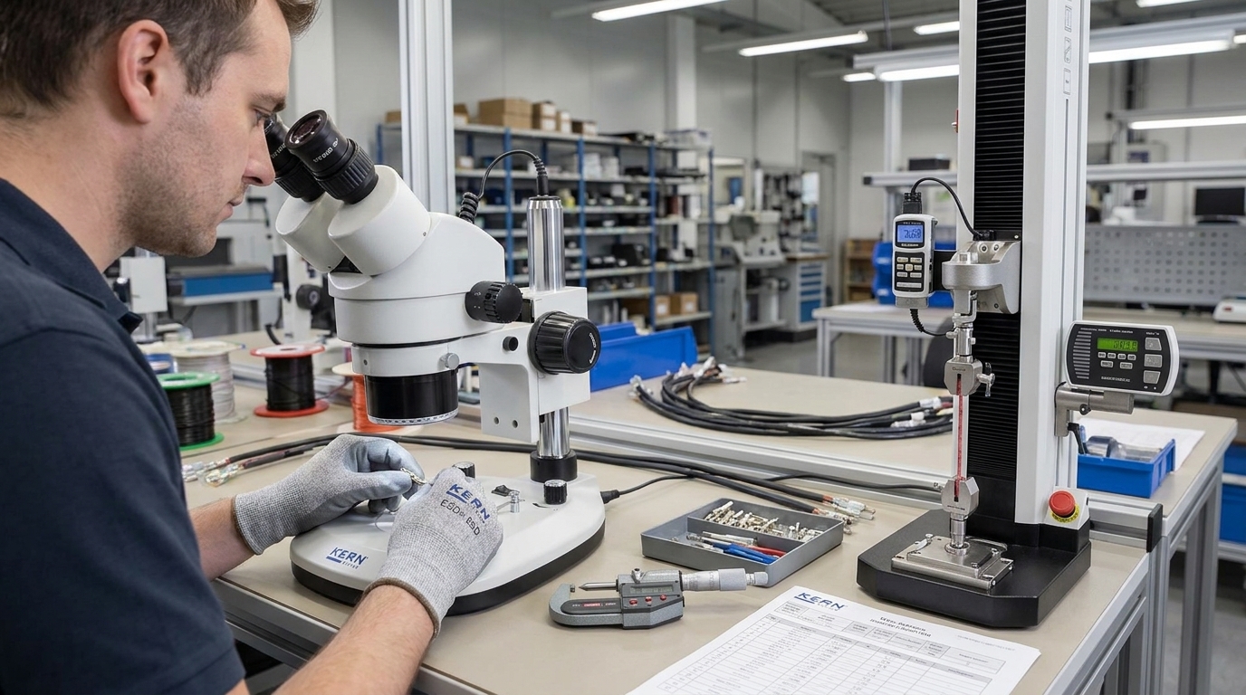 Crimp Connector Failures: Strip Length, Tooling, and Pull-Test ChecksUTMEL20 October 202621
This technical guide diagnoses wire crimp connector failures and outlines a complete shop-floor verification workflow. It covers matching conductor and insulation barrels to wire specifications, distinguishing strip-length errors from insertion-depth mistakes, and inspecting bellmouths and anvil impressions. Finally, it pairs non-destructive crimp height measurements with IPC/WHMA-A-620 tensile pull-force testing and a three-stage sampling protocol to prevent latent field failures.
Read More The Introduction to USB Type-C Pin Signal and PCB LayoutUTMEL03 December 202127640
Hello everyone. Welcome to the new post today. USB Type-C is a smaller-volume USB interface standard than Type-A and Type-B. It can be used on a PC (master device) as well as external devices (slave devices, such as mobile phones).
Read More Everything You Need to Know about ConnectorsUTMEL07 September 20218798
Electrical connectors, as key components for current or signal connections, are also an important part of the industrial system. Connectors can be as huge as airplanes and rockets or as small as mobile phones and televisions, forming bridges between circuits or other components and serving as electric current or signal links.
Read More Network Interface Card: Types, Functions and Buying GuideUTMEL17 August 202111111
Network Interface Card (NIC, also known as a network interface controller) is one of the most basic components in the local area network. It is the hardware device connecting the computer and the network. Whether it is a twisted pair connection, a coaxial cable connection, or an optical fiber connection, data communication must be realized with the help of a network interface card.
Read More
Subscribe to Utmel !
![MI991EF]() MI991EF
iBASE Technology
![MI808F-300]() MI808F-300
iBASE Technology
![MI990VF-X28E]() MI990VF-X28E
iBASE Technology
![AMO-HSDPA02E]() AMO-HSDPA02E
Advantech Corp
![EWM-W157H01E]() EWM-W157H01E
Advantech Corp
![MI990EF-6100E]() MI990EF-6100E
iBASE Technology
![GFX-NG750TIL16-5C]() GFX-NG750TIL16-5C
Advantech Corp
![GFX-NG1050F16-5D1]() GFX-NG1050F16-5D1
Advantech Corp
![GFX-AR560F16-5K]() GFX-AR560F16-5K
Advantech Corp
![GFX-AE8860F16-5K]() GFX-AE8860F16-5K
Advantech Corp