
 Product
 Brand
Brand Articles
 Tools
Tools
What is FPC (Flexible Printed Circuit)?
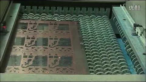
Flexible printed circuit manufacturing procedure
Catalog
| Ⅰ Overview |
| Ⅱ FPC composing material |
| Ⅲ FPC production process |
| Ⅳ FPC advantages and disadvantages |
| Ⅴ FPC soldering operation steps |
Ⅰ Overview
FPC, also known as Flexible Printed Circuit, is favored for its lightweight profile, minimal thickness, and capability for free bending and folding. As we advance through 2025, the electronics industry demands circuit board designs with unprecedented precision and density. Traditional manual inspection methods can no longer meet modern production needs, making Automated Optical Inspection (AOI) for FPC defects an inevitable standard in industrial development.

FPC
Flexible Printed Circuit (FPC) technology was originally developed by the United States for space rocket applications in the 1970s. However, today it is the backbone of consumer electronics, 5G communications, and automotive systems. It is made of polyester film, polyimide, or modern Liquid Crystal Polymer (LCP) substrates that offer high reliability and excellent flexibility. By embedding a circuit design on a flexible thin plastic sheet, precision components can be stacked in narrow, limited spaces to form a flexible circuit. This allows circuits to be bent, folded, or rolled, offering significant advantages in weight reduction, heat dissipation, and 3D installation capability. In 2025, Flexible Printed Circuits remain the primary solution for meeting the miniaturization and mobility requirements of smartphones, wearables, and electric vehicles (EVs).
Ⅱ FPC composing material
1. Insulating film
The insulating film forms the base layer of the circuit, and the adhesive bonds the copper foil to the insulating layer. In a multi-layer design, it is then bonded to the inner layer. These films also serve as a protective cover (Coverlay) to insulate the circuit from dust and moisture and to reduce stress during flexing.
In some flexible circuits, rigid components made of aluminum or stainless steel (stiffeners) are used to provide dimensional stability, physical support for component placement, and stress relief. The adhesive bonds the rigid component and the flexible circuit together. Additionally, modern "adhesiveless" laminates are increasingly popular in 2025, where the copper is directly deposited onto the film to reduce thickness and improve thermal performance.
There are several types of insulating film materials, with the most common being Polyimide (PI), Liquid Crystal Polymer (LCP), and Polyester (PET).
Polyimide (PI): Remains the dominant material, used in approximately 65-70% of high-reliability applications due to its non-flammability, geometric stability, and high tear strength. It can withstand high soldering temperatures.
Liquid Crystal Polymer (LCP): Has seen rapid adoption in the 5G era due to its low moisture absorption and excellent high-frequency signal integrity, superior to traditional PI.
Polyester (PET): Still used for low-cost applications. It has a lower dielectric constant but is not resistant to high temperatures (melting point ~250°C), limiting its use in environments requiring extensive soldering.
2. Conductor
Copper foil is the standard conductor for flexible circuits. It is categorized mainly into two types: Electrodeposited (ED) and Rolled Annealed (RA). ED copper has a glossy surface on one side and a matte surface on the other to improve bonding. However, RA copper is preferred for dynamic flexing applications (such as in folding phones) due to its superior ductility and resistance to fatigue cracking.
3. Adhesive
Adhesives are used to bond the insulating film to the conductive material or as a cover layer. Common types include acrylics and epoxies. However, a significant trend in modern FPC manufacturing is the shift toward Adhesiveless FPC. Laminates without adhesives form thinner circuits with greater flexibility and better thermal conductivity. By eliminating the thermal resistance of the adhesive layer, these circuits can operate in higher-temperature environments where traditional adhesive-based laminates might fail.
Ⅲ FPC production process
Double panel circuit board
Cutting → Drilling (Laser/Mechanical) → PTH (Plated Through Hole) → Electroplating → Pre-treatment → Dry Film Pasting → Alignment → Exposure → Development → Graphic Plating → Stripping → Pretreatment → Dry Film Pasting → Alignment Exposure → Development → Etching → Stripping → Surface Treatment → Paste Coverlay → Pressing/Curing → Immersion Gold (ENIG) → Printing Characters → Shearing → Electrical Test (AOI/Flying Probe) → Punching → Final Inspection → Packaging → Shipment
Single panel circuit board
Cutting → Drilling → Pasting Dry Film → Aligning → Exposure → Developing → Etching → Stripping → Surface Treatment → Covering Film → Pressing → Curing → Surface Treatment → Immersion Gold (ENIG) → Printing Characters → Cutting → Electrical Measurement → Punching Cutting → Final Inspection → Packaging → Shipment
Ⅳ FPC advantages and disadvantages
Advantages of Flexible Printed Circuits

FPC
Flexible printed circuit boards offer distinct advantages over rigid PCBs, particularly in the era of IoT and electric mobility:
1. 3D Interconnectivity: They can be bent, wound, and folded freely, allowing for arbitrary arrangement in 3D space. This is critical for foldable smartphones and complex automotive dashboard assemblies.
2. Miniaturization & Weight Reduction: FPC implementation drastically reduces volume and weight. In Electric Vehicles (EVs), FPCs are replacing heavy copper wire harnesses in Battery Management Systems (BMS), contributing to extended driving range.
3. Reliability & Heat Dissipation: FPCs offer excellent heat dissipation and solderability. The "Rigid-Flex" combination design further enhances capability by merging the stability of rigid boards with the flexibility of FPC, used extensively in aerospace and military optics.
Disadvantages of Flexible Printed Circuits
1. High Initial Cost: The NRE (Non-Recurring Engineering) costs for photographic masters, dies, and tooling are higher than rigid PCBs. It is generally not cost-effective for small-volume runs unless the flexibility is mandatory.
2. Difficult Rework: Once manufactured, FPCs are difficult to modify. The protective coverlay must be removed for repair and restored afterward, which is a delicate process prone to damaging the thin traces.
3. Handling Sensitivity: FPCs are susceptible to damage during assembly. Improper handling by personnel can tear the substrate or crack traces. Automated assembly requires specialized fixtures to prevent warpage.
Ⅴ FPC soldering operation steps
Note: While mass production utilizes SMT Reflow technology, the following steps outline the procedure for manual soldering or rework.
1. Before soldering, apply flux to the pad. Unlike rigid boards, ensure the soldering iron temperature is controlled (approx. 300°C-350°C) to prevent delamination of the thin FPC substrate. Pre-tinning pads can help avoid poor connectivity.
2. Use tweezers to carefully place components (e.g., QFP chips) onto the FPC. Alignment is critical as FPC pads do not have the mechanical rigidity of FR4 boards. Tack-solder diagonal pins to fix the chip in position, then recheck alignment before proceeding.
3. When soldering pins, apply flux to keep them moist and ensure smooth solder flow. The "drag soldering" technique is effective here. Critical Rule: Heat the pad, not the FPC film directly, to avoid burning the polyimide or LCP material.
4. After soldering, inspect for short circuits or "solder bridges," which are common on fine-pitch FPC components. Remove excess solder with wick if necessary. Clean the area with alcohol and a soft brush—avoid harsh scrubbing that could lift the pads.
5. For SMD resistance-capacitance components, tin one pad first. Slide the component into the molten solder using tweezers, align it, and then solder the opposite end. This reduces thermal stress on the flexible substrate.
 UTMEL
UTMEL
We are the professional distributor of electronic components, providing a large variety of products to save you a lot of time, effort, and cost with our efficient self-customized service. careful order preparation fast delivery service
1.What are flexible circuits used for?
Flexible circuits have evolved and helped provide durability and reliability. Flexible circuits are also used in the aviation field. Other applications of flexible circuits are hearing aids, calculators, cameras, printers, and satellites.
2.What are the advantages of flexible PCB?
A reduced number of interconnects reduces the potential number of failure points within a design. Flex circuit's ductility and low mass reduce the impact of vibration and shock and improve performance. Exceptional thermal stability of polyimide allows the circuit to withstand extreme heat applications.
3.How do you make a flexible circuit board?
DIY Flexible Printed Circuits Step 1: Get the copper-coated film. Get some thin sheets of polyimide which have copper on one or both sides. Step 2: Use a solid-ink printer. For direct printing on the copper film, locate a solid-ink printer. Step 3: Print on Pyralux. Step 4: Etch it. Step 5: Populate the board.
4.What is an FPC connector?
Flexible Printed Circuit (FPC) Connectors have been developed to meet the challenges of this expanding market, which demands smaller centerline or pitch spacing, lower profile heights, and lighter interconnect solutions. View video to explore FPC connectors' capabilities.
5.How do you solder a flexible printed circuit?
1.Start off by dabbing the contacts with flux; 2.Tin the tip of the soldering iron and clean the tip of the soldering iron on a wet sponge; 3.Put a dot of solder on the tip of the soldering iron; 4.Tin one of the copper solder pads; 5.Clean the tip of the soldering iron again on a wet sponge; 6.Put another dot of solder on the tip of the soldering iron; 7.Quickly touch the soldering iron to the tinned copper pad and sweep the tip of the iron up onto the accelerometer lead.
 Pull-Down Circuit Guide: Working Principle, Resistor Value, Circuit Design, and ApplicationsUTMEL26 June 2026165
Learn how pull-down circuits work, how to choose a pull-down resistor value, and how to design reliable microcontroller inputs, MOSFET gates, reset pins, and sensor interfaces.
Read More HF PCB Circuit Design 10 QuestionsUTMEL16 March 20225351
Hello everyone, I am Rose. Today I want to give you a full explanation about PCB design. I Hope the following ten questions will give you a satisfied answer.
Read More How Many do You Know About the 12 Components Included in the Circuit Board?UTMEL12 February 20228837
We are lucky to live in an era where electronic devices are readily available. These electronic devices, on the other hand, come to us thanks to the incredible components on the circuit board, and we frequently wonder what makes electronic devices operate, how they achieve such massive success, and how they accomplish it. Electronic devices are incredible things; you can't see what's going on within them, but you can see what they're capable of. We'll talk about the wonders of PCBs and how to get past them to construct the circuit board in this article.
Read More![50 Frequently Asked Questions about PCB Layout [Q&A]](https://res.utmel.com/Images/Article/b5ce2a0a-d37c-4243-aff3-df7b2da2db0f.jpg "50 Frequently Asked Questions about PCB Layout [Q&A]") 50 Frequently Asked Questions about PCB Layout [Q&A]UTMEL16 November 20217169
50 Frequently Asked Questions about PCB Layout [Q&A]UTMEL16 November 20217169In the design of electronic products, PCB layout and routing is an important step, and the quality of PCB layout and routing will directly affect the performance of the circuit.
Read More An Overview of Development BoardUTMEL18 December 202515403
The development board is a circuit board used for embedded system development. Development boards are generally customized by embedded system developers according to development needs.
Read More
Subscribe to Utmel !