
 Product
 Brand
Brand Articles
 Tools
Tools
What is Power Factor Correction (PFC)?
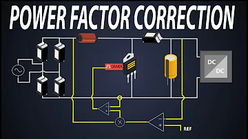
Power Factor Correction | Active Power Factor Correction | PFC Control | Boost PFC
Ⅰ. Power factor compensation and power factor correction
Improved approaches for the low power supply efficiency caused by the varied phases of the voltage and current of AC electrical appliances with inductive loads (Figure 1) were proposed in the 1950s (due to the current hysteresis of the inductive load). Voltage increases the load on the power supply line and reduces its efficiency because of the varying phases of voltage and current. To alter the voltage and current phase characteristics of the inductive electrical device, a capacitor must be connected in parallel with it.
For example, a 4.75F capacitor must be connected in parallel with a 40W fluorescent lamp at the time. A capacitor is connected in parallel to the inductive load, and the current leading voltage on its capacitance is utilized to compensate for the current lagging voltage on the inductor, bringing the overall characteristic closer to resistive and so improving the inefficiency. Power factor adjustment (alternating current) is the name of the technique. The cosine function value cos of the phase angle between the power source voltage and the load current can be used to express the power factor.

Figure 1
Ⅱ. Waveforms of voltage and current in the power supply line in an inductive load
However, high-efficiency switching power supply have been employed in a vast variety of electrical equipment since the 1980s. The load characteristics of electrical appliances are capacitive because switching power supply use a large-capacity filter capacitor after rectification. As a result of the charging and discharging actions of the filter capacitor, the DC voltage at both ends of the filter capacitor has a slightly sawtooth ripple when AC 220V gives power to the electric appliance. The voltage on the filter capacitor's minimum value is far from zero, while the maximum value is not significantly different (peak ripple). The rectifier diode will be turned on due to the forward bias only when the instantaneous value of the AC line voltage is higher than the voltage on the filter capacitor, and when the instantaneous value of the AC input voltage is lower than the voltage on the filter capacitor, according to the rectifier diode's unidirectional conductivity. Due to reverse bias, the rectifier diode is turned off when the voltage is higher.
In other words, the diode will only switch on near its peak value during each half cycle of the AC line voltage. Although the AC input voltage retains a sine wave shape in most cases, the AC input current exhibits high-amplitude spikes, as shown in Figure 2. This significantly distorted current waveform comprises a large number of harmonic components, resulting in a significant loss in the line's power factor.
The rectifier diode's conduction angle is substantially smaller than 1800 in the positive half cycle (1800), and it's only 300-700 in the negative half cycle (1800). A considerable conduction current will be created during the extremely narrow conduction angle due to the requirement of ensuring the load power. When the power supply line capacity is insufficient or the circuit load is large (Figure 3), pulse the power supply current in the power supply circuit, it not only reduces the efficiency of the power supply, but it also produces serious AC voltage waveform distortion and generates multiple harmonics, interfering with the normal operation of other electrical appliances (this is electromagnetic interference-EMI and electromagnetic compatibility-EMC issues).

Figure 2
Since inductive loads were utilized in the past (early televisions, radios, and other electrical appliances all used inductive devices with power transformers), the notion of power factor correction has expanded to include rectifier and filter capacitors. The problem of varied voltage and current phases is particularly problematic when trying to tackle electromagnetic interference (EMI) and electromagnetic compatibility (EMC) issues caused by the power supply current's strong pulse condition.
This is a brand-new technology that was invented at the turn of the century (its background stems from the rapid development and wide application of switching power supplies). Its major goal is to overcome the problems of electromagnetic interference (EMl) and electromagnetic compatibility (EMC) produced by the capacitive load's extreme distortion of the current waveform. As a result, modern PFC technology differs significantly from previous power factor adjustment technologies. It is used to correct non-sinusoidal current waveform distortion by forcing the AC line current to follow the voltage waveform's instantaneous change trajectory and keeping the current and voltage in phase, giving the appearance of pure resistive technology (line current waveform correction technology) (power factor correction).
As a result, modern PFC technology completes the current waveform rectification while simultaneously addressing the issue of in-phase voltage and current.

Figure 3
For the reasons stated above, capacitive load electrical appliances requiring more than 85W (some data suggest greater than 75W) must include a correction circuit to rectify the load characteristics and bring them closer to resistive load characteristics (voltage and current waveforms are in phase And the waveform is similar). The modern power factor correction (PFC) circuit looks like this.
Ⅲ. The hazards of capacitive loads
A half-wave rectifier circuit without a filter capacitor is shown in Figure 4, and a half-wave rectifier circuit with a large-capacity filter capacitor is shown in Figure 5. On the basis of these two circuits, we study the current waveforms in the two circuits.

Figure 4
The rectifier is D, and the load is R in A. When the circuit is linked to alternating current, Figure 4B shows the waveform diagram of the voltage and current in the circuit.
At (001800) t0t3 time, the voltage is zero at time t0 and the current is zero; at time t1, the voltage reaches its maximum and the current also reaches its maximum; at time t3, the voltage is zero and the current is zero; and at time t3, the voltage is zero and the current is zero. (The diode has a conductivity of 1800)
The diode is reverse biased without voltage or current at (18003600) t3t4: time. (Cut-off diode)
At (36005400) time t4t6, the voltage and current are both zero at time t4, the voltage reaches its maximum at time t5 and the current also reaches its maximum, and the voltage and current are both zero at time t6. (The diode has a conductivity of 1800)
Conclusion: The voltage and current of the power supply circuit are in phase in a rectifier circuit without a filter capacitor, and the diode conduction angle is 1800. The circuit for the power supply circuit has a purely resistive load characteristic.

Figure 5
D is a rectifier tube, R is a load, and C is a filter capacitor in Figure 5A. When the circuit is linked to alternating current, Figure 5B shows the waveform diagram of the voltage and current in the circuit.
At (001800) t0t3 time, the voltage is zero at time t1 and the current is zero; nevertheless, at time t1, the voltage reaches its maximum value and the current likewise reaches its maximum value, because the capacitor C is being charged at the same time as the load R. As a result, the current's magnitude is quite large. The capacitor C is charged at time t1, and the capacitor's voltage Uc approaches the peak value of the input alternating current. The voltage on the right side of the diode is Uc during t1t3, and the voltage on the left side progressively varies from the highest value at t2. The diode is reverse-biased off at t1t3 when it lowers to zero, and the current is zero during this time. (For the first positive half cycle of the alternating current, the diode's conduction angle is 900 after adding the filter capacitor C.)
The diode is reverse biased without voltage or current during the (18003600) t3t4 period. (Cut-off diode)
t4t5 at (36004100): The voltage on C is discharged through the load because the diode is reverse biased at t3t4, and the voltage progressively lowers (the magnitude of the decline is determined by the capacity of C and the resistance of R). Uc lowers very slowly if C's capacity is great enough and R's resistance is also large enough.) During t4t5, the voltage on the left side of the diode steadily rises, but the voltage Uc on the right side remains constant due to the slow discharge of Uc on the right side of the diode. Although the diode is larger than the left, it is still reverse-biased and cut off.
At (41005400) t5t7, the voltage on the left side of the diode rises to exceed the voltage on the right side at t5. The diode turns on to charge C and give electricity to the load. The diode has a significant current running through it. The voltage on the diode's left side progressively lowers at t6. During t6t7, the diode reaches the reverse bias cut-off once more because Uc is charged to its maximum value.
Conclusion: The voltage and current waveforms of the power supply circuit are radically different in a rectifier circuit with a filter capacitor. In a brief period of time, the current waveform displays a strong pulse condition. The conduction angle of the diode is less than 1800 degrees (according to the load R and the filter capacitor C). Constant time). During the extremely brief duration of the intense current pulse, this circuit has a large voltage drop (particularly significant for power supply lines with large internal resistance), causing the voltage waveform of the power supply line to be distorted. Other electrical appliances are severely harmed by high-order harmonics.
Ⅳ. How to perform power factor correction
Power factor correction (PFC):
The TV set we presently use has a high-efficiency switching power supply, and the internal power input section of the switching power supply employs a diode full-wave rectification and filter circuit, as illustrated in Figure 6A, with its voltage and current waveforms in Figure 6B.

Figure 6
6A 6B
Modern electrical appliances with higher power (more than 85W) with switching power supply (capacitive load) must use PFC measures, such as PFC, active PFC, and passive PFC Way, to reduce current waveform distortion and enhance power factor.
Some manufacturers do not currently use correcting circuits made up of active elements like transistors. It is primarily made up of passive components including diodes, resistors, capacitors, and inductors. Add an inductor between the rectifier bridge and the filter capacitor (appropriate selection Inductance) to current domestic TV manufacturers for TVs with higher power designed in the past, using the characteristic that the current on the inductor can't change abruptly to smooth the fluctuation of the strong pulse of capacitor charging, improve the distortion of the current waveform of the power supply line, and the characteristic of the inductance of the voltage le, Electromagnetic compatibility and electromagnetic interference are factors that can be improved, as shown in Figure 7.

Figure 7
Although this circuit is basic, you can simply add a sufficient inductance (appropriately pick the values of L and C) to equipment without PFC function designed in the early stages to accomplish the PFC function, but this simple, low-cost solution is more efficient. The output ripple of a passive PFC is high, the DC voltage across the filter capacitor is low, current distortion correction and power factor compensation capabilities are poor, and the L winding and quality control of the iron core are poor. The severe interference created by the image and accompanying sound can only be employed as a stopgap measure for early market introduction without PFC equipment.
Ⅴ. Principle of active PFC circuit
Active PFC has a favorable effect; it can practically entirely eliminate current waveform distortion and manage the phase of voltage and current to be consistent; it can basically totally solve power factor, electromagnetic compatibility, and electromagnetic interference concerns. However, the circuit is extremely intricate. After the 220V rectifier bridge stack, the primary idea is to remove the filter capacitor (to eliminate the current waveform distortion and phase change caused by the charging of the capacitor). When the filter capacitor is removed, a "chopper" circuit is formed. The pulsating DC is converted to high-frequency (approximately 100K) AC, and the DC voltage is then delivered to a traditional PWM switching stabilized power supply after rectification and filtering. The process is: AC→DC→AC→DC.
The main idea behind active PFC is to put a DC-DC chopper circuit between the switching power supply's rectifier circuit and the filter capacitor. Figure 8 (additional switching power supply). Because the rectifier circuit's output is not directly connected to the filter capacitor for the power supply line, it provides a fully resistive load to the power supply line, and its voltage and current waveforms are in phase and phase. The work of the chopper circuit is likewise similar to a switching power supply. As a result, the active PFC switching power supply is a dual-switching power supply circuit made up of a chopper (dubbed "PFC switching power supply") and a regulated switching power supply (dubbed "PWM switching power supply" from now on).

Figure 8
Ⅵ. Chopper part (PFC switching power supply)
After the rectifier diode is rectified, no filter capacitor is added, and the unfiltered pulsating positive half-cycle voltage is used as the power supply of the chopper. Due to the series of "switching" work of the chopper, the pulsating positive voltage is "chopped" into the figure 9 The characteristics of the current waveform are:
1. The current waveform is discontinuous, and its envelope is the same as the voltage waveform, and the phase of the envelope and the voltage waveform is the same.
2. Due to the effect of chopping, the half-wave pulsating DC power becomes high-frequency (determined by the chopping frequency, about 100KHz) "AC" power. This high-frequency "AC" power must be rectified again before it can be stabilized by the subsequent PWM switch. Voltage source is used.
3. From the general perspective of external power supply, the power system achieves that the AC voltage and AC current are in phase and the voltage and current waveforms are in line with the sinusoidal waveform, which not only solves the problem of power factor compensation, but also solves electromagnetic compatibility (EMC) and electromagnetic interference ( EMI) problem.
This high-frequency "AC" power is rectified by a rectifier diode and filtered into a DC voltage (power supply) to supply power to the subsequent PWM switching power supply. This DC voltage is called B+PFC (TPW-4211 is the case) in some materials. The B+PFC voltage output by the chopper is generally higher than the original 220 AC rectifier filtered +300V. The reason is It is to choose high voltage, its inductance wire diameter is small, the line voltage drop is small, the filter capacitor capacity is small, and the filtering effect is good, it has many advantages such as low requirements for the downstream PWM switch tube. Black is the voltage waveform, the red dashed line is the current envelope waveform

Figure 9
At present, in the PFC switching power supply part, the chopper tube (K), which plays the role of a switch, has two working modes:
1. Continuous conduction mode (CCM): The operating frequency of the switching tube is constant, and the duty cycle (coefficient) of conduction changes with the amplitude of the chopped voltage, as shown in Figure 10. The positions of T1 and T2 in the figure are : T1 is in the low voltage area of the chopped voltage (half cycle), T2 is in the high voltage area of the chopped voltage, T1 (time) = T2 (time) From the figure, it can be seen that all switching cycle times are equal, This shows that at any amplitude of the chopping voltage, the operating frequency of the chopper tube remains unchanged, as can be seen from Figure 10; the duty cycle of each chopping cycle is different in the high-voltage region and the low-voltage region (T1 The time is the same as T2, but the width of the rising pulse is different), when the chopping voltage is zero (no voltage), the chopping frequency remains the same, so it is called continuous conduction mode (CCM). This mode is generally used at 250W ~2000W equipment.

Figure 10
2. Discontinuous conduction mode (DCM): The operating frequency of the chopper switch tube changes with the size of the chopped voltage (the "on" and "off" times in each switching cycle are equal. As shown in Figure 11: T1 and T2 times are different , It also reflects that the chopping frequency also changes with the change of the voltage amplitude. The chopping voltage is "zero" and the switch stops (the oscillation stops), so it is called discontinuous conduction mode (DCM), that is, there is input voltage chopping The tube works, the chopper tube does not work without input voltage. It is generally used in low-power equipment below 250W.

Figure 11
(3) Critical conduction mode (CRM) or transition mode (TCM):
The work is between CCM and DCM, and the work is closer to DCM mode. After the last conduction period ends and before the next conduction period, the inductor current will decay to zero, and the frequency will vary with line voltage and load changes.
Advantages: cheap chip, easy to design, no conduction loss of the switch, the choice of boost diode is not decisive;
Disadvantages: Due to frequency changes, there are potential EMI problems, and a precisely designed input filter is required.
 UTMEL
UTMEL
We are the professional distributor of electronic components, providing a large variety of products to save you a lot of time, effort, and cost with our efficient self-customized service. careful order preparation fast delivery service
1. What is PFC?
PFC (Power Factor Correction) refers to power factor correction, which is mainly used to characterize the utilization efficiency of electrical energy by electronic products. The higher the power factor, the higher the utilization efficiency of electric energy.
2. What is the difference between active pfc and passive pfc?
The difference between the two is that passive PFC technology generally uses inductance compensation to reduce the phase difference between the fundamental current and voltage of the AC input to increase the power factor. However, the power factor of passive PFC is not very high and can only reach Around 0 7-0 8. Active PFC is composed of inductors, capacitors and electronic components. It is small in size and can achieve a high power factor, but the cost is higher than that of passive PFC.
3. What is the role of PFC circuit in switching power supply?
Switching power supply is a capacitor input type circuit. The phase difference between its current and voltage will cause the loss of exchange power. At this time, a PFC circuit is needed to improve the power factor.
 LLC Converter with Planar Matrix Transformer for High-Current-High-Power ApplicationsSaumitra Jagdale15 March 20244892
The rise of data centres in recent years, driven by cloud computing and big data, has caused a significant increase in electricity consumption. In the United States alone, it exceeded 70 billion kWh by 2014, making up 1.8% of total national electricity usage.
Read More Norton's Theorem: Working Principle, Circuit Design, and Modern ApplicationsUTMEL27 May 2026438
Norton's theorem simplifies complex linear electrical networks into an equivalent circuit containing a single current source in parallel with a resistor. This article explains the essential five-step workflow for calculating Norton parameters, compares it to its dual, Thévenin's theorem, and explores modern applications in power distribution networks, electric vehicle battery management, and fault diagnosis.
Read More SiC and GaN in 2026:How SiC and GaN Power Devices are Redefining AI Data Centers and 800V EVsUTMEL16 June 2026857
As AI data centers and 800V EVs hit physical thermal limits, the power electronics industry is shifting toward wide-bandgap semiconductors like SiC and GaN. This article explores how these materials are deployed in hybrid topologies to redefine power distribution, detailing high-voltage direct current architectures, engineering challenges in gate driving, and strategic sourcing solutions to build highly efficient, reliable modern power systems.
Read More Enhancing Frequency Stability in Modern Distributed Power SystemsRakesh Kumar, Ph.D.21 September 20244326
The article discusses the importance of primary frequency regulation in maintaining grid stability. It also explores battery energy storage systems, virtual synchronous generators, and advanced control strategies to enhance frequency stability in power systems.
Read More The Impact of SMPS on LED Lighting and Diverse IndustriesUTMEL05 June 20252673
Switched-Mode Power Supplies (SMPS) enhance LED lighting and industries by improving energy efficiency, reliability, and sustainability across diverse applications.
Read More
Subscribe to Utmel !
![RPM31P7]() RPM31P7
RPM31P7Schneider Electric
![J7KN-210-24]() J7KN-210-24
J7KN-210-24Omron Automation and Safety
![3RT20251AF04]() 3RT20251AF04
3RT20251AF04Siemens
![JW1AFSN-DC5V-F]() JW1AFSN-DC5V-F
JW1AFSN-DC5V-FPanasonic Electric Works
![AHES3191]() AHES3191
AHES3191Panasonic Electric Works
![34.51.7.005.0010]() 34.51.7.005.0010
34.51.7.005.0010Finder Relays, Inc.
![DRC3P48D420]() DRC3P48D420
DRC3P48D420Sensata-Crydom
![RXM3AB2FD]() RXM3AB2FD
RXM3AB2FDSchneider Electric
![3RH21221AF00]() 3RH21221AF00
3RH21221AF00Siemens
![RXM4AB2FD]() RXM4AB2FD
RXM4AB2FDSchneider Electric


