
 Product
 Brand
Brand Articles
 Tools
Tools
Why Your Power Supply Ripple Is So Big?
Power supply ripple and how to measure it
| Topics covered in this article: |
| Ⅰ. What is a ripple? |
| Ⅱ. Why your power supply ripple is so big? |
| Ⅲ. Problem analysis |
| Ⅳ. Problem summary |
Ⅰ. What is a ripple?
Because the DC stable power supply is generally formed by the AC power supply through rectification and voltage regulation and other links, it is inevitable in the DC stable amount with some AC components, this kind of superimposed on the DC stable amount of THE AC component is called ripple. The composition of ripple is more complex, its shape is generally higher than the frequency of the similar sinusoidal harmonic wave, the other is a very narrow width pulse wave. For different occasions, the requirements of ripple are different.
Ripple can be expressed by effective value or peak value, absolute value or relative value. For example, a power supply working in a stable voltage state, its output is 100V 5A, the measured ripple effective value is 10mV, this 10mV is the absolute amount of ripple, and the relative amount is ripple coefficient = ripple voltage/output voltage = 10mV /100V=0.01%, equal to 1/10,000.
Ⅱ. Why your power supply ripple is so big?
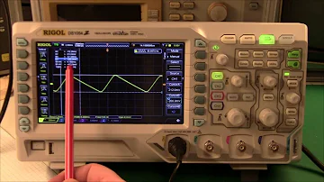
When a user tested the ripple of 5V signal output from his switching power supply with a 500MHz bandwidth oscilloscope, it was found that the peak-to-peak value of ripple and noise reached more than 900 mV (as shown in the figure below), while the peak-to-peak value of the nominal ripple of his switching power supply was < 20mV. Although there is LDO on the back stage of the user circuit board to stabilize the output voltage of the switching power supply. the user thinks that the measured result is too large and not very reliable, and hopes to find out the problem.

Figure. 1
Ⅲ. Problem analysis
The problem of large power ripple test is usually related to the probe used and the way the front end is connected. Firstly, the connection mode of the user probe was checked. It was found that the long crocodile clip ground wire was used as shown in the left figure below, and the ground point was clamped on the fixed screw of the single board. The whole ground loop was relatively large. Since the larger ground loop will introduce more space electromagnetic radiation noise and ground loop noise caused by the switching power supply. the short ground spring pin is replaced as shown in the figure on the right below.

Figure. 2
After practical testing, it is found that the peak-to-peak value of measured ripple noise has been greatly improved, as shown in the figure below. But the ripple noise peak-to-peak value is still more than 40 mV, and the switch power supply manufacturer's nominal <20mV is still a big difference.

Figure. 3
Further check the user's probe model, found that the user is using the oscilloscope standard with 10:1 passive probe. As shown in the figure below.

Figure. 4
The 10:1 probe will attenuate the measured signal by 10 times and then feed it into an oscilloscope, which will then mathematically amplify the measured signal by 10 times. The advantage of this probe is through the front of the matching circuit to improve the probe bandwidth to several hundred MHz, and expand the scope of the oscilloscope, but for small signal measurement is not special advantage. If the measured signal amplitude itself is small, another 10 times of attenuation may be submerged in the oscilloscope noise, even if another 10 times of mathematical amplification, for the signal-to-noise ratio itself is not improved. Therefore, the measurement of power ripple noise should try to use a probe with a small attenuation ratio, such as 1:1 probe. So another 1:1 passive probe is found, this 1:1 passive probe although the bandwidth is not high (usually dozens of MHz), but the attenuation ratio is small, very suitable for small signal test.
The following figure shows the comparison test results of 1:1 passive probe and 10:1 probe under different bandwidth limits. It can be seen that after using 1:1 probe and setting 20MHz bandwidth limit, the measured ripple noise peak-to-peak value is less than 10mV, which is much better than the test result of 10:1 probe. From the test results of 1:1 probe, we can see clear ripple waveform, and meet the user's expectation for power ripple noise <20mV. In addition, we can also see that the bandwidth limit has a certain improvement effect on the peak-to-peak value of noise.

Figure. 5
Ⅳ. Problem summary
This is a typical power ripple test problem. We have greatly improved the ripple noise test results by using a short ground connection, switching to a probe with a low attenuation ratio, and bandwidth limiting. Generally speaking, the influencing factors of power ripple test results are as follows in terms of importance:
1. The front end of the connection line and the length of the ground loop: long ground loop will pick up more switching power supply electromagnetic radiation and ground noise, so the need to use as short as possible ground connection.
2. Probe attenuation ratio: large attenuation ratio of the probe will make the small signal amplitude more weak, even submerged in the oscilloscope noise, so should try to use 1:1 attenuation ratio of the probe.
3. Bandwidth limit: a lot of electromagnetic noise and oscilloscope noise are broadband, set the appropriate bandwidth limit can filter out the additional noise. Many power ripple noise testing applications use a bandwidth limit of 20MHz, while some chips require a bandwidth limit of 80MHz or 200MHz.
4. Measuring range: usually in a small range range (such as 10MV/grid or 20mV/grid) for power ripple test. The larger the range, the higher the noise of the oscilloscope. However, some oscilloscopes have a limited range of bias and may not be able to pull the measured DC voltage signal back to the center of the screen for measurement at a small tap. Therefore, the AC coupling function of oscilloscopes is often used to isolate the DC and then conduct ripple noise test.
5. Input impedance: many oscilloscopes have 50 ohm and 1M ohm input impedance choice, usually 50 ohm input impedance oscilloscopes bottom noise is lower. However, when the oscilloscope is connected to most passive probes, the impedance is automatically switched to 1M ohm, and only when the active probe or coaxial cable is connected can the input impedance be set to 50 ohm.
It is a good practice to check the background noise of the current device and system Settings before conducting actual tests. The five waveforms in the figure below are the bottom noise results of a 500M S series oscilloscope with different probe and bandwidth Settings. Waveform from top to bottom: 50 ohm input impedance, 1:1 probe, 500MHz bandwidth; 1M ohm input impedance, 1:1 probe, 20MHz bandwidth; 1M ohm input impedance, 1:1 probe, 500MHz bandwidth; 1M ohm input impedance, 10:1 probe, 20MHz bandwidth; 1M ohm input impedance, 10:1 probe, 500MHz bandwidth. The peak-to-peak value of the bottom noise is from less than 1mV to close to 30mV, indicating the importance of probe, bandwidth and input impedance setting in the test.

Figure. 6
If you really don't have a suitable low attenuation ratio probe on hand, you can also make a homemade probe using 50 ohm coaxial cable as follows. In effect, one end of the cable is connected to an oscilloscope set to 50 ohm input impedance; The other end of the cable is peeled off, the shield layer is welded to the ground of the circuit under test, and the central conductor is connected to the power signal under test through a straight capacitor. The advantages of this method are low cost and low attenuation ratio, but the disadvantages are poor consistency, and the parameters of isolated capacitance and bandwidth are not well controlled. In addition, in recent years, oscilloscope manufacturers have also launched probes specially designed for power ripple test, which combine low attenuation ratio (1.1:1), high bandwidth (hardware 2GHz, bandwidth limit can be set by software), and impedance matching of measurement needs and noise (the dc input impedance of the probe itself is 50K ohm, But oscilloscope end is 50 ohm input impedance spectrum), short ground wire (provides very low loop inductance welding front), large bias range (up to ±24V), ripple and DC voltage can be tested at the same time, suitable for the power ripple measurement requirements are relatively high users.

Figure. 7
 UTMEL
UTMEL
We are the professional distributor of electronic components, providing a large variety of products to save you a lot of time, effort, and cost with our efficient self-customized service. careful order preparation fast delivery service
1. How to solve the problem of large power ripple
Switching power supply to reduce ripple mainly in the following three aspects: 1, energy storage inductance. The larger the Q value of the energy storage inductor at the working frequency, the better. 2. Filter capacitor. ESR and ESL of filter capacitance are very important parameters, the lower the better, only pursuing capacity is far from enough. 3.Do a good job in PCB design.
2. How much is switching power supply output ripple ?
The output ripple is between 200mV and 50mV, and the full load cannot exceed this range.
3. How to reduce power supply ripple?
1. After the output of switching power supply, LDO filter is connected. This is the most effective way to reduce ripple and noise
2. Capacitor C or RC on the diode
3. Diode followed by inductor (EMI filtering)
 LLC Converter with Planar Matrix Transformer for High-Current-High-Power ApplicationsSaumitra Jagdale15 March 20244938
The rise of data centres in recent years, driven by cloud computing and big data, has caused a significant increase in electricity consumption. In the United States alone, it exceeded 70 billion kWh by 2014, making up 1.8% of total national electricity usage.
Read More Norton's Theorem: Working Principle, Circuit Design, and Modern ApplicationsUTMEL27 May 2026547
Norton's theorem simplifies complex linear electrical networks into an equivalent circuit containing a single current source in parallel with a resistor. This article explains the essential five-step workflow for calculating Norton parameters, compares it to its dual, Thévenin's theorem, and explores modern applications in power distribution networks, electric vehicle battery management, and fault diagnosis.
Read More SiC and GaN in 2026:How SiC and GaN Power Devices are Redefining AI Data Centers and 800V EVsUTMEL16 June 20261415
As AI data centers and 800V EVs hit physical thermal limits, the power electronics industry is shifting toward wide-bandgap semiconductors like SiC and GaN. This article explores how these materials are deployed in hybrid topologies to redefine power distribution, detailing high-voltage direct current architectures, engineering challenges in gate driving, and strategic sourcing solutions to build highly efficient, reliable modern power systems.
Read More Enhancing Frequency Stability in Modern Distributed Power SystemsRakesh Kumar, Ph.D.21 September 20244352
The article discusses the importance of primary frequency regulation in maintaining grid stability. It also explores battery energy storage systems, virtual synchronous generators, and advanced control strategies to enhance frequency stability in power systems.
Read More The Impact of SMPS on LED Lighting and Diverse IndustriesUTMEL05 June 20252698
Switched-Mode Power Supplies (SMPS) enhance LED lighting and industries by improving energy efficiency, reliability, and sustainability across diverse applications.
Read More
Subscribe to Utmel !
![2967662]() 2967662
2967662Phoenix Contact
![G2R-1-T-DC24]() G2R-1-T-DC24
G2R-1-T-DC24Omron Automation and Safety
![ADY30024]() ADY30024
ADY30024Panasonic Electric Works
![LY1F-DC12]() LY1F-DC12
LY1F-DC12Omron Automation and Safety
![FCA-410-1622M]() FCA-410-1622M
FCA-410-1622MTE Connectivity Aerospace, Defense and Marine
![SZR-MY4-1-DC24V]() SZR-MY4-1-DC24V
SZR-MY4-1-DC24VHoneywell Sensing and Productivity Solutions
![2967617]() 2967617
2967617Phoenix Contact
![LKP1AF-5V]() LKP1AF-5V
LKP1AF-5VPanasonic Electric Works
![JW1AFSN-DC5V-F]() JW1AFSN-DC5V-F
JW1AFSN-DC5V-FPanasonic Electric Works
![AHES3191]() AHES3191
AHES3191Panasonic Electric Works


