Product
 Brand
Brand Articles
 Tools
Tools
What Is a Shunt (Resistor)? How Current Sensing Works and How to Choose
What is a SHUNT? (Used to measure Current) + How to make a DIY version
When an engineer needs to know exactly how much current flows through a circuit, one of the oldest and most dependable tools is a small, carefully made resistor placed directly in the current path. That component is a shunt resistor. The current passing through it creates a tiny voltage drop, and because that drop tracks the current in a predictable way, reading the voltage tells you the current. This guide stays on the electrical, current-sensing meaning of the word: the resistor used to measure current. It walks through how the part works, why the way you connect it matters so much, how to weigh resistance against heat, and how to select one with accuracy in mind.
Throughout, the numbers are deliberately left to the documents that own them. Resistance values, sense-voltage targets, power ratings, and temperature behaviour belong on a manufacturer datasheet for the specific part you choose, so this article keeps the discussion qualitative and points you to where the figures live.
What a shunt resistor is and how it works
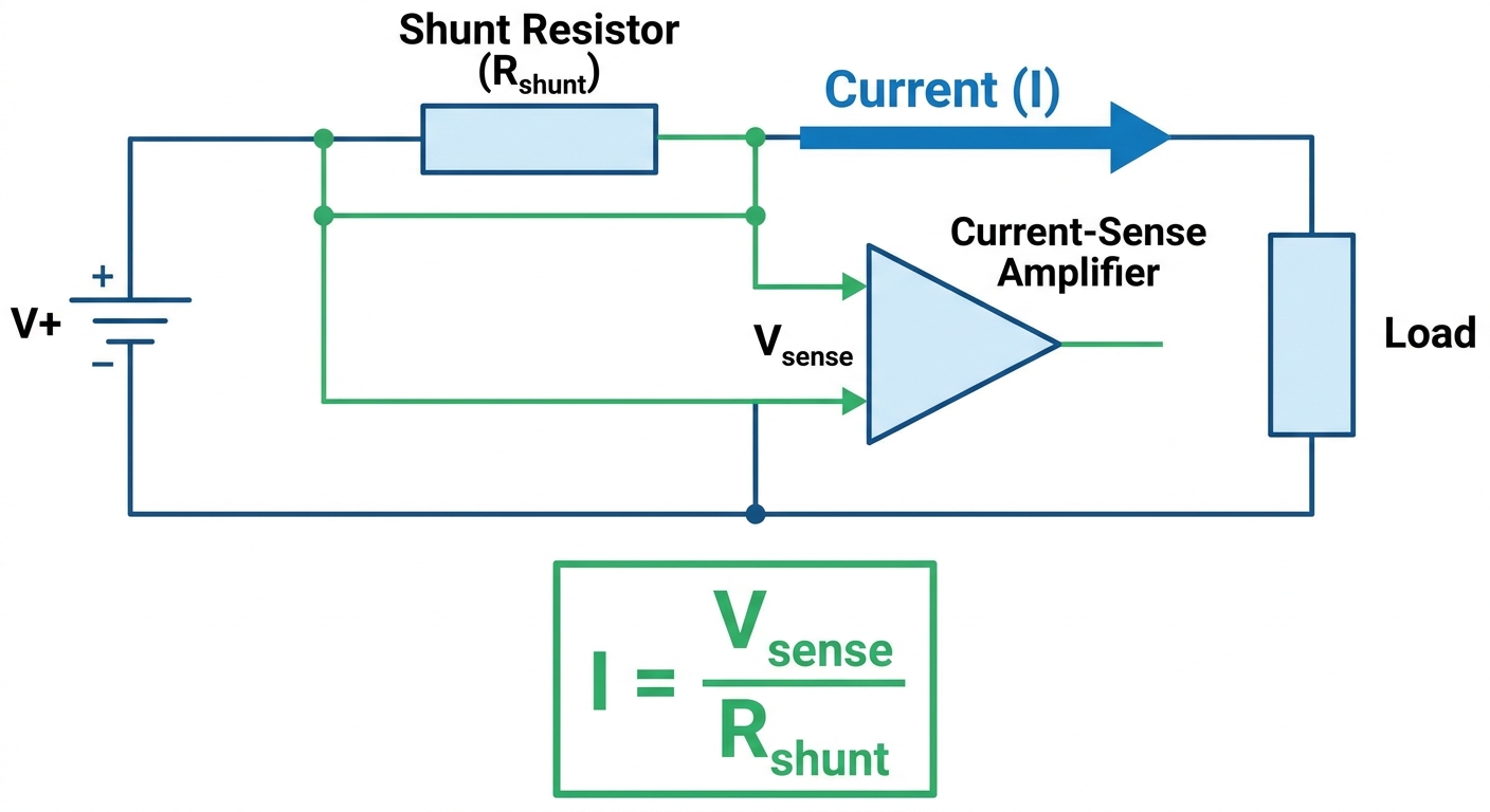
A shunt resistor is a low, precise resistance inserted in series with the load, so that all of the current you want to measure passes through it. As that current flows, it develops a small voltage across the resistor's terminals. Because the resistance is a known, stable quantity, the measured voltage is proportional to the current, and a meter or amplifier can convert that voltage back into a current reading. In other words, you are not measuring current directly; you are measuring a voltage that stands in for it.
The whole approach succeeds or fails on the quality of that resistance. A shunt is built to hold its value over temperature and over time, and to keep its own contribution to the signal as predictable as possible. Manufacturers such as Vishay, Bourns, Ohmite, TT Electronics (Welwyn), Isabellenhuette, and Riedon publish construction details, connection guidance, and selection notes for their precision and power shunt families, and those documents are the right place to confirm how a given part behaves in a real design.
Two ideas matter from the start. First, a shunt is intentionally a small resistance, because you do not want it to disturb the circuit it is measuring. Second, that small value is exactly what makes careful connection and careful thermal design so important, since at low resistance even tiny stray contributions can swamp the signal you care about. The rest of this guide builds on those two points.
Shunt resistor versus a "sense resistor"
People often ask whether a "shunt" and a "sense resistor" are different parts. In practice they describe the same idea working at different scales. Both are resistors placed in the current path whose voltage drop is used to measure current. The difference is usually one of scale and emphasis rather than physics.
The word "shunt" tends to be used for higher-current measurement, where the part is a substantial metal element designed to carry significant current and shed heat. The phrase "sense resistor" is more common on a circuit board, for smaller currents, often as a compact surface-mount component feeding a current-sense amplifier. The underlying principle is identical: a known resistance turns current into a measurable voltage.
Because the terms overlap, it helps to focus on the requirement rather than the label. Ask how much current the part must carry, how much voltage you want to develop for the measurement, and how much heat you can tolerate. Once those are clear, the choice between a bulky bolt-down element and a small board-mounted resistor follows naturally, and the naming becomes secondary.
Why the Kelvin (4-wire) connection matters
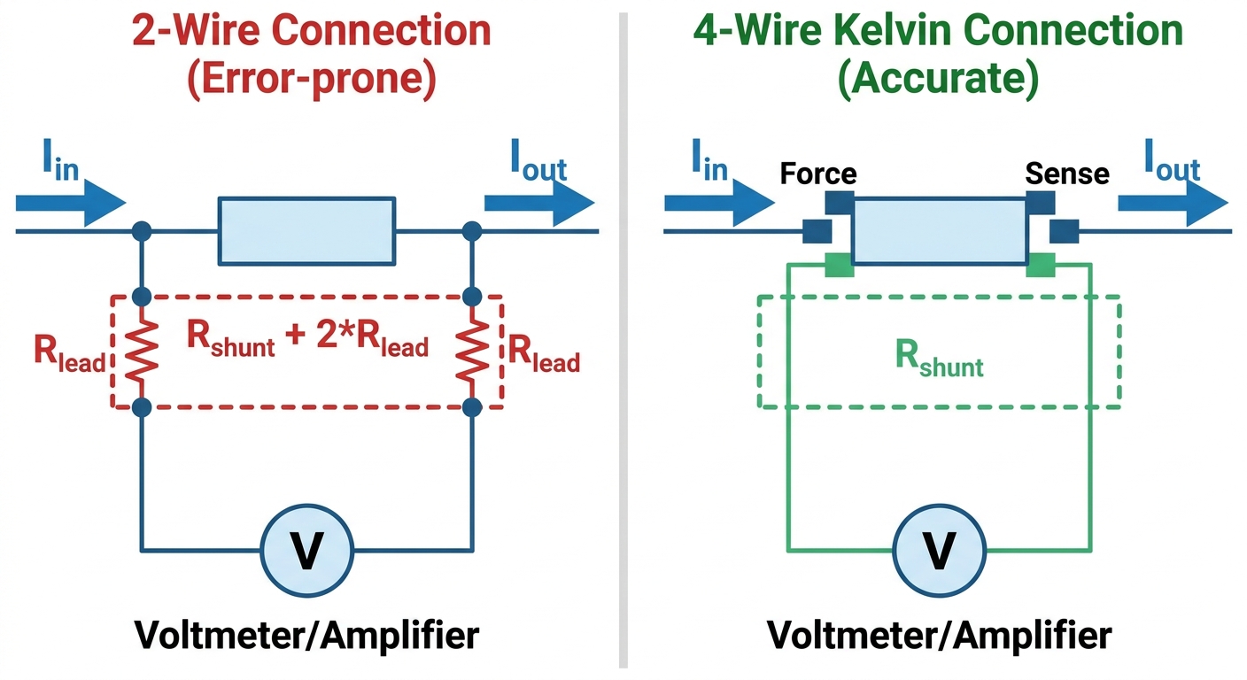
At the low resistances a shunt uses, the resistance of the wires, solder joints, and contacts leading to the part is no longer negligible compared with the part itself. If you measure the voltage across the same two terminals that carry the current, you also measure the drop across those leads and contacts, and that error rides along with your reading. The Kelvin, or four-terminal, connection is the standard cure.
In a Kelvin connection the current enters and leaves through one pair of terminals (the force or current terminals), while the measurement is taken from a separate pair of terminals (the sense terminals) connected as close as possible to the resistive element itself. Because almost no current flows in the sense path, the lead and contact resistance in that path drops essentially no voltage, so the meter sees the drop across the element and not across the wiring. Four-terminal shunts and four-terminal sense resistors are built specifically to make this separation clean.
Layout follows the same logic. The sense connections should tap the element symmetrically and as near to the resistive material as the part allows, the sense traces should be kept away from the high-current path so they do not pick up extra drop, and the high-current copper should be generous so it neither adds error nor becomes a hot spot. Manufacturer application notes for four-terminal parts describe the recommended footprint and sense-point placement, and following them is usually the difference between a measurement that holds its accuracy and one that drifts.
High-side versus low-side current sensing
Where you put the shunt in the circuit defines the sensing topology. In low-side sensing the shunt sits between the load and ground, so the measured voltage is referenced near ground. In high-side sensing the shunt sits between the supply and the load, so the measurement floats at the supply voltage. Both are valid, and each suits different goals.
Low-side sensing is simpler because the signal sits near ground, which keeps the measuring circuit straightforward. The trade-off is that the load no longer connects directly to ground; a fault that shorts the load to ground can bypass the shunt and go unseen, and the small ground-side drop slightly disturbs the load's reference. High-side sensing keeps the load grounded and can catch short-to-ground faults, but it asks the measuring circuit to work at the supply potential, which is where a dedicated current-sense amplifier earns its place.
A current-sense amplifier reads the small voltage across the shunt and presents a clean, scaled output, and high-side parts are designed to reject the large common-mode voltage at the supply rail. Application notes from suppliers such as Analog Devices, Texas Instruments, and ROHM lay out the signal chain for both topologies and explain where the amplifier fits, what common-mode range it needs, and how to keep the measurement quiet.
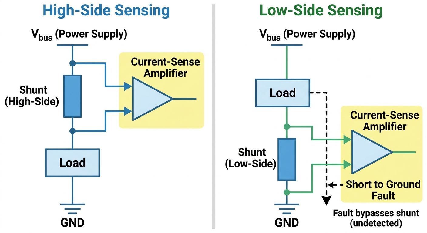
Figure 3: Circuit topologies for high-side sensing (left), where the shunt is placed between the supply and the load, and low-side sensing (right), where the shunt is placed between the load and ground.
| Consideration | Low-side sensing | High-side sensing |
|---|---|---|
| Shunt position | Between load and ground | Between supply and load |
| Measurement reference | Near ground, simpler to read | At the supply rail, needs common-mode rejection |
| Load grounding | Load no longer tied directly to ground | Load stays directly grounded |
| Short-to-ground fault | Can be missed because current bypasses the shunt | Detectable because current still passes the shunt |
| Typical amplifier need | Basic amplifier often sufficient | Dedicated high-side current-sense amplifier |
| Common use | Cost-sensitive, ground-referenced designs | Battery, motor, and fault-protection designs |
Choosing the resistance value
Picking the resistance is the central design decision, and it is a balancing act. A larger resistance produces a larger sense voltage, which is easier to read accurately and less vulnerable to noise and offset. But a larger resistance also dissipates more power at the same current, which means more heat, more self-heating drift, and a bigger disturbance to the circuit. A smaller resistance does the opposite: less heat and less disturbance, but a smaller, harder-to-read signal that demands a better amplifier and cleaner layout.
The practical method is to start from the measurement chain. Decide what sense voltage your meter or current-sense amplifier wants to see for good resolution at the currents you care about, then check the power and heat that the resulting resistance would produce at your maximum current. If the heat is too high, you either drop the resistance and lean on a more capable amplifier, or you keep the resistance and choose a physically larger, better-cooled part. The table below frames that trade-off qualitatively; the exact resistance, sense voltage, and power figures come from the datasheet of the part you settle on.
| If you raise the resistance | Effect on the measurement | Effect on power and heat |
|---|---|---|
| Larger sense voltage | Easier to read, better signal-to-noise, less sensitive to amplifier offset | More power dissipated, more heat to remove |
| Higher self-heating | Reading can drift as the element warms | Needs more thermal headroom or a larger part |
| More circuit disturbance | Slightly larger drop seen by the load | — |
| If you lower the resistance | Effect on the measurement | Effect on power and heat |
|---|---|---|
| Smaller sense voltage | Harder to read, more sensitive to noise and offset | Less power dissipated, less heat |
| Less self-heating | More stable reading under load | Easier thermal design |
| Less circuit disturbance | Load sees a smaller series drop | — |
A short selection checklist keeps the decision orderly:
Confirm the maximum continuous current and any peak or surge current the part must carry.
Set the target sense voltage from what your amplifier or meter reads cleanly.
Check the power dissipation at maximum current and compare it against the part's rating with derating applied.
Confirm there is enough thermal headroom, including airflow, copper area, and ambient temperature.
Verify the temperature coefficient and tolerance are tight enough for the accuracy you need.
Choose a four-terminal part and footprint where the resistance is low enough that lead and contact resistance would otherwise matter.
Read the chosen part's datasheet for the actual resistance, rating, and temperature figures before committing.
The parameters that drive accuracy
Once the resistance value is roughly set, accuracy comes down to a handful of parameters, and a shunt that ignores any of them can quietly undermine an otherwise careful design. The four that matter most are the power rating and its derating, the temperature coefficient of resistance, the tolerance, and self-heating.
The power rating tells you how much the part can dissipate, but it is almost always specified at a reference condition and must be derated as temperature rises or cooling weakens. Running a shunt near its limit invites drift and shortens its useful margin, so designers leave headroom. The temperature coefficient of resistance describes how much the resistance changes as the part warms, which directly shifts your reading; a low coefficient keeps the measurement honest across temperature. Tolerance is the spread of the resistance value from part to part, and it sets how much of your error budget is consumed before the circuit even powers up. Self-heating is the loop that ties these together: current creates heat, heat changes the resistance, and the changed resistance changes the reading, so a part with a low temperature coefficient and adequate thermal design keeps that loop small.
| Parameter | What it controls | Why it matters for accuracy |
|---|---|---|
| Power rating and derating | How much the part can safely dissipate, adjusted for temperature | Running near the limit invites drift and lost margin; headroom protects the reading |
| Temperature coefficient of resistance | How much resistance shifts with temperature | A high coefficient moves the reading as the part warms |
| Tolerance | Part-to-part spread of the resistance value | Consumes part of the error budget before operation begins |
| Self-heating | Resistance change caused by the part's own dissipation | Couples current, heat, and reading into a drift loop |
Manufacturer datasheets state these characteristics for each part, and reading them for the specific shunt you intend to use is the only reliable way to know the actual figures. The point here is the relationship between the parameters, not any particular number.
Common current-sensing mistakes
Most current-sensing problems trace back to a small set of avoidable errors, and recognising them early saves a lot of debugging. The first is measuring a low-value shunt with a two-wire connection. At low resistance the lead and contact drop is comparable to the signal, so a two-wire reading carries an error that no calibration of the resistor itself can remove; a four-terminal connection is the fix.
The second is ignoring self-heating. A shunt that reads correctly when cold can drift as it warms under load, and a design that never checks the part's temperature in operation can be fooled by a reading that slowly walks away from the truth. The third is applying the wrong power derating, by trusting the headline power rating without adjusting it for the real ambient temperature and cooling, which leaves the part running hotter and less stable than expected. The fourth is poor thermal layout, where thin copper, crowded placement, or a sense tap in the high-current path adds error or creates a hot spot. Generous high-current copper, a clean four-terminal sense tap, and attention to airflow address most of these at once.
Frequently asked questions
How do you measure current with a shunt resistor?
You place the shunt in series with the load so the full current flows through it, then measure the small voltage that appears across its sense terminals. Because the resistance is known and stable, that voltage is proportional to the current, and a meter or current-sense amplifier converts it into a current reading. At low resistance, a four-terminal connection is what keeps the reading trustworthy.
Is a shunt resistor the same as a sense resistor?
They are the same concept used at different scales. "Shunt" usually refers to a larger element for higher currents, while "sense resistor" often describes a smaller board-mounted part feeding an amplifier. Both turn current into a measurable voltage with a known resistance, so the right choice depends on the current, the desired signal, and the heat you can manage.
What is the ideal resistance value for a shunt?
There is no single ideal value; it is a trade-off. A higher resistance gives a larger, easier-to-read signal but dissipates more power and self-heats more, while a lower resistance runs cooler but produces a smaller signal that needs a better amplifier and cleaner layout. Set the value from the sense voltage your measuring circuit wants, then confirm the heat is acceptable on the part's datasheet.
How important is the power rating?
It is essential, but it must be read together with derating. The rated power applies at a reference condition and has to be reduced for higher ambient temperature and weaker cooling, so a sound design leaves thermal headroom rather than running at the limit. The datasheet for the specific part gives the rating and the derating curve to use.
Why use a four-terminal (Kelvin) connection?
Because at low resistance the wiring and contact resistance would otherwise add directly to your measurement. A four-terminal connection separates the current-carrying path from the sensing path, so the meter reads the drop across the element rather than across the leads. It is the standard way to keep a low-value shunt accurate.
When should I sense on the high side instead of the low side?
High-side sensing is the better fit when the load must stay directly grounded or when you need to catch faults that short the load to ground, which is common in battery and motor designs. It asks the measuring circuit to handle the supply-rail voltage, so it usually pairs with a dedicated high-side current-sense amplifier. Low-side sensing is simpler and often enough when those conditions do not apply.
Can I trust the resistance value across temperature?
Only as far as the part's temperature coefficient and thermal design allow. The resistance shifts as the element warms, and self-heating under load adds to that shift, so a low temperature coefficient and good cooling keep the reading stable. Confirm the coefficient and rating from the datasheet for the part you select rather than assuming a value.
Sources and references
The following references support the construction, connection, and selection ideas in this guide. They are starting points for the actual figures, which belong on the datasheet of the specific part you choose.
Vishay current-sensing and shunt resistor documentation confirms how precision and power shunt families are built and specified, and it is useful for understanding construction and ratings; its limitation is that the details are specific to Vishay parts, so figures do not transfer to other makers.
Bourns current sense resistor products shows how board-level sense resistors are characterised for tolerance and temperature behaviour, which helps when comparing parts; the catalogue is naturally oriented around Bourns offerings rather than a vendor-neutral overview.
Ohmite current sense and power resistor resources describe bolt-down and power-element shunts for higher-current measurement and their thermal considerations; because the material is product-led, it is best read as construction guidance rather than a general tutorial.
Isabellenhuette precision power resistors and shunts explain the four-terminal measurement approach and low-temperature-coefficient alloys behind accurate shunts; the focus is on this maker's measurement portfolio, so it is one perspective rather than a survey of the field.
Analog Devices current sense amplifier guidance sets out the high-side and low-side signal chain and the role of the amplifier; it concentrates on the amplifier side, so the shunt-element specifics still need a resistor datasheet.
Texas Instruments current sense amplifier resources walk through topology choice, common-mode range, and layout for current sensing; like other vendor material, the recommendations are framed around the supplier's own devices.
 UTMEL
UTMEL
We are the professional distributor of electronic components, providing a large variety of products to save you a lot of time, effort, and cost with our efficient self-customized service. careful order preparation fast delivery service
What does a shunt do in a DC current circuit?
Direct current instrument shunts are used to extend the range of ammeters whenever the current to be measured is too large to be passed through the instrument--usually currents over 50 amperes. The shunt, therefore, is a diverter which is used to "shunt" the majority of the current around the indicating instrument.
Why is shunt connected in parallel?
A shunt resistance should be connected in parallel to the galvanometer so as to keep its resistance low. Such low resistance galvanometer ( ammeter) is used in series with the circuit to measure the strength of current through the circuit.
What are two uses of shunt?
A resistor having a very low value of resistance connected in parallel with other resistor is caused shunt. Two uses of shunt:i The range of ammeter reading can be extended by connecting a shunt resistance to it. ii The shunt is used in the galvanometer for measuring the large current.
 What Is a Shunt (Resistor)? How Current Sensing Works and How to ChooseUTMEL17 July 20268620
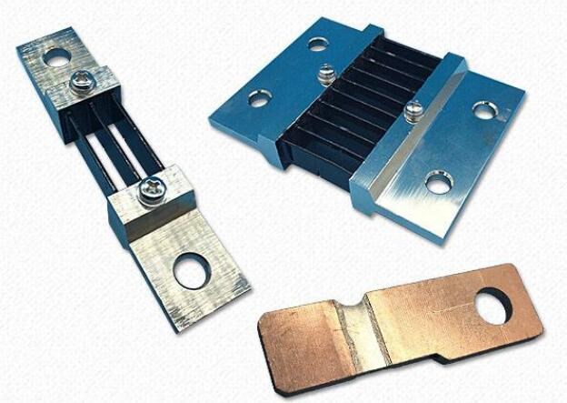
A shunt is a measuring element that uses voltage to indicate current. It is made according to the principle of generating voltage at both ends of the resistor when DC current passes through the resistor. It is connected in parallel with the current circuit of measuring instruments to expand its measurement range; or An element on which voltage is measured, thereby indirectly measuring current.
Read More
Subscribe to Utmel !
![MB2411JG01/UC-A-2A]() MB2411JG01/UC-A-2A
MB2411JG01/UC-A-2ANKK Switches
![YB15WCKG01-1CF02-JA]() YB15WCKG01-1CF02-JA
YB15WCKG01-1CF02-JANKK Switches
![MB2065LS1G01-BA]() MB2065LS1G01-BA
MB2065LS1G01-BANKK Switches
![UB216KKW016G-3JB]() UB216KKW016G-3JB
UB216KKW016G-3JBNKK Switches
![M2T19TXG13-DG]() M2T19TXG13-DG
M2T19TXG13-DGNKK Switches
![KP0215ASBKGG03RGB-2FJB]() KP0215ASBKGG03RGB-2FJB
KP0215ASBKGG03RGB-2FJBNKK Switches
![W22D20001-AZZ00-000]() W22D20001-AZZ00-000
W22D20001-AZZ00-000Carling Technologies
![BZE9-2RN2-C]() BZE9-2RN2-C
BZE9-2RN2-CHoneywell
![M2T19TXW13-DF]() M2T19TXW13-DF
M2T19TXW13-DFNKK Switches
![JWL12BAA-H]() JWL12BAA-H
JWL12BAA-HNKK Switches