Product
 Brand
Brand Articles
 Tools
Tools
How Does the A4988 Stepper Motor Driver Work

How to drive a stepper motor easily using A4988 and Arduino
Quick answer
The A4988 is a bipolar stepper-motor driver IC with two integrated DMOS full bridges, a microstepping translator, and fixed off-time PWM current regulation. A controller does not generate the motor phase sequence itself. It sets DIR, selects a step mode with MS1 through MS3, and sends a rising edge to STEP for each requested increment. The A4988 translator then selects the current magnitude and polarity for both motor windings.
The device supports full, half, quarter, eighth, and sixteenth steps. Allegro specifies an 8 V to 35 V motor-supply operating range, a 3 V to 5.5 V logic supply, and output capability up to +/-2 A. That 2 A figure is not a guarantee of continuous current on every carrier board: the current limit, PCB copper, exposed-pad connection, airflow, ambient temperature, and cooling determine the practical result.
What Is the A4988 Stepper Motor Driver?
The A4988 is a complete microstepping driver for two-phase bipolar stepper motors. It combines the translator, two current-regulated full bridges, gate drive, synchronous rectification, and protection functions in one 28-contact QFN package. The external controller therefore needs only a small number of logic signals instead of calculating and switching four bridge inputs for every phase-current state.
The IC appears in motion-control equipment and on many third-party carrier modules used in 3D printers, small CNC machines, positioning systems, and prototypes. A carrier module is not the same thing as the bare A4988. Module pinout, sense-resistor value, current-adjustment method, capacitor population, and thermal performance vary by board manufacturer.
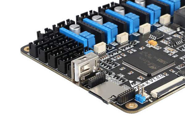
Original Utmel image retained. Motion-control boards often use plug-in driver carriers, but the carrier's current and cooling limits must be checked separately from the A4988 IC rating.
Key A4988 specifications
| Motor supply, VBB | 8 V to 35 V operating range |
|---|---|
| Logic supply, VDD | 3 V to 5.5 V operating range |
| Output capability | Up to +/-2 A device rating; practical continuous current is thermally limited |
| Motor type | Two-phase bipolar stepper motor |
| Step modes | Full, 1/2, 1/4, 1/8, and 1/16 step |
| Current regulation | Fixed off-time PWM with slow or mixed current decay |
| Package | 5 mm x 5 mm QFN with exposed thermal pad |
How Does the A4988 Work?
A bipolar stepper motor has two windings. Producing rotation requires controlled current in both windings, with the current magnitude and polarity changing in a defined sequence. The A4988's translator stores that sequence. Each rising edge at STEP advances the translator by one selected increment, while DIR determines which direction the sequence advances.
The translator drives two internal digital-to-analog converters. Their outputs establish the target current for the two phases at each microstep position. Two fixed off-time current regulators compare the winding-current sense signals with those targets and control the dual DMOS full bridges. The bridges then source or sink current through coil A and coil B.
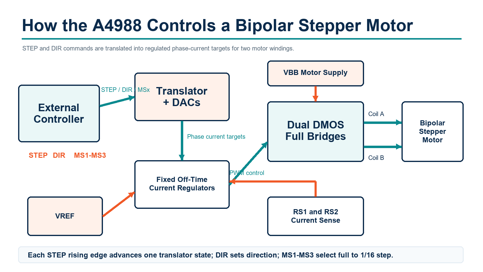
The external controller provides STEP, DIR, and MS1-MS3. The A4988 generates the phase-current targets and regulates the two motor windings.
What happens on one STEP pulse?
A low-to-high transition appears at STEP.
The translator advances one state in the direction selected by DIR.
The translator updates both DAC current targets and phase polarities.
The PWM current regulators compare the sense-resistor voltage with the target for each winding.
The full bridges switch the winding current and apply the selected decay behavior.
The A4988 does not contain a motion planner or a pulse generator for positioning. Acceleration, deceleration, target position, and STEP timing must come from the microcontroller, motion controller, or printer-control firmware.
STEP, DIR, and Microstep Selection
STEP and DIR are separate logic inputs. DIR is a level that selects sequence direction; it is not controlled by the polarity of the STEP pulse. A STEP rising edge advances one increment. Allegro specifies a minimum STEP high time of 1 us, a minimum STEP low time of 1 us, and 200 ns setup and hold times for DIR, RESET, and the microstep-selection inputs relative to the STEP edge.
| MS1 | MS2 | MS3 | Resolution |
|---|---|---|---|
| Low | Low | Low | Full step |
| High | Low | Low | Half step |
| Low | High | Low | Quarter step |
| High | High | Low | Eighth step |
| High | High | High | Sixteenth step |
MS1 and MS3 include 100 kohm pull-down resistances, while MS2 has a 50 kohm pull-down resistance. Leaving all three low selects full-step operation. A step-mode change takes effect on the next STEP rising edge. If absolute position must be preserved, change resolution at a translator state common to both modes or reset and re-home the motion system.
STEP frequency and motor speed
The commanded speed can be estimated from:
RPM = STEP frequency x 60 / (motor full steps per revolution x microsteps per full step)
For a 200-full-step motor at 1/16 step, 3,200 STEP pulses command one revolution. This is a command relationship, not proof of actual shaft speed. Excess acceleration, insufficient current, resonance, supply limits, or mechanical overload can cause missed steps.
How A4988 PWM Current Regulation Works
Stepper motors are normally controlled by winding current, not by simply applying their nameplate voltage. The A4988 repeatedly enables a bridge so the winding current rises. When the voltage across the external sense resistor reaches the DAC-controlled threshold, the PWM latch turns off the appropriate source driver for a fixed off-time. This chopping process regulates phase current while allowing a motor supply higher than the winding's low DC voltage rating, which helps current rise faster at speed.
Current-limit equation
For the bare IC, Allegro gives the maximum current-trip relationship as:
ITripMAX = VREF / (8 x RS)
For example, with a 0.10 ohm sense resistor and VREF of 0.80 V:
ITripMAX = 0.80 / (8 x 0.10) = 1.0 A
Do not copy a VREF value from another carrier board unless its sense-resistor value and reference circuit are the same. Some modules expose a potentiometer, while others use different resistor values or measurement points. Read the carrier documentation and measure carefully with the motor power removed when the board manufacturer requires that procedure.
Why the 2 A rating needs context
The +/-2 A number is a device rating, not a universal continuous operating recommendation. Conduction loss occurs in the source and sink MOSFETs, and the package must transfer that heat through its exposed pad into PCB copper. Small plug-in boards can reach thermal shutdown well below 2 A per phase unless their design, airflow, and cooling support the load. Validate case temperature, ambient temperature, current waveform, and fault behavior on the finished assembly.
Slow Decay and Mixed Decay
When the current regulator reaches its trip point, the bridge must provide a path for winding current during the off-time. The selected path determines how quickly the current decays.
Slow decay changes winding current gradually and can reduce ripple when the commanded current is rising or nearly constant.
Mixed decay begins with fast decay for 31.25% of the off-time and then changes to slow decay for the remainder.
In the standard automatic mode, the A4988 selects slow or mixed decay according to the translator's current transition. This helps reduce waveform distortion caused by motor back EMF. For low-current microstepping or unusual motors, the ROSC connection changes off-time and decay behavior; use the exact Allegro data-sheet options instead of treating mixed decay as a generic on/off feature.
A4988 Connection Checklist
The bare QFN device and a plug-in carrier have different pin layouts, so this checklist describes functions rather than a universal module pin order.
Confirm the two coil pairs. Connect one motor winding across OUT1A and OUT1B and the other across OUT2A and OUT2B. Incorrect pairing commonly produces vibration without rotation.
Connect the motor supply. VBB must remain within the 8 V to 35 V operating range and must have the local decoupling network shown for the selected board or IC layout.
Connect the logic supply. VDD must be between 3 V and 5.5 V. The controller and driver need a valid logic reference and ground arrangement.
Set RESET and SLEEP correctly. Both are active-low controls. RESET returns the translator to its Home state and turns off the FET outputs; SLEEP minimizes power consumption and disables operation.
Select the microstep mode. Set MS1, MS2, and MS3 before sending STEP pulses unless the motion sequence explicitly handles a mode change.
Set the current limit. Use VREF and the actual sense resistance. Do not infer current solely from motor-supply current.
Check timing and motion profile. Respect the logic timing limits and ramp STEP frequency so the motor can accelerate without losing synchronization.
Power down before rewiring. Avoid connecting or disconnecting motor windings on an energized carrier; follow the board manufacturer's power-sequencing instructions.
Protection Features and Their Limits
The A4988 includes thermal shutdown with hysteresis, VDD undervoltage lockout, crossover-current protection, short-to-ground protection, shorted-load protection, and overcurrent protection. Synchronous rectification reduces dissipation during PWM operation.
Protection is a last line of defense, not a substitute for correct design. Repeated thermal shutdown means the operating point or cooling is unsuitable. Overcurrent protection does not replace the programmed phase-current limit, and no internal feature can correct an incorrectly wired motor, inadequate supply decoupling, poor grounding, or excessive connector resistance.
Common A4988 Problems
The motor vibrates but does not rotate
First identify the two winding pairs with the motor documentation or a resistance measurement. Confirm that each pair is connected to one bridge. Then check STEP pulses, DIR setup time, current limit, and the acceleration profile.
The driver becomes very hot
Check the current-limit calculation, sense-resistor value, motor current rating, supply voltage, switching activity, PCB thermal path, and airflow. Do not assume a module can continuously deliver the IC's 2 A maximum rating.
The motor loses torque at speed
Possible causes include an acceleration ramp that is too aggressive, insufficient motor-supply voltage for the required current rise, an unsuitable current limit, excessive mechanical load, or resonance. Raising the voltage is not automatically safe; VBB and board limits still apply.
Microstepping is uneven or noisy
Verify the MS inputs, phase-current limit, motor wiring, supply decoupling, and decay configuration. At very low current, minimum on-time can prevent ideal regulation at the smallest microstep current levels. Allegro documents a ROSC configuration for low-current microstepping.
The driver does not respond to STEP
Confirm VDD, VBB, common ground, SLEEP, RESET, ENABLE state on the specific board, and the STEP waveform. After reset, thermal shutdown, or an overcurrent event, the translator returns to its Home position.
Frequently Asked Questions
Can an A4988 drive a unipolar stepper motor?
The A4988 is designed for bipolar two-phase operation. Some six-wire or eight-wire motors can be connected as bipolar motors if their winding configuration and ratings are understood. A five-wire unipolar motor with a common internal connection is generally not suitable without internal rewiring.
Does microstepping increase torque?
Microstepping improves commanded position resolution and can reduce vibration, but it does not multiply available motor torque. Incremental torque per microstep is lower than full-step holding torque, and load, current, speed, and mechanics still determine usable motion.
Is 12 V safe for every A4988 motor?
The A4988 motor-supply range includes 12 V, but the motor must be protected by a correctly set phase-current limit. The carrier's voltage rating, decoupling, and transient behavior also matter. Motor winding voltage alone is not the correct basis for selecting the supply.
How many STEP pulses make one revolution?
Multiply the motor's full steps per revolution by the selected microsteps per full step. A 200-step motor in 1/16-step mode requires 3,200 commanded pulses per revolution, assuming no missed steps and no gearbox.
Can I change microstep mode while the motor is moving?
The inputs can be changed, and the new mode takes effect on the next STEP rising edge. However, changing at a translator position that is not shared by both modes can shift the commanded phase state. Plan the transition or stop and re-home if absolute position matters.
Conclusion
The A4988 simplifies bipolar stepper control by translating STEP and DIR commands into regulated two-phase current waveforms. Reliable operation depends on more than sending pulses: the designer must set the correct current limit, identify the winding pairs, respect logic timing, select an appropriate motor supply, manage heat, and follow the exact carrier or bare-IC layout requirements.
The most important correction to the common simplified explanation is that STEP pulses come from an external controller. Inside the A4988, the translator, DACs, fixed off-time current regulators, and dual full bridges turn those commands into controlled winding current.
Engineering References
 UTMEL
UTMEL
We are the professional distributor of electronic components, providing a large variety of products to save you a lot of time, effort, and cost with our efficient self-customized service. careful order preparation fast delivery service
 UTMEL 2024 Annual gala: Igniting Passion, Renewing BrillianceUTMEL18 January 20245087
As the year comes to an end and the warm sun rises, Utmel Electronics celebrates its 6th anniversary.
Read More Electronic Components Distributor Utmel to Showcase at 2024 IPC APEX EXPOUTMEL10 April 20246096
Utmel, a leading electronic components distributor, is set to make its appearance at the 2024 IPC APEX EXPO.
Read More UTMEL Showcases One-Stop Electronic Component Sourcing Services at electronica Shanghai 2026UTMEL07 July 2026402
SHANGHAI, China, July 7, 2026 - UTMEL, a one-stop electronic components sourcing platform operated by Shenzhen Utmel Intelligent Electronic Co., Ltd., successfully participated in electronica Shanghai 2026, held from July 1 to 3, 2026 at the Shanghai New International Expo Centre.
Read More Electronic components distributor UTMEL to Showcase at electronica ChinaUTMEL07 June 20244672
The three-day 2024 Electronica China will be held at the Shanghai New International Expo Center from July 8th to 10th, 2024.
Read More Electronic components distributor UTMEL Stands Out at electronica china 2024UTMEL09 July 20245273
From July 8th to 10th, the three-day electronica china 2024 kicked off grandly at the Shanghai New International Expo Center.
Read More
Subscribe to Utmel !
![72XWR50LF]() 72XWR50LF
72XWR50LFTT Electronics
![3224W-ZTE-102E]() 3224W-ZTE-102E
3224W-ZTE-102EBourns
![3224W-ZTE-201E]() 3224W-ZTE-201E
3224W-ZTE-201EBourns
![3224W-ZTE-104E]() 3224W-ZTE-104E
3224W-ZTE-104EBourns
![3296W-IND-102LF]() 3296W-IND-102LF
3296W-IND-102LFBourns
![3296X-ZTE-202LF]() 3296X-ZTE-202LF
3296X-ZTE-202LFBourns
![3296W-KRN-502LF]() 3296W-KRN-502LF
3296W-KRN-502LFBourns
![3296W-KRN-203LF]() 3296W-KRN-203LF
3296W-KRN-203LFBourns
![3296W-IND-200LF]() 3296W-IND-200LF
3296W-IND-200LFBourns
![38WLAAR5KLF30]() 38WLAAR5KLF30
38WLAAR5KLF30BI Technologies