
PCA9685 LED Controller: Datasheet, PCA9685 Arduino, Schematic

2.5/5V 0.65mm PMIC PCA9685 100kHz~1MHz 3V 28-TSSOP (0.173, 4.40mm Width)
Unit Price: $1.941283
Ext Price: $1.94


2.5/5V 0.65mm PMIC PCA9685 100kHz~1MHz 3V 28-TSSOP (0.173, 4.40mm Width)
The PCA9685 is an I2C-bus controlled 16-channel LED controller. This post will unlock more details about PCA9685. There is a huge range of Semiconductors, Capacitors, Resistors and ICs in stock. Welcome RFQ!
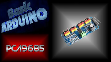
How to setup and use a PCA9685 with your Arduino to control up to 16 servos.
PCA9685 Pinout

PCA9685 Pinout
Pin No. | Pin Name | Pin Configuration |
1 | A0 | address input 0 |
2 | A1 | address input 1 |
3 | A2 | address input 2 |
4 | A3 | address input 3 |
5 | A4 | address input 4 |
6 | LED0 | LED driver 0 |
7 | LED1 | LED driver 1 |
8 | LED2 | LED driver 2 |
9 | LED3 | LED driver 3 |
10 | LED4 | LED driver 4 |
11 | LED5 | LED driver 5 |
12 | LED6 | LED driver 6 |
13 | LED7 | LED driver 7 |
14 | Vss | Supply Ground |
15 | LED8 | LED driver |
16 | LED9 | LED driver 9 |
17 | LED10 | LED driver 10 |
18 | LED11 | LED driver 11 |
19 | LED12 | LED driver 12 |
20 | LED13 | LED driver 13 |
21 | LED14 | LED driver 14 |
22 | LED15 | LED driver 15 |
23 | OE | active LOW output enable |
24 | A5 | address input 5 |
25 | EXTCLK | external clock input |
26 | SCL | serial clock line |
27 | SDA | serial data line |
28 | VDD | supply voltage |
PCA9685 CAD Model
Symbol

PCA9685 Symbol
Footprint

PCA9685 Footprint
CAD Model

PCA9685 3D Model
PCA9685 Description
The PCA9685 is an I2C-bus controlled 16-channel LED controller optimized for Red/Green/Blue/Amber (RGBA) colour backlighting applications. Each LED output has its own 12-bit resolution (4096 steps) fixed frequency individual PWM controller that operates at a programmable frequency from a typical of 24 Hz to 1526 Hz with a duty cycle that is adjustable from 0 % to 100 % to allow the LED to be set to a specific brightness value. All outputs are set to the same PWM frequency.
Each LED output can be off or on (no PWM control) or set at its individual PWM controller value. The LED output driver is programmed to be either open-drain with a 25 mA current sink capability at 5 V or a totem pole with a 25 mA sink, 10 mA source capability at 5 V.
ThePCA9685 operates with a supply voltage range of 2.3 V to 5.5 V and the inputs and outputs are 5.5 V tolerant. LEDs can be directly connected to the LED output (up to 25 mA, 5.5 V) or controlled with external drivers and a minimum amount of discrete components for larger current or higher voltage LEDs. The PCA9685 is in the new Fast-mode Plus (Fm+) family. Fm+ devices offer higher frequency (up to 1 MHz) and more densely populated bus operation (up to 4000 pF).
PCA9685 Feature
16 LED drivers. Each output is programmable at:
Off
On
Programmable LED brightness
Programmable LED turn-on time to help reduce EMI
1 MHz Fast-mode Plus compatible I2C-bus interface with 30 mA high drive capability on SDA output for driving high capacitive buses
4096-step (12-bit) linear programmable brightness per LED output varying from fully off (default) to maximum brightness
LED output frequency (all LEDs) typically varies from 24 Hz to 1526 Hz (Default of 1Eh in PRE_SCALE register results in a 200 Hz refresh rate with oscillator clock of 25 MHz.)
Sixteen totem pole outputs (sink 25 mA and source 10 mA at 5 V) with software-programmable open-drain LED outputs selection (default at totem pole). No input function.
Output state change programmable on the Acknowledge or the STOP Command to update outputs byte-by-byte or all at the same time (default to ‘Change on STOP’).
Active LOW Output Enable (OE) input pin. LEDs output programmable to logic 1, logic 0 (default at power-up) or ‘high-impedance’ when OE is HIGH.
6 hardware address pins allow 62 PCA9685 devices to be connected to the same I 2C-bus
Toggling OE allows for hardware LED blinking
4 software-programmable I2C-bus addresses (one LED All Call address and three LED Sub Call addresses) allow groups of devices to be addressed at the same time in any combination (for example, one register used for all Call's that all the PCA9685s on the I2C-bus can be addressed at the same time and the second register used for three different addresses so that 1⁄ 3 of all devices on the bus can be addressed at the same time in a group). The software enables and disables these I2C-bus addresses.
Software Reset feature (SWRST General Call) allows the device to be reset through the I2C-bus
25 MHz typical internal oscillator requires no external components
External 50 MHz (max.) clock input
Internal power-on reset
Noise filter on SDA/SCL inputs
Edge rate control on outputs
No output glitches on power-up
Supports hot insertion
Low standby current
Operating power supply voltage range of 2.3 V to 5.5 V
5.5 V tolerant inputs
-40 ℃ to +85 ℃ operation
ESD protection exceeds 2000 V HBM per JESD22-A114, 200 V MM per JESD22-A115 and 1000 V CDM per JESD22-C101
Latch-up testing is done to JEDEC Standard JESD78 which exceeds 100 mA
Packages offered: TSSOP28, HVQFN28
PCA9685 Application
RGB or RGBA LED drivers
LED status information
LED displays
LCD backlights
Keypad backlights for cellular phones or handheld devices
PCA9685 Equivalent
The equivalent for PCA9685:
TLC5971
LED6001
MAX16803
RT9288A
How to Use PCA9685?
The PCA9685 is easy to use because it communicates with other devices via an I2C bus. A block diagram of PCA9685 is shown below for reference.

PCA9685 Block Diagram
As you can see in the diagram above, you have your SCL and SDA lines for communication, which require two pullup resistors because the device lacks internal pullup resistors. You also have your A0 to A5 address lines, which are used to configure the device's I2C address. The device also has the choice of operating with an external clock or an internal clock.
PCA9685 Application Schematic

PCA9685 Application Schematic
Parts with Similar Specs
- ImagePart NumberManufacturerPackage / CaseNumber of OutputsRoHS StatusInternal Switch(s)HTS CodeNumber of SegmentsOperating TemperatureMultiplexed Display CapabilityView Compare
![PCA9685PW,118]()
PCA9685PW,118
28-TSSOP (0.173, 4.40mm Width)
16
ROHS3 Compliant
Yes
8542.39.00.01
16
-40°C ~ 85°C (TA)
NO
![TLC59116IPWR]()
24-TSSOP (0.173, 4.40mm Width)
16
ROHS3 Compliant
Yes
8542.39.00.01
16
-40°C ~ 85°C (TA)
NO
![TLC59116FIPWR]()
28-TSSOP (0.173, 4.40mm Width)
16
ROHS3 Compliant
Yes
8542.39.00.01
16
-40°C ~ 85°C (TA)
NO
![CAT4016Y-T2]()
28-TSSOP (0.173, 4.40mm Width)
16
ROHS3 Compliant
Yes
8542.39.00.01
16
-40°C ~ 85°C (TA)
NO
![TLC5946PW]()
28-TSSOP (0.173, 4.40mm Width)
16
ROHS3 Compliant
Yes
8542.39.00.01
16
-40°C ~ 85°C (TA)
NO


Specifications
- TypeParameter
- Factory Lead Time7 Weeks
- Mounting Type
The "Mounting Type" in electronic components refers to the method used to attach or connect a component to a circuit board or other substrate, such as through-hole, surface-mount, or panel mount.
Surface Mount - Package / Case
refers to the protective housing that encases an electronic component, providing mechanical support, electrical connections, and thermal management.
28-TSSOP (0.173, 4.40mm Width) - Surface Mount
having leads that are designed to be soldered on the side of a circuit board that the body of the component is mounted on.
YES - Operating Temperature
The operating temperature is the range of ambient temperature within which a power supply, or any other electrical equipment, operate in. This ranges from a minimum operating temperature, to a peak or maximum operating temperature, outside which, the power supply may fail.
-40°C~85°C TA - Packaging
Semiconductor package is a carrier / shell used to contain and cover one or more semiconductor components or integrated circuits. The material of the shell can be metal, plastic, glass or ceramic.
Tape & Reel (TR) - Published2003
- JESD-609 Code
The "JESD-609 Code" in electronic components refers to a standardized marking code that indicates the lead-free solder composition and finish of electronic components for compliance with environmental regulations.
e4 - Part Status
Parts can have many statuses as they progress through the configuration, analysis, review, and approval stages.
Active - Moisture Sensitivity Level (MSL)
Moisture Sensitivity Level (MSL) is a standardized rating that indicates the susceptibility of electronic components, particularly semiconductors, to moisture-induced damage during storage and the soldering process, defining the allowable exposure time to ambient conditions before they require special handling or baking to prevent failures
1 (Unlimited) - Number of Terminations28
- TypeLinear
- Terminal Finish
Terminal Finish refers to the surface treatment applied to the terminals or leads of electronic components to enhance their performance and longevity. It can improve solderability, corrosion resistance, and overall reliability of the connection in electronic assemblies. Common finishes include nickel, gold, and tin, each possessing distinct properties suitable for various applications. The choice of terminal finish can significantly impact the durability and effectiveness of electronic devices.
NICKEL PALLADIUM GOLD - Applications
The parameter "Applications" in electronic components refers to the specific uses or functions for which a component is designed. It encompasses various fields such as consumer electronics, industrial automation, telecommunications, automotive, and medical devices. Understanding the applications helps in selecting the right components for a particular design based on performance, reliability, and compatibility requirements. This parameter also guides manufacturers in targeting their products to relevant markets and customer needs.
Backlight - HTS Code
HTS (Harmonized Tariff Schedule) codes are product classification codes between 8-1 digits. The first six digits are an HS code, and the countries of import assign the subsequent digits to provide additional classification. U.S. HTS codes are 1 digits and are administered by the U.S. International Trade Commission.
8542.39.00.01 - Terminal Position
In electronic components, the term "Terminal Position" refers to the physical location of the connection points on the component where external electrical connections can be made. These connection points, known as terminals, are typically used to attach wires, leads, or other components to the main body of the electronic component. The terminal position is important for ensuring proper connectivity and functionality of the component within a circuit. It is often specified in technical datasheets or component specifications to help designers and engineers understand how to properly integrate the component into their circuit designs.
DUAL - Terminal Form
Occurring at or forming the end of a series, succession, or the like; closing; concluding.
GULL WING - Peak Reflow Temperature (Cel)
Peak Reflow Temperature (Cel) is a parameter that specifies the maximum temperature at which an electronic component can be exposed during the reflow soldering process. Reflow soldering is a common method used to attach electronic components to a circuit board. The Peak Reflow Temperature is crucial because it ensures that the component is not damaged or degraded during the soldering process. Exceeding the specified Peak Reflow Temperature can lead to issues such as component failure, reduced performance, or even permanent damage to the component. It is important for manufacturers and assemblers to adhere to the recommended Peak Reflow Temperature to ensure the reliability and functionality of the electronic components.
260 - Number of Functions1
- Supply Voltage
Supply voltage refers to the electrical potential difference provided to an electronic component or circuit. It is crucial for the proper operation of devices, as it powers their functions and determines performance characteristics. The supply voltage must be within specified limits to ensure reliability and prevent damage to components. Different electronic devices have specific supply voltage requirements, which can vary widely depending on their design and intended application.
3V - Terminal Pitch
The center distance from one pole to the next.
0.65mm - Frequency
In electronic components, the parameter "Frequency" refers to the rate at which a signal oscillates or cycles within a given period of time. It is typically measured in Hertz (Hz) and represents how many times a signal completes a full cycle in one second. Frequency is a crucial aspect in electronic components as it determines the behavior and performance of various devices such as oscillators, filters, and communication systems. Understanding the frequency characteristics of components is essential for designing and analyzing electronic circuits to ensure proper functionality and compatibility with other components in a system.
100kHz~1MHz - Time@Peak Reflow Temperature-Max (s)
Time@Peak Reflow Temperature-Max (s) refers to the maximum duration that an electronic component can be exposed to the peak reflow temperature during the soldering process, which is crucial for ensuring reliable solder joint formation without damaging the component.
30 - Base Part Number
The "Base Part Number" (BPN) in electronic components serves a similar purpose to the "Base Product Number." It refers to the primary identifier for a component that captures the essential characteristics shared by a group of similar components. The BPN provides a fundamental way to reference a family or series of components without specifying all the variations and specific details.
PCA9685 - Pin Count
a count of all of the component leads (or pins)
28 - JESD-30 Code
JESD-30 Code refers to a standardized descriptive designation system established by JEDEC for semiconductor-device packages. This system provides a systematic method for generating designators that convey essential information about the package's physical characteristics, such as size and shape, which aids in component identification and selection. By using JESD-30 codes, manufacturers and engineers can ensure consistency and clarity in the specification of semiconductor packages across various applications and industries.
R-PDSO-G28 - Number of Outputs16
- Qualification Status
An indicator of formal certification of qualifications.
Not Qualified - Power Supplies
an electronic circuit that converts the voltage of an alternating current (AC) into a direct current (DC) voltage.?
2.5/5V - Internal Switch(s)
The term "Internal Switch(s)" in electronic components typically refers to a built-in mechanism within a device that allows for the control of electrical current flow. These internal switches can be used to turn circuits on or off, change the direction of current, or regulate the flow of electricity within the component. They are often designed to be controlled externally, either manually or automatically, to enable various functions or operations within the electronic device. Internal switches play a crucial role in the overall functionality and performance of electronic components by providing a means to manage and manipulate electrical signals effectively.
Yes - fmax-Min
fmax-Min refers to the frequency range that an electronic component or system can operate within. It represents the difference between the maximum frequency (fmax) and the minimum frequency (Min) limits of operation. This parameter is crucial in defining the bandwidth of the component, indicating how effectively it can transmit or receive signals over that range. A wider fmax-Min value typically signifies better performance for applications that require broad frequency response.
1 MHz - Dimming
Dimming is a feature in electronic components, such as LED lights or display screens, that allows the user to adjust the brightness level of the device. It is a method of controlling the amount of light output by the component, typically by varying the voltage or current supplied to it. Dimming can be achieved through various techniques, such as pulse-width modulation (PWM) or analog dimming. This feature is commonly used to save energy, create ambiance, or enhance visual comfort in different applications.
PWM - Number of Segments16
- Voltage - Supply (Max)
Voltage - Supply (Max) is a parameter in electronic components that specifies the maximum voltage that can be safely applied to the component for proper operation. This parameter is crucial for ensuring the component's longevity and preventing damage due to overvoltage conditions. Exceeding the maximum supply voltage can lead to component failure, reduced performance, or even permanent damage. Designers must carefully consider this parameter when selecting components and designing circuits to ensure reliable and safe operation within the specified voltage limits.
5.5V - Voltage - Supply (Min)
Voltage - Supply (Min) is a parameter in electronic components that specifies the minimum voltage required for the component to operate within its specified performance range. This parameter indicates the lowest voltage level that can be safely applied to the component without causing malfunctions or damage. It is crucial to ensure that the supply voltage provided to the component is equal to or higher than the specified minimum voltage to guarantee proper functionality and reliability. Failure to meet this requirement may result in erratic behavior, reduced performance, or even permanent damage to the component.
2.3V - Multiplexed Display Capability
Multiplexed Display Capability refers to the ability of an electronic component or system to control multiple display elements using fewer input/output lines. This is achieved by rapidly switching between different displays or segments, allowing for efficient communication and reduced wiring complexity. In multiplexed systems, each display is activated sequentially, creating the illusion of simultaneous display to the user. This capability is commonly utilized in devices like LED matrices and LCD screens to enhance functionality while conserving space and resources.
NO - Data Input Mode
Data Input Mode in electronic components refers to the specific method or protocol used to input data into the component. This parameter determines how data is received and processed by the component, whether it be through serial communication, parallel communication, or other interfaces. The data input mode is crucial for ensuring compatibility and proper functioning of the component within a larger electronic system. Understanding and configuring the data input mode correctly is essential for effective data transfer and communication between different components in a circuit or system.
SERIAL - Length9.7mm
- Height Seated (Max)
Height Seated (Max) is a parameter in electronic components that refers to the maximum allowable height of the component when it is properly seated or installed on a circuit board or within an enclosure. This specification is crucial for ensuring proper fit and alignment within the overall system design. Exceeding the maximum seated height can lead to mechanical interference, electrical shorts, or other issues that may impact the performance and reliability of the electronic device. Manufacturers provide this information to help designers and engineers select components that will fit within the designated space and function correctly in the intended application.
1.1mm - Width4.4mm
- RoHS Status
RoHS means “Restriction of Certain Hazardous Substances” in the “Hazardous Substances Directive” in electrical and electronic equipment.
ROHS3 Compliant
PCA9685 Package

PCA9685 Package
PCA9685 Manufacturer
NXP Semiconductors enables secure connections and infrastructure for a smarter world, advancing solutions that make lives easier, better and safer. As the world leader in secure connectivity solutions for embedded applications, NXP is driving innovation in the secure connected vehicle, end-to-end security & privacy and smart connected solutions markets. Built on more than 60 years of combined experience and expertise, the company has 45,000 employees in more than 35 countries. Freescale Semiconductor has been acquired by NXP Semiconductor. Freescale Semiconductor parts are now a part of the NXP family (Dec 2015).
Datasheet PDF
- Datasheets :
- Environmental Information :
Trend Analysis
What is a PCA9685?
The PCA9685 is an I2C-bus controlled 16-channel LED controller optimized for Red/Green/Blue/Amber (RGBA) colour backlighting applications. Each LED output has its own 12-bit resolution (4096 steps) fixed frequency individual PWM controller that operates at a programmable frequency from a typical of 24 Hz to 1526 Hz with a duty cycle that is adjustable from 0 % to 100 % to allow the LED to be set to a specific brightness value. All outputs are set to the same PWM frequency.
What is the output voltage of the pca9685 led driver?
The LED output driver is programmed to be either open-drain with a 25 mA current sink capability at 5 V or totem pole with a 25 mA sink, 10 mA source capability at 5 V. The PCA9685 operates with a supply voltage range of 2.3 V to 5.5 V and the inputs and outputs are 5.5 V tolerant.
How many servos can I control with a pca9685 servo driver?
This post shows you how to use a PCA9685 Servo Driver module to control up to 16 servos with your Arduino board. PCA9685 is a 16-Channel, 12-Bit PWM Servo Driver that comes in handy when the MCU in your project doesn't have enough PWM output pins.
What is the power-on reset (POR) button on the pca9685?
The Power-On Reset (POR) default state of LEDs output pins is LOW in the case of PCA9685. It is HIGH for PCA9635 The active LOW Output Enable Input pin ( OE) allows asynchronous control of the LED outputs and can be used to set all the outputs to a defined I²C-bus programmable logic state.
How add adafruit library to Arduino?
Navigate to the Manage Libraries. option in the Sketch -> Includes Library menu. Enter Adafruit IO Arduino into the search box, and click Install on the Adafruit IO Arduino library option to install version 3.2.
 STM32F767ZIT6 Microcontroller: Pinout, Applications and Datasheet
17 November 20232662
 AD9516-4 Clock Generator: Pinout, Equivalent and Datasheet
09 April 2022276
 TPS22965NQWDSGRQ1 On-Resistance Load Switch: Circuit, Pinout, and Datasheet
08 April 2022756
 SX1276 Transceiver: Datasheet, SX1276 vs. SX1272
09 November 20216744
 STM32F303VCT6TR Microcontroller: 72MHz,100-LQFP, Pinout and Features
22 January 2022833
 W25Q64JVSSIQ: Overview, Features, and Datasheet
25 October 20231902
 MCP1825 Regulators, 500 mA Low Quiescent Current LDO Regulator and Datasheet pdf
28 December 20211324
 XMOS xCORE Multicore Microcontroller XE216-512-TQ128 Datasheet
29 February 202481
 What is Regulated Power Supply?
08 January 202113958
 Revolutionizing DC Link Bus Design: Unleashing High Frequency, High-Temperature Converter Potential
11 July 20232571
 Best Practices for Panel Meter Maintenance
11 July 2025410
 Tough Times for Japanese Component Manufacturers
10 August 20221365
 What is an LDO (Low Dropout Regulator)?
29 October 20214876
 What are the Commonly Used Circuit Protection Components?
04 May 20225065
 Chiplet Brings Change to the Business Model of IP Design Companies
05 September 20222525
 What is Conductivity Sensor?
20 June 202210632
NXP USA Inc.
In Stock: 7125
Minimum: 1 Multiples: 1
Qty
Unit Price
Ext Price
1
$1.941283
$1.94
10
$1.831399
$18.31
100
$1.727735
$172.77
500
$1.629938
$814.97
1000
$1.537678
$1,537.68
Not the price you want? Send RFQ Now and we'll contact you ASAP.
Inquire for More Quantity
![PCA9956BTWY]() PCA9956BTWY
PCA9956BTWYNXP USA Inc.
![PCA9622DR,118]() PCA9622DR,118
PCA9622DR,118NXP USA Inc.
![PCA9626B,118]() PCA9626B,118
PCA9626B,118NXP USA Inc.
![PCA9532BS,118]() PCA9532BS,118
PCA9532BS,118NXP USA Inc.
![PCA9624PW,118]() PCA9624PW,118
PCA9624PW,118NXP USA Inc.
![PCA9635PW,118]() PCA9635PW,118
PCA9635PW,118NXP USA Inc.
![PCA9635PW/Q900,118]() PCA9635PW/Q900,118
PCA9635PW/Q900,118NXP USA Inc.
![PCA9624BS,118]() PCA9624BS,118
PCA9624BS,118NXP USA Inc.
![PCA9532D,118]() PCA9532D,118
PCA9532D,118NXP USA Inc.


