
 Product
 Brand
Brand Articles
 Tools
Tools
ZiLOG ZLP12840 OTP MCU: Product Overview
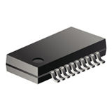


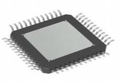
Microcontroller 20 Pin 2.5V SSOP
This technical article provides a detailed overview of the ZiLOG ZLP12840 OTP (One-Time Programmable) microcontroller, highlighting its key features, applications, pin-outs, ordering information, and support tools. Engineers and developers aiming to understand the capabilities and potential applications of this microcontroller will find valuable insights in this article.
Product Introduction
1. Description
The ZiLOG ZLP12840 OTP MCU is a member of the Crimzon™ MCU family of infrared microcontrollers. It is equipped with a Z8 LXM core, OTP ROM options ranging from 32K to 128K, and 1KB of general-purpose RAM. This microcontroller offers efficient memory usage, advanced interrupts, input/output capabilities, and automated pulse generation and reception. Additionally, it features flexible stop-mode recovery (SMR) and compatibility with other ZiLOG product families.
2. Features
The ZLP12840 OTP MCU boasts low power consumption with three standby modes, including STOP, HALT, and low voltage. It comes with infrared dedicated timers, up to 24 GPIO, and three peripherals from UART Tx Rx BRG. The microcontroller provides 20 priority interrupt sources and integrated power-on reset circuits. Notably, it is designed to offer efficient memory usage and sophisticated interrupts, making it suitable for diverse applications.
3. Applications
The ZLP12840 OTP MCU finds application in various domains, including infrared remote control systems, automated pulse generation and reception, and systems requiring efficient memory usage and advanced interrupt capabilities. Its capabilities make it suitable for applications demanding precise timing and response in infrared communication and control systems.
4. FAQs
- What are the key power-saving modes supported by the ZLP12840 OTP MCU?
The ZLP12840 OTP MCU supports three standby modes, including STOP mode consuming 2μA (typical), HALT mode consuming 0.8mA (typical), and low voltage mode.
- Are there any specific tools available for programming and debugging the ZLP12840 OTP MCU?
Yes, ZLP128ICE01ZEM Crimzon™ In-Circuit Emulator and ZiLOG Developer Studio II (ZDSII) are available to support programming and debugging of the ZLP12840 OTP MCU.
This technical article provides an encompassing understanding of the ZiLOG ZLP12840 OTP MCU, offering insights into its features, applications, pin-outs, ordering information, and support tools.
For a comprehensive technical guide, please refer to the complete product brief.
Specifications
- TypeParameter
- Package / Case
refers to the protective housing that encases an electronic component, providing mechanical support, electrical connections, and thermal management.
SSOP - Surface Mount
having leads that are designed to be soldered on the side of a circuit board that the body of the component is mounted on.
YES - Number of Pins20
- Frequency(Max)8MHz
- Memory TypesEPROM
- Number of I/Os16
- Watchdog TimersYes
- Published2004
- JESD-609 Code
The "JESD-609 Code" in electronic components refers to a standardized marking code that indicates the lead-free solder composition and finish of electronic components for compliance with environmental regulations.
e3 - Number of Terminations20
- Terminal Finish
Terminal Finish refers to the surface treatment applied to the terminals or leads of electronic components to enhance their performance and longevity. It can improve solderability, corrosion resistance, and overall reliability of the connection in electronic assemblies. Common finishes include nickel, gold, and tin, each possessing distinct properties suitable for various applications. The choice of terminal finish can significantly impact the durability and effectiveness of electronic devices.
Matte Tin (Sn) - Max Operating Temperature
The Maximum Operating Temperature is the maximum body temperature at which the thermistor is designed to operate for extended periods of time with acceptable stability of its electrical characteristics.
70°C - Min Operating Temperature
The "Min Operating Temperature" parameter in electronic components refers to the lowest temperature at which the component is designed to operate effectively and reliably. This parameter is crucial for ensuring the proper functioning and longevity of the component, as operating below this temperature may lead to performance issues or even damage. Manufacturers specify the minimum operating temperature to provide guidance to users on the environmental conditions in which the component can safely operate. It is important to adhere to this parameter to prevent malfunctions and ensure the overall reliability of the electronic system.
0°C - Terminal Position
In electronic components, the term "Terminal Position" refers to the physical location of the connection points on the component where external electrical connections can be made. These connection points, known as terminals, are typically used to attach wires, leads, or other components to the main body of the electronic component. The terminal position is important for ensuring proper connectivity and functionality of the component within a circuit. It is often specified in technical datasheets or component specifications to help designers and engineers understand how to properly integrate the component into their circuit designs.
DUAL - Terminal Form
Occurring at or forming the end of a series, succession, or the like; closing; concluding.
GULL WING - Peak Reflow Temperature (Cel)
Peak Reflow Temperature (Cel) is a parameter that specifies the maximum temperature at which an electronic component can be exposed during the reflow soldering process. Reflow soldering is a common method used to attach electronic components to a circuit board. The Peak Reflow Temperature is crucial because it ensures that the component is not damaged or degraded during the soldering process. Exceeding the specified Peak Reflow Temperature can lead to issues such as component failure, reduced performance, or even permanent damage to the component. It is important for manufacturers and assemblers to adhere to the recommended Peak Reflow Temperature to ensure the reliability and functionality of the electronic components.
260 - Supply Voltage
Supply voltage refers to the electrical potential difference provided to an electronic component or circuit. It is crucial for the proper operation of devices, as it powers their functions and determines performance characteristics. The supply voltage must be within specified limits to ensure reliability and prevent damage to components. Different electronic devices have specific supply voltage requirements, which can vary widely depending on their design and intended application.
2.5V - Terminal Pitch
The center distance from one pole to the next.
0.65mm - Time@Peak Reflow Temperature-Max (s)
Time@Peak Reflow Temperature-Max (s) refers to the maximum duration that an electronic component can be exposed to the peak reflow temperature during the soldering process, which is crucial for ensuring reliable solder joint formation without damaging the component.
40 - Pin Count
a count of all of the component leads (or pins)
20 - Supply Voltage-Max (Vsup)
The parameter "Supply Voltage-Max (Vsup)" in electronic components refers to the maximum voltage that can be safely applied to the component without causing damage. It is an important specification to consider when designing or using electronic circuits to ensure the component operates within its safe operating limits. Exceeding the maximum supply voltage can lead to overheating, component failure, or even permanent damage. It is crucial to adhere to the specified maximum supply voltage to ensure the reliable and safe operation of the electronic component.
3.6V - Temperature Grade
Temperature grades represent a tire's resistance to heat and its ability to dissipate heat when tested under controlled laboratory test conditions.
COMMERCIAL - Supply Voltage-Min (Vsup)
The parameter "Supply Voltage-Min (Vsup)" in electronic components refers to the minimum voltage level required for the component to operate within its specified performance range. This parameter indicates the lowest voltage that can be safely applied to the component without risking damage or malfunction. It is crucial to ensure that the supply voltage provided to the component meets or exceeds this minimum value to ensure proper functionality and reliability. Failure to adhere to the specified minimum supply voltage may result in erratic behavior, reduced performance, or even permanent damage to the component.
2V - Interface
In electronic components, the term "Interface" refers to the point at which two different systems, devices, or components connect and interact with each other. It can involve physical connections such as ports, connectors, or cables, as well as communication protocols and standards that facilitate the exchange of data or signals between the connected entities. The interface serves as a bridge that enables seamless communication and interoperability between different parts of a system or between different systems altogether. Designing a reliable and efficient interface is crucial in ensuring proper functionality and performance of electronic components and systems.
UART - Memory Size
The memory capacity is the amount of data a device can store at any given time in its memory.
96kB - RAM Size
RAM size refers to the amount of random access memory (RAM) available in an electronic component, such as a computer or smartphone. RAM is a type of volatile memory that stores data and instructions that are actively being used by the device's processor. The RAM size is typically measured in gigabytes (GB) and determines how much data the device can store and access quickly for processing. A larger RAM size allows for smoother multitasking, faster loading times, and better overall performance of the electronic component. It is an important factor to consider when choosing a device, especially for tasks that require a lot of memory, such as gaming, video editing, or running multiple applications simultaneously.
1004B - uPs/uCs/Peripheral ICs Type
The parameter "uPs/uCs/Peripheral ICs Type" refers to the classification of various integrated circuits used in electronic devices. It encompasses microprocessors (uPs), microcontrollers (uCs), and peripheral integrated circuits that provide additional functionalities. This classification helps in identifying the specific type of chip used for processing tasks, controlling hardware, or interfacing with other components in a system. Understanding this parameter is essential for selecting the appropriate electronic components for a given application.
MICROCONTROLLER - Bit Size
In electronic components, "Bit Size" refers to the number of bits that can be processed or stored by a particular component. A bit is the smallest unit of data in computing and can have a value of either 0 or 1. The Bit Size parameter is commonly used to describe the capacity or performance of components such as microprocessors, memory modules, and data buses. A larger Bit Size generally indicates a higher processing capability or storage capacity, allowing for more complex operations and larger amounts of data to be handled efficiently. It is an important specification to consider when selecting electronic components for specific applications that require certain levels of performance and data processing capabilities.
8 - Access Time
Access time in electronic components refers to the amount of time it takes for a system to retrieve data from memory or storage once a request has been made. It is typically measured in nanoseconds or microseconds and indicates the speed at which data can be accessed. Lower access time values signify faster performance, allowing for more efficient processing in computing systems. Access time is a critical parameter in determining the overall responsiveness of electronic devices, particularly in applications requiring quick data retrieval.
8 μs - Has ADC
Has ADC refers to the presence of an Analog-to-Digital Converter (ADC) in an electronic component. An ADC is a crucial component in many electronic devices as it converts analog signals, such as voltage or current, into digital data that can be processed by a digital system. Having an ADC allows the electronic component to interface with analog signals and convert them into a format that can be manipulated and analyzed digitally. This parameter is important for applications where analog signals need to be converted into digital form for further processing or control.
NO - DMA Channels
DMA (Direct Memory Access) Channels are a feature found in electronic components such as microcontrollers, microprocessors, and peripheral devices. DMA Channels allow data to be transferred directly between peripherals and memory without involving the CPU, thereby reducing the burden on the CPU and improving overall system performance. Each DMA Channel is typically assigned to a specific peripheral device or memory region, enabling efficient data transfer operations. The number of DMA Channels available in a system determines the concurrent data transfer capabilities and can vary depending on the specific hardware design. Overall, DMA Channels play a crucial role in optimizing data transfer efficiency and system performance in electronic devices.
NO - Data Bus Width
The data bus width in electronic components refers to the number of bits that can be transferred simultaneously between the processor and memory. It determines the amount of data that can be processed and transferred in a single operation. A wider data bus allows for faster data transfer speeds and improved overall performance of the electronic device. Common data bus widths include 8-bit, 16-bit, 32-bit, and 64-bit, with higher numbers indicating a larger capacity for data transfer. The data bus width is an important specification to consider when evaluating the speed and efficiency of a computer system or other electronic device.
8b - PWM Channels
PWM Channels, or Pulse Width Modulation Channels, refer to the number of independent PWM outputs available in an electronic component, such as a microcontroller or a motor driver. PWM is a technique used to generate analog-like signals by varying the duty cycle of a square wave signal. Each PWM channel can control the output of a specific device or component by adjusting the pulse width of the signal. Having multiple PWM channels allows for precise control of multiple devices simultaneously, making it a valuable feature in applications such as motor control, LED dimming, and audio signal generation. The number of PWM channels available in a component determines the flexibility and complexity of the system it can control.
NO - DAC Channels
DAC Channels refer to the number of independent analog output channels available in a digital-to-analog converter (DAC) electronic component. Each channel can convert a digital input signal into an analog output voltage or current. The number of DAC channels determines how many separate analog signals can be generated simultaneously by the DAC. For example, a DAC with two channels can output two different analog signals at the same time, while a DAC with only one channel can only output a single analog signal. The number of DAC channels is an important specification to consider when selecting a DAC for applications requiring multiple analog outputs.
NO - Number of Timers/Counters2
- Core Architecture
In electronic components, the term "Core Architecture" refers to the fundamental design and structure of the component's internal circuitry. It encompasses the arrangement of key components, such as processors, memory units, and input/output interfaces, within the device. The core architecture plays a crucial role in determining the component's performance, power efficiency, and overall capabilities. Different core architectures are optimized for specific applications and requirements, such as high-speed processing, low power consumption, or specialized functions. Understanding the core architecture of electronic components is essential for engineers and designers to select the most suitable components for their projects.
Z8 - Number of Programmable I/O24
- ROM Programmability
ROM Programmability refers to the ability of a Read-Only Memory (ROM) electronic component to be programmed or written with data or instructions during the manufacturing process. Unlike Random-Access Memory (RAM), ROM is non-volatile memory, meaning that the data stored in it is retained even when the power is turned off. ROM programmability allows manufacturers to pre-load specific data or instructions onto the ROM chip before it is integrated into a device, ensuring that the necessary information is readily available for the device's operation. This feature is commonly used in devices such as microcontrollers, embedded systems, and other electronic devices where specific data needs to be permanently stored and accessed.
OTPROM - Height Seated (Max)
Height Seated (Max) is a parameter in electronic components that refers to the maximum allowable height of the component when it is properly seated or installed on a circuit board or within an enclosure. This specification is crucial for ensuring proper fit and alignment within the overall system design. Exceeding the maximum seated height can lead to mechanical interference, electrical shorts, or other issues that may impact the performance and reliability of the electronic device. Manufacturers provide this information to help designers and engineers select components that will fit within the designated space and function correctly in the intended application.
1.98mm - Radiation Hardening
Radiation hardening is the process of making electronic components and circuits resistant to damage or malfunction caused by high levels of ionizing radiation, especially for environments in outer space (especially beyond the low Earth orbit), around nuclear reactors and particle accelerators, or during nuclear accidents or nuclear warfare.
No - RoHS Status
RoHS means “Restriction of Certain Hazardous Substances” in the “Hazardous Substances Directive” in electrical and electronic equipment.
RoHS Compliant - Lead Free
Lead Free is a term used to describe electronic components that do not contain lead as part of their composition. Lead is a toxic material that can have harmful effects on human health and the environment, so the electronics industry has been moving towards lead-free components to reduce these risks. Lead-free components are typically made using alternative materials such as silver, copper, and tin. Manufacturers must comply with regulations such as the Restriction of Hazardous Substances (RoHS) directive to ensure that their products are lead-free and environmentally friendly.
Lead Free
Parts with Similar Specs
Datasheet PDF
- Datasheets :
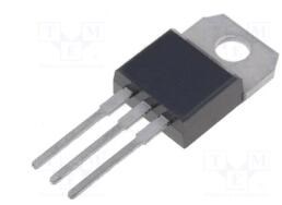 FAQs about TIP32C
26 April 20224134
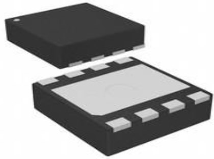 TPS54061DRBT, 60V, Step-Down, MOSFETs, 200mA
24 February 2022289
 AT24C08D I²C-Compatible Serial EEPROM: Pinout, Features and Datasheet
02 April 20221471
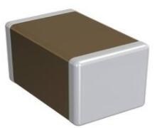 GRM21BR71C475KA73L Ceramic Capacitor: Datasheet, Price, GRM Series
15 March 2022333
 LS404 2.5MHz Quad Op-Amp: Datasheet, Pinout, and Audio Performance Analysis
25 March 2026226
 SPH0641LM4H-1 Digital Microphone: Circuit, Pinout, and Datasheet
23 February 20227373
 TMC2130 Driver IC: Datasheet, Pinout and Application
01 September 20213335
 SiM3C154B/GM 32-bit ARM Cortex-M3 Microcontroller: Technical Overview and Applications
29 February 2024206
 Commonly Used Circuit Protection Components: How to Match the Right Device to Each Threat
30 June 20266408
 What is a Reed Relay?
16 April 20219348
 Challenges in Enhancing Power Electronic Systems with Artificial Intelligence
26 December 20233144
 What is Digital Counter?
01 September 202012915
 Hybrid Sources Powered Electric Vehicles - Part 1
08 March 20233460
 Introduction to Temperature Sensors
24 October 202510152
 How to Address IoT Eco-security in the Era of Digital Transformation?
22 April 2022601
 Selection and Optimization of Peripheral Components for DC-DC Boost Regulator
15 April 20222246
Zilog / Littelfuse
In Stock
United States
China
Canada
Japan
Russia
Germany
United Kingdom
Singapore
Italy
Hong Kong(China)
Taiwan(China)
France
Korea
Mexico
Netherlands
Malaysia
Austria
Spain
Switzerland
Poland
Thailand
Vietnam
India
United Arab Emirates
Afghanistan
Åland Islands
Albania
Algeria
American Samoa
Andorra
Angola
Anguilla
Antigua & Barbuda
Argentina
Armenia
Aruba
Australia
Azerbaijan
Bahamas
Bahrain
Bangladesh
Barbados
Belarus
Belgium
Belize
Benin
Bermuda
Bhutan
Bolivia
Bonaire, Sint Eustatius and Saba
Bosnia & Herzegovina
Botswana
Brazil
British Indian Ocean Territory
British Virgin Islands
Brunei
Bulgaria
Burkina Faso
Burundi
Cabo Verde
Cambodia
Cameroon
Cayman Islands
Central African Republic
Chad
Chile
Christmas Island
Cocos (Keeling) Islands
Colombia
Comoros
Congo
Congo (DRC)
Cook Islands
Costa Rica
Côte d’Ivoire
Croatia
Cuba
Curaçao
Cyprus
Czechia
Denmark
Djibouti
Dominica
Dominican Republic
Ecuador
Egypt
El Salvador
Equatorial Guinea
Eritrea
Estonia
Eswatini
Ethiopia
Falkland Islands
Faroe Islands
Fiji
Finland
French Guiana
French Polynesia
Gabon
Gambia
Georgia
Ghana
Gibraltar
Greece
Greenland
Grenada
Guadeloupe
Guam
Guatemala
Guernsey
Guinea
Guinea-Bissau
Guyana
Haiti
Honduras
Hungary
Iceland
Indonesia
Iran
Iraq
Ireland
Isle of Man
Israel
Jamaica
Jersey
Jordan
Kazakhstan
Kenya
Kiribati
Kosovo
Kuwait
Kyrgyzstan
Laos
Latvia
Lebanon
Lesotho
Liberia
Libya
Liechtenstein
Lithuania
Luxembourg
Macao(China)
Madagascar
Malawi
Maldives
Mali
Malta
Marshall Islands
Martinique
Mauritania
Mauritius
Mayotte
Micronesia
Moldova
Monaco
Mongolia
Montenegro
Montserrat
Morocco
Mozambique
Myanmar
Namibia
Nauru
Nepal
New Caledonia
New Zealand
Nicaragua
Niger
Nigeria
Niue
Norfolk Island
North Korea
North Macedonia
Northern Mariana Islands
Norway
Oman
Pakistan
Palau
Palestinian Authority
Panama
Papua New Guinea
Paraguay
Peru
Philippines
Pitcairn Islands
Portugal
Puerto Rico
Qatar
Réunion
Romania
Rwanda
Samoa
San Marino
São Tomé & Príncipe
Saudi Arabia
Senegal
Serbia
Seychelles
Sierra Leone
Sint Maarten
Slovakia
Slovenia
Solomon Islands
Somalia
South Africa
South Sudan
Sri Lanka
St Helena, Ascension, Tristan da Cunha
St. Barthélemy
St. Kitts & Nevis
St. Lucia
St. Martin
St. Pierre & Miquelon
St. Vincent & Grenadines
Sudan
Suriname
Svalbard & Jan Mayen
Sweden
Syria
Tajikistan
Tanzania
Timor-Leste
Togo
Tokelau
Tonga
Trinidad & Tobago
Tunisia
Turkey
Turkmenistan
Turks & Caicos Islands
Tuvalu
U.S. Outlying Islands
U.S. Virgin Islands
Uganda
Ukraine
Uruguay
Uzbekistan
Vanuatu
Vatican City
Venezuela
Wallis & Futuna
Yemen
Zambia
Zimbabwe
![Z16F2811AL20SG]() Z16F2811AL20SG
Z16F2811AL20SGZilog
![Z8F6423FT020SG]() Z8F6423FT020SG
Z8F6423FT020SGZilog
![EZ80F92AZ020SG]() EZ80F92AZ020SG
EZ80F92AZ020SGZilog
![Z86E4016VSG]() Z86E4016VSG
Z86E4016VSGZilog
![Z86E3016PSG]() Z86E3016PSG
Z86E3016PSGZilog
![Z8F6422AR020SG]() Z8F6422AR020SG
Z8F6422AR020SGZilog
![EZ80L92AZ050SG]() EZ80L92AZ050SG
EZ80L92AZ050SGZilog
![Z8F0811HH020SG]() Z8F0811HH020SG
Z8F0811HH020SGZilog
![Z86E0812SEG]() Z86E0812SEG
Z86E0812SEGZilog
![Z8F2421AN020SG]() Z8F2421AN020SG
Z8F2421AN020SGZilog


