
 Product
 Brand
Brand Articles
 Tools
Tools
Tantalum Capacitors Explained: How They Work, Where They Fit, and How to Use Them Safely
Tantalum Capacitor Manufacturing Process
Catalog
What a Tantalum Capacitor Actually Is
What a Tantalum Capacitor Actually Is
A tantalum capacitor is a type of solid electrolytic capacitor. The starting point is tantalum metal powder that is pressed and sintered into a porous pellet, which becomes the anode. Because the pellet is riddled with internal surface area, a small volume of material exposes an enormous effective electrode area, and that is the root of the technology's headline trait: a lot of capacitance in a tiny part.
Anode, Ta2O5 Dielectric, and Cathode
The dielectric is the key detail, and it is also the most commonly misunderstood. The insulating layer is not the tantalum metal; it is a thin film of tantalum pentoxide (Ta2O5) grown electrochemically on the surface of the sintered anode. This oxide film is what stores energy across its thickness, and its quality and uniformity largely determine the part's performance. On the other side sits the cathode, or counter-electrode, made from either manganese dioxide (MnO2) or a conductive polymer. Kyocera-AVX's technical material on tantalum capacitor construction is a good place to confirm how these layers stack up in a finished device.

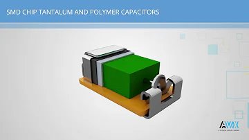
Figure 1. Internal construction of a solid tantalum capacitor. A porous tantalum anode provides a large effective surface area, while a thin Ta2O5 layer acts as the dielectric between the anode and the solid cathode.
Why It Counts as a Solid Electrolytic Capacitor
The word "electrolytic" can be confusing here, because there is no wet electrolyte sloshing around as there is in a classic aluminum can. The MnO2 or polymer layer performs the job the liquid electrolyte does elsewhere: it contacts the oxide dielectric across the porous structure and conducts to the cathode termination. Because that layer is solid, tantalum capacitors do not dry out the way liquid aluminum electrolytics can over time, which is one reason they hold their characteristics well across a long service life.
MnO2 vs Conductive-Polymer Tantalum Capacitors
The choice of cathode material is not a footnote; it is one of the real selection decisions an engineer makes. Traditional parts use manganese dioxide, while newer families use a conductive polymer, and the two behave differently enough that they often suit different jobs.
How the Cathode Changes ESR and Failure Behavior
In broad terms, a conductive-polymer cathode tends to lower equivalent series resistance (ESR) compared with an MnO2 cathode of similar size, which helps in applications that draw fast current transients or care about ripple performance. The cathode system also shapes how the part behaves when it is stressed. KEMET's application notes and Vishay's derating material both describe how the failure behavior and the appropriate derating differ between MnO2 and polymer constructions, so the cathode system is something to read about for the specific family you intend to use rather than assume.

Figure 2. MnO2 and conductive-polymer tantalum capacitors share the same basic tantalum-anode and Ta2O5-dielectric structure, but their cathode materials produce different ESR, transient, and derating characteristics.
Which Cathode Type Fits Which Job
MnO2 parts have a long track record and are often chosen where their behavior is well characterized and cost matters. Polymer parts are frequently favored where low ESR and good transient response are priorities, such as point-of-load decoupling near a processor. The table below summarizes the qualitative trade-offs; the actual ESR and rating numbers belong to the manufacturer datasheet for the part you select.
| Cathode system | Relative ESR | Failure-mode tendency | Typical use | What to confirm in the datasheet |
|---|---|---|---|---|
| Manganese dioxide (MnO2) | Higher | Well-characterized; derating guidance is mature | General filtering, bulk decoupling, cost-sensitive designs | Rated voltage, recommended derating, ripple and temperature limits |
| Conductive polymer | Lower | Different from MnO2; manufacturer specifies its own derating | Low-ESR decoupling, fast transients, ripple-sensitive rails | Rated voltage, ESR, recommended derating, surge handling |
The Characteristics Engineers Care About
Beyond construction, a handful of properties explain why designers reach for tantalum in the first place, and one property explains why they have to be careful.
High Volumetric Efficiency
The sintered, porous anode gives tantalum capacitors high volumetric efficiency: large capacitance for the board space consumed. That makes them attractive where space is tight but a meaningful amount of capacitance is still needed, such as compact handheld and portable designs. Kyocera-AVX and the Texas Instruments capacitor-selection material both treat this density advantage as a defining feature of the technology.
Stable Capacitance vs Temperature and Voltage
Tantalum capacitors hold their capacitance relatively well across temperature and applied voltage. This is a real practical edge over Class II multilayer ceramic capacitors (MLCCs), whose effective capacitance can drop substantially under DC bias and shift with temperature. When you need the capacitance you specified to actually be present under operating conditions, that stability matters. Treat the comparison qualitatively and read the exact coefficients from the datasheet, because they vary by part.
Polarity and Why Reverse Voltage Is Dangerous
Tantalum capacitors are polarized. They are built to be operated with a defined positive and negative terminal, and applying voltage the wrong way round stresses the dielectric in a way it was never designed to tolerate. Murata's note comparing tantalum and aluminum electrolytics describes this rectifying behavior, and NASA's reliability lesson on tantalum parts underscores that reverse bias or misapplication can lead to degradation or worse. This is why polarity is not a detail to confirm casually; it is a first-order constraint that has to be right.
Tantalum vs Aluminum Electrolytic vs MLCC
The most common question readers bring to this topic is simply which technology to use. There is no universal winner; each makes sense in different roles. The table gives a fair side-by-side, and the prose explains how to read it.
| Property | Tantalum | Aluminum electrolytic | MLCC (ceramic) |
|---|---|---|---|
| Volumetric efficiency | High for its size | High in bulk values | Lower per device at high values |
| Polarity | Polarized | Polarized | Non-polarized |
| Stability vs temperature/voltage | Relatively stable | Moderate; can drift and age | Class II drops under DC bias |
| Typical failure behavior | Can short; needs derating | Often opens or loses capacitance over time | Generally benign; can crack mechanically |
| Best-fit role | Stable, space-efficient filtering and decoupling | Bulk energy storage and smoothing | High-frequency bypass, low ESR |
When Tantalum Is the Better Choice
Tantalum tends to win where you want stable, space-efficient capacitance that will not quietly dry out or sag under bias over the product's life. It is a strong fit for filtering, bypass and decoupling, energy storage, and supply smoothing in compact designs, especially where an aluminum electrolytic would be too large or its long-term aging is a concern.
When Aluminum or Ceramic Wins
Aluminum electrolytics are usually the economical choice when you simply need a large bulk capacitance and board space is available, for example at a power-supply input or output. Ceramics shine at high frequency and very low ESR, and their failure mode is generally more benign, so they are natural for local high-frequency bypass. Texas Instruments' capacitor-selection material is a useful neutral reference when weighing these families against one another.
Failure Modes and Why Derating Exists
The cautious reputation of tantalum capacitors is rooted in one real behavior, and understanding it removes the mystery.
The Short-Circuit and Thermal Failure Mode in Plain Terms
The characteristic failure mode of a solid tantalum capacitor is a short circuit rather than a gentle loss of capacitance. AVX's technical information frames this as a low-level but non-negligible possibility, and the concern is what can follow a short: if the part is in a low-impedance, high-current path, the resulting current can produce heat, and in abusive conditions that can escalate to a thermal or ignition risk. The trigger conditions are the predictable ones, namely over-voltage, excessive inrush, high ripple, and reverse bias.
Voltage Derating and Surge/Inrush Limiting
This failure behavior is precisely why voltage derating and inrush limiting are standard practice rather than optional polish. Vishay's derating note explains that solid tantalum should not be operated at or above its rated voltage, and that the appropriate amount of derating depends on the circuit and the cathode system. The principle is straightforward even though the numbers are not universal: choose a rated voltage comfortably above the working voltage, limit surge and inrush current in low-impedance rails (often with a small series resistance), and keep ripple current and self-heating within the part's limits. The exact derating percentage, voltage rating, ripple limit, and temperature ceiling come from the manufacturer datasheet for your specific part, because they are defined there and depend on the construction and the circuit.

Figure 3. Tantalum capacitors are most vulnerable when exposed to overvoltage, reverse polarity, excessive inrush, or high ripple current. Voltage derating, correct polarity, current limiting, and thermal checks reduce these stresses.
Selecting and Using Tantalum Capacitors Reliably
With the theory in place, here is how to put it into practice on the bench and in the schematic.
Identifying Polarity and the Positive Terminal
On a tantalum chip capacitor, the marked end is the positive terminal, typically indicated by a bar or stripe printed on the body or a marking on the package. This is the opposite convention from aluminum electrolytics, where the stripe usually marks the negative side, so it is worth checking the specific part's marking convention rather than relying on habit. Confirm the footprint orientation against the datasheet before committing a layout, because a polarity error here is one of the easiest ways to provoke a failure.
A Practical Selection and Handling Checklist
The factors below map each decision to what you verify and where the authoritative value lives.
| Factor | What to do | Where the number comes from |
|---|---|---|
| Rated voltage and derating | Pick a rating above the working voltage and apply the recommended derating | Manufacturer datasheet (KEMET, Vishay, Panasonic) |
| Inrush and surge | Limit current in low-impedance rails, often with series resistance | Manufacturer application notes |
| Ripple current | Keep ripple and self-heating within the part's limit | Manufacturer datasheet |
| Temperature | Stay inside the rated operating temperature range | Manufacturer datasheet |
| Soldering and thermal handling | Follow the recommended reflow profile and handling guidance | Manufacturer datasheet |
| Polarity | Confirm the positive terminal and footprint orientation | Manufacturer datasheet |
Treat this list as a habit rather than a one-time exercise. The components of reliable tantalum use are not exotic; they are the same disciplined steps applied every time, with the actual figures read from the named manufacturer document.
Frequently Asked Questions
Are tantalum capacitors polarity sensitive?
Yes. They are polarized components with a defined positive and negative terminal, and applying voltage in reverse stresses the dielectric in a way it is not designed for. Always confirm orientation against the part marking and datasheet before powering a board.
Why do some engineers avoid tantalum capacitors?
The main reason is the failure mode: a stressed tantalum part can fail as a short circuit, and in a low-impedance path that can produce heat. Engineers who avoid them are reacting to abuse cases. With proper voltage derating and inrush limiting, the technology is reliable, which is why it remains widely used.
What causes tantalum capacitors to fail?
The usual triggers are over-voltage, reverse bias, excessive inrush current, and high ripple causing self-heating. Each pushes the part beyond what the dielectric and cathode system can tolerate. Staying within rated and derated limits addresses the great majority of these cases.
How can I tell if a capacitor is tantalum, and which end is positive?
Tantalum chip capacitors usually carry a printed bar or stripe marking the positive terminal, the opposite of the aluminum electrolytic convention where the stripe marks the negative side. Confirm the specific part's marking against its datasheet rather than assuming.
Is tantalum more reliable than aluminum electrolytic?
It depends on the failure you care about. Tantalum holds its characteristics over time and does not dry out the way liquid aluminum electrolytics can, but its short-circuit failure mode demands derating. Aluminum parts tend to age and lose capacitance more gradually. Neither is universally more reliable; the right choice depends on the application.
Tantalum or ceramic, which should I choose?
Choose tantalum when you need stable capacitance that holds up under DC bias and temperature in a compact polarized part. Choose a ceramic MLCC for high-frequency bypass, very low ESR, a non-polarized part, or a more benign failure mode. Many designs use both for different jobs.
Do tantalum capacitors need to be derated, and by how much?
Yes, voltage derating is standard practice because of the short-circuit failure mode. The amount is not universal; it depends on the circuit impedance and the cathode system, so take the specific derating guidance from the manufacturer datasheet for the part you are using.
Where are tantalum capacitors commonly used?
Typical roles include filtering, bypass and decoupling, energy storage, and supply smoothing, especially in compact designs where their high capacitance density and stability are valuable.
Sources and Further Reading
Vishay - Derating Tantalum Capacitors Depends on the Cathode System confirms why solid tantalum should not run at or above rated voltage and how derating depends on the cathode system, though the exact derating amounts apply to Vishay's own families rather than every part.
Kyocera-AVX - Tantalum Capacitors: Characteristics and Components is a clear reference on construction, characteristics, and selection considerations, with the caveat that specific ratings are part-dependent.
AVX - Tantalum Technical Information supports the stability and short-circuit failure-mode discussion, while noting it reflects one manufacturer's product line.
Murata - Comparison Between Tantalum and Aluminum helps confirm the shared polarized behavior of tantalum and aluminum electrolytics, though it is framed around Murata's perspective.
Texas Instruments - Types of Capacitors (selection material) offers a neutral comparison of capacitor families to weigh tantalum against aluminum and ceramic, at an introductory level of detail.
NASA - Lesson Learned 981 reinforces that most tantalum capacitors are polarity sensitive and that misapplication can cause catastrophic failure, drawn from spaceflight reliability experience rather than general commercial use.
KEMET and Panasonic datasheets and application notes are the authoritative source for exact voltage ratings, derating curves, ripple and temperature limits, and handling guidance, which always depend on the specific part you select.
 UTMEL
UTMEL
We are the professional distributor of electronic components, providing a large variety of products to save you a lot of time, effort, and cost with our efficient self-customized service. careful order preparation fast delivery service
1.What is tantalum capacitor used for?
As a class of electrolytic capacitors, tantalum capacitor is widely used in communications, aerospace and military industries, submarine cables, advanced electronic devices, civil appliances, televisions, and many other aspects. Tantalum capacitors are made of metal tantalum (Ta) as the anode material.
2.What is the difference between tantalum and electrolytic capacitors?
Because of its very thin and relatively high permittivity dielectric layer, the tantalum capacitor distinguishes itself from other conventional and electrolytic capacitors in having high capacitance per volume (high volumetric efficiency) and lower weight. Tantalum capacitors are inherently polarized components.
3.How do you know if a capacitor is tantalum?
Leaded tantalum capacitor markings: Leaded tantalum capacitors generally have their values marked in microfarads, µF. Typically the markings on a capacitor may give the figures like 22 and 6V. This indicates a 22µF capacitor with a maximum voltage of 6V.
4.What can replace tantalum capacitor?
Ceramic capacitors are probably the most frequently used substitute for tantalum-chip capacitors, VP Beck said. Aluminum-electrolytic capacitors are also viable options in some cases, according to Rich Schuster, president of NIC Components Corp. (Melville, N.Y.).
Can I replace a tantalum capacitor with a ceramic capacitor?
A low-ESR ceramic output capacitor with a discrete series resistor can be used to replace a tantalum output capacitor.
 AI Server MLCCs: Why NVIDIA Rubin Racks Require Over 600,000 CapacitorsUTMEL02 June 20261529
Next-generation AI servers like NVIDIA's Rubin architecture require over 600,000 MLCCs per rack due to extreme power densities exceeding 120kW. This transition from GB300 demands high-capacitance, low-ESR capacitors with X7R/X7S dielectrics to handle intense transient responses and thermal loads, forcing procurement teams to navigate extended 24-week lead times for these specialized components.
Read More What is Feedthrough Capacitor?UTMEL06 November 202141025
Hello, everyone. I am Rose. Today I will introduce the feedthrough capacitor to you. The feedthrough capacitor is a three-terminal capacitor that is used to reduce high frequencies. The feedthrough capacitor, unlike regular three-terminal capacitors, is directly installed on the metal panel, resulting in a lower grounding inductance and a negligible effect on the lead inductance.
Read More Detailed Explanation About Twenty Kinds of CapacitorUTMEL08 November 20219141
Hello everyone, I am Rose. Today I will introduce 20 kinds of capacitor to you. I will illustrate them in three or four aspects: Structure, features, Usages, advantages and disadvantages.
Read More What is a Polypropylene Capacitor?UTMEL08 November 202121440
A polypropylene capacitor is a kind of capacitor with a very stable electric capacity. It is often used in applications requiring very precise capacitance and can replace most polyphenylene or mica capacitors.
Read More What is the Difference between MOM, MIM and MOS Capacitors?UTMEL17 April 202569522
This article mainly introduces the structure, principle, advantages and disadvantages of MOM, MIM and MOS capacitors and the difference between them.
Read More
Subscribe to Utmel !
![6AV63722DF070CH0]() 6AV63722DF070CH0
6AV63722DF070CH0Siemens
![5403]() 5403
5403Adafruit Industries LLC
![RTKYZ014A0B00000BE]() RTKYZ014A0B00000BE
RTKYZ014A0B00000BERenesas Electronics America Inc
![DS320PR810-RSC-EVM]() DS320PR810-RSC-EVM
DS320PR810-RSC-EVMTexas Instruments
![LM5149-Q1EVM-400]() LM5149-Q1EVM-400
LM5149-Q1EVM-400Texas Instruments
![MIKROE-5262]() MIKROE-5262
MIKROE-5262MikroElektronika
![US159-DA16200MEVZ]() US159-DA16200MEVZ
US159-DA16200MEVZRenesas Electronics America Inc
![EVALM7LVMOSINVTOBO1]() EVALM7LVMOSINVTOBO1
EVALM7LVMOSINVTOBO1Infineon Technologies
![SEK-SHT41I-AD1B-SENSORS]() SEK-SHT41I-AD1B-SENSORS
SEK-SHT41I-AD1B-SENSORSSensirion AG
![EVL012LED]() EVL012LED
EVL012LEDSTMicroelectronics
