
 Product
 Brand
Brand Articles
 Tools
Tools
Power Transformer Basics and Operation Cautions

Power Transformers: Basic Design and Function
Catalog
I What is a Power Transformer and How does it Work?
A power transformer is a static electrical device that is used to change a certain value of AC voltage (current) into another or several voltages (current) with the same frequency. It is a necessary equipment for power transmission and distribution and power distribution for power users.
When the primary winding is energized with alternating current, alternating magnetic flux is produced. The alternating magnetic flux passes through the iron core and induces an alternating electromotive force in the secondary winding. The level of the secondary induced electromotive force is related to the number of turns of the primary and secondary windings, that is, the voltage is proportional to the number of turns.
The main function of the power transformer is to transmit electric energy, therefore, the rated capacity is its main parameter. Rated capacity is a customary value representing power. It represents the magnitude of the transmitted electrical energy, expressed in kVA or MVA. When a rated voltage is applied to the transformer, the value is used to determine the rated current that does not exceed the temperature rise limit under specified conditions.
II Technical Terms of Power Transformers
(1) Rated capacity: the guaranteed value of the output capacity of the transformer under rated operating conditions. which is:
S=1.73×ULIL×10-3 (kVA)
Where:
UL-voltage on the low-voltage side of the transformer (V);
IL-current on the low-voltage side of the transformer (A);
(2) Rated voltage: The primary and secondary voltage values specified by the transformer's insulation strength and allowable temperature rise under the transformer's rated operating conditions.
Coil temperature rise: the difference between the temperature of the transformer and the temperature of the surrounding medium.
For Oil-immersed Transformer
(1) Coil temperature rise: 65℃ (the maximum temperature of the cooling medium is 40℃);
(2) Oil temperature rise: 55℃ (the highest top oil temperature is 95℃, and the highest temperature of the cooling medium is 40℃).
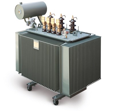
Figure 1. Oil-immersed Transformer
For Dry-type Transformer
(1) Coil temperature rise: 100°C (Class F insulation), 80°C (Class B insulation), and the ambient temperature is not more than 40°C.
(2) Impedance voltage: It's also called short-circuit voltage, which is the applied voltage when one coil is short-circuited and the other coil reaches the rated current, generally expressed as a percentage of the rated voltage.
The magnitude of the short-circuit voltage value is extremely important in the operation of the transformer. It is the basis for considering the short-circuit current, the characteristics of the relay protection, and the parallel connection of the transformer.
(3) Short-circuit loss: The loss (in W or kW) that occurs when the rated current passes one coil and the other coil is short-circuited. It's the loss caused by the current passing through the resistor, that is, copper loss.
(4) No-load loss: the loss of the transformer in the no-load state (due to the small no-load current and primary winding resistance, the copper loss is negligible, and it is basically equal to the iron loss).
(5) No-load current: It refers to the current passing through when the secondary winding of the transformer is open, and the primary winding is applied with the rated voltage of the rated frequency. It is usually expressed as a percentage of the rated current: I0%=I0/IN×100%. The larger the transformer capacity, the smaller the no-load current.
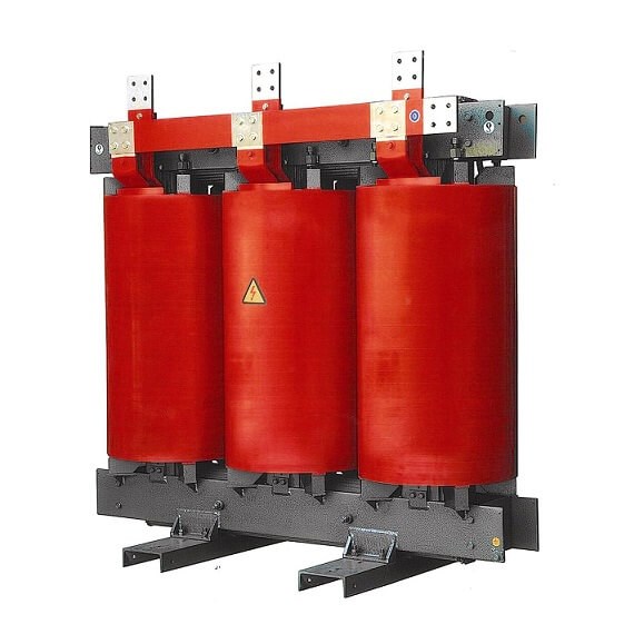
Figure 2. Dry-type Transformer
III Power Transformer Construction
The primary and secondary coils of an ordinary transformer are concentrically cased in an iron core column, with low-voltage windings inside and high-voltage windings outside.
When the transformer is running with a load, when the secondary side current increases, the transformer must maintain the main magnetic flux in the core unchanged, and the primary side current must also increase accordingly to balance the secondary side current.
Generally, the transformer secondary active power = transformer rated capacity (KVA) × 0.8 (transformer power factor) = KW.
The power transformers are mainly composed of:
(1) Moisture absorber (silicon tube): There is silica gel inside. The insulating oil in the oil conservator is connected to the atmosphere through the moisture absorber, and the desiccant absorbs moisture and impurities in the air to keep the internal windings of the transformer in good condition. Discoloration and deterioration of silica gel can easily cause a blockage.
(2) Oil level gauge: it reflects the oil level of the transformer, generally around +20O. If the level is too high, the oil needs to be drained, and if it is too low, we should add a little. The oil level will not change much, or the oil level will drop slightly in winter when the temperature is low and the load is light. In summer, when the load is heavy, the oil temperature rises and the oil level rises slightly, both of which are normal.
(3) Oil pillow: adjust the amount of oil in the oil tank to prevent the transformer oil from over-oxidizing. There is an oil filling port on the upper part.
(4) Explosion-proof pipe: to prevent sudden accidents from causing pressure buildup in the fuel tank, resulting in an explosion hazard.
(5) Signal thermometer: monitor the operating temperature of the transformer and send out a signal. It indicates the upper oil temperature of the transformer, and the temperature of the transformer coil is 10°C higher than the upper oil temperature.
The national standard stipulates: the limit working temperature of the transformer winding is 105℃(that is, when the ambient temperature is 40℃), the upper layer temperature should not exceed 95℃, and the monitoring temperature (upper oil temperature) is usually set at 85℃ and below.
(6) Tap changer: change the voltage ratio by changing the tap of the high-voltage winding and increasing or decreasing the number of winding turns.
∵ U1/U2=W1/W2, U1W2=U2W1,
∴ U2=U1W2/W1.
Generally, transformers perform no-load voltage regulation when the power is off. Normally, the regulation is divided into three gears Ⅰ, Ⅱ, and Ⅲ, which are respectively +5%, 0%, -5% (10.5KV, 10KV, 0.95KV for the primary winding and 380V, 400V, 420V for the secondary winding). It is usually set to Ⅱ gear when leaving the factory.
(7) Gas signal relay: used for light gas and heavy gas signal protection. The upper contact is a light gas signal, which is generally used as a signal alarm to indicate the abnormal operation of the transformer. The lower contact is a heavy gas signal, and when the signal is sent out, the circuit breaker trips, drops, and alarms.
Generally, if the gas relay is filled with oil, there will be no gas in the fuel tank. If there is gas, it will enter the relay. When it reaches a certain level, the gas squeezes away the oil and makes the contacts act.
Open the cover of the gas relay and you'll see two adjusting rods on the top. Unscrew one of the caps to release the gas inside the relay. The other adjusting rod is a protective test button. Insulated gloves must be worn in the hot-line work.
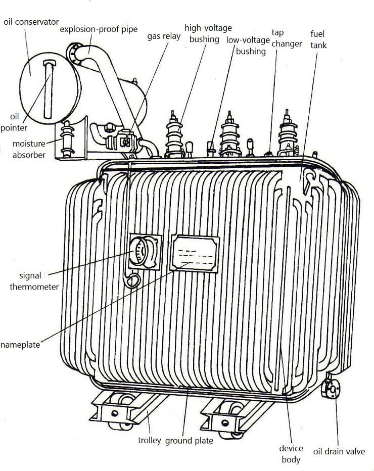
Figure 3. Outline Diagram of Three-phase Oil-immersed Power Transformer
IV Power Transformer Classification
1. According to the Purpose
There are step-up power transformers(6.3kV/10.5kV or 10.5kV/110kV in power plants, etc.), contact power transformers(220kV/110kV or 110kV/10.5kV between substations), and step-down power transformers(35kV/0.4kV or 10.5kV/0.4kV).
2. According to the Number of Phases
There are single-phase power transformers and three-phase power transformers.
3. According to Windings
There are dual-winding power transformers(each phase is installed on the same core, the primary and secondary windings are separately wound and insulated from each other), three-winding power transformers (each phase has three windings, the primary and secondary windings are separately wound and insulated from each other), autotransformers (the tap in the middle of a set of winding is used as the primary or secondary output).
A Three-winding transformer requires the capacity of the primary winding to be greater than or equal to the capacity of the secondary and tertiary windings. The percentage of the capacity of the three windings in the order of high voltage, medium voltage, and low voltage is: 100/100/100, 100/50/100, 100/100/50, and the second and tertiary windings cannot be operated at full load.
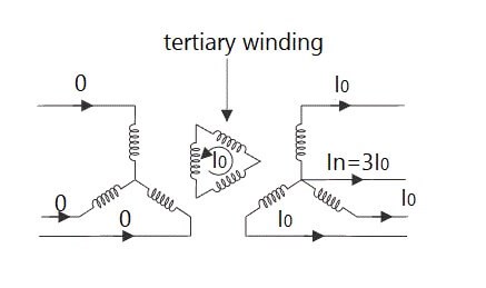
Figure 4. Diagram of Three-winding Transformer
Generally, the voltage of the tertiary winding is low, and it is mostly used for power supply in the near area or connected to compensation equipment, and used for connecting three voltage levels.
Autotransformer: There are two types of step-up or step-down. Because of its small loss, lightweight and economical use, it is widely used in ultra-high-voltage power grids. The commonly used model of the small autotransformer is 400V/36V (24V), which is used to supply power for equipment such as safety lighting.
According to the insulating medium: oil-immersed transformers (flame-retardant, non-flame-retardant), dry-type transformers, and gas-insulated transformers.
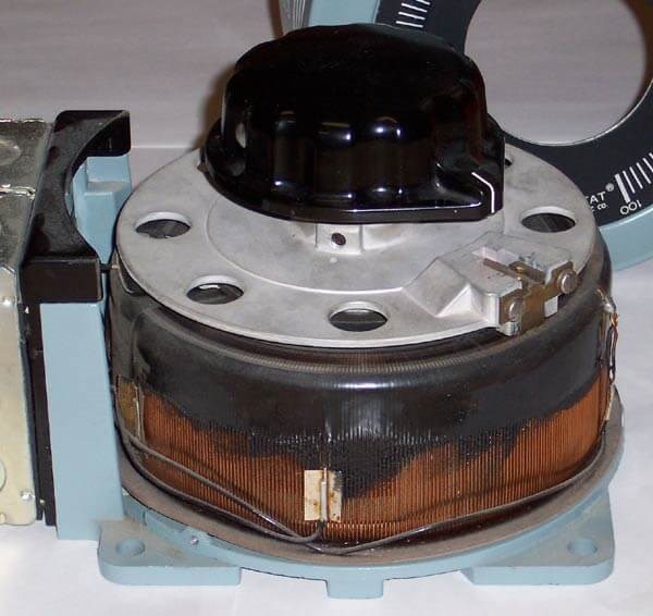
Figure 5. Variable Autotransformer
V Oil Leakage Problem
1. Oil Leakage at the Weld
It is mainly due to poor welding, causing false welding, desoldering, pinholes, blisters, and other defects in the weld. The power transformer is covered with welding flux and paint when it leaves the factory, and hidden dangers are exposed after the operation. In addition, electromagnetic vibration will cause welding vibration and leakage.
For leaks that have already occurred, we should first find out the leaking point. For severe leakage, metal tools such as a flat shovel or sharp punch can be used to rivet the leakage point. After the amount of leakage is controlled, the treatment surface will be cleaned up. Most of the polymer composite materials are used for curing long-term treatment.
2. Oil Leakage from the Seal
The reason for poor sealing is that the seal between the rim and the cover is usually sealed with oil-resistant rubber rods or rubber gaskets. If the joints are not handled properly, it will cause oil leakage.
Some joints are tied with plastic straps, and some are directly pressed together. Due to the rolling during installation, the interface cannot be pressed firmly, and the sealing effect is not achieved, and it is still leaking oil. If the operation is convenient, the metal shell can be bonded to control the leakage.
3. Oil Leakage at the Flange Junction
If the flange surface is not flat, the fastening bolts are loose, the installation process is not correct, and the bolts are not fastened properly, the oil leakage will occur. Tighten the loose bolts and seal the flange and the bolts that may leak. The loose bolts must be tightened in strict accordance with the operating process.
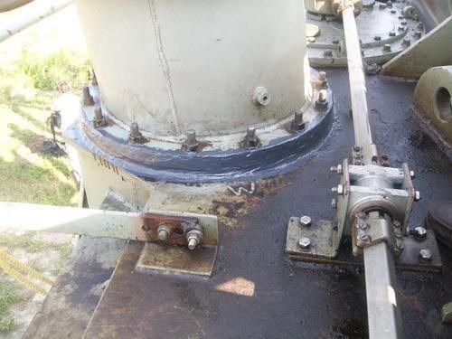
Figure 6. Power Transformer Oil Leakage
4. Oil Leakage from Bolts or Pipe Threads
If the processing is rough and the sealing is not good when leaving the factory, the oil leakage fault will easily occur after the power transformer is sealed for a period of time. The bolts are sealed with polymer materials to control the leakage. Another method is to unscrew the bolts (nuts), apply an agent on the surface for curing.
5. Oil Leakage from Cast Iron
The main cause of oil leakage is blisters and cracks in the cast iron. For crack leakage, drilling crack holes is the best way to eliminate stress and avoid extension. According to the crack condition, lead wire can be inserted into the leaking point or riveted with a hammer. Then use acetone to clean the leak point and seal it with the material. Casting sand holes can be directly sealed with materials.
6. Oil Leakage from the Radiator
The heat pipe of the radiator is usually flattened with seamed steel pipes and then pressed. Oil leakage often occurs in the bent and welded parts of the heat pipe. This is because when the heat pipe is pressed, the outer wall of the pipe is under tension and the inner wall is pressed, producing residual stress. Close the upper and lower plate valves (butterfly valves) of the radiator to isolate the oil in the radiator from the oil in the tank, reducing pressure and leakage. After confirming the leaking part, carry out proper surface treatment and sealing treatment.
7. Leaking Oil from Porcelain Bottles and Glass Oil Pointers
It is usually caused by improper installation or seal failure. Polymer composite materials can bond metals, ceramics, glass, and other materials well to achieve the fundamental treatment of oil leakage.
VI Grounding of Power Transformer
1. The outer shell of the transformer should be grounded reliably, the working neutral wire and neutral ground wire should be laid separately, and the working neutral wire should not be buried underground.
2. The connecting bolts near the transformer of the neutral ground loop of the transformer should be detachable.
3. The grounding of a transformer equipped with a valve arrester should meet the following requirements: the neutral point of the transformer, the transformer housing, and the grounding of the arrester should be connected at one place and grounded together.
4. The grounding resistance should be less than 4 ohms.
VII Fire and Explosion Protection
Power transformers are the main equipment for power transmission and distribution in power systems. The power transformer reduces the high-voltage power of the grid to 6000 volts (V) or 380 volts (V) that can be used directly, which is supplied to electrical equipment.
If an overload or short circuit occurs inside the transformer, the insulating material or insulating oil will decompose due to high temperature or electric sparks. It then expands and even vaporizes, making the internal pressure of the transformer increase sharply, which may cause the transformer shell to explode and a large amount of insulating oil will be sprayed and burned. Oil flow will further aggravate the fire hazard.
Figure 7. Fire and Explosion Prevention of Power Transformers
Pay attention to fire and explosion protection during operation:
(1) No overload operation: Long-term overload operation will cause the coil to heat up, which will make the insulation to gradually age and cause a short circuit.
(2) Insulating oil quality should be checked frequently: oil quality should be tested regularly, and unqualified oil should be replaced in time.
(3) Prevent the insulation aging of the transformer core, which is caused by the long-term heating of the core.
(4) Prevent the insulation from being damaged due to careless maintenance. If a scratch is found, deal with it in time.
(5) Ensure that the wires are in good contact. Poor contact will cause local overheating.
(6) Prevent lightning strikes. The transformer will burn out due to insulation breakdown.
(7) Short-circuit protection. If the transformer coil or load is short-circuited, if the protection system fails or the protection setting is too large, the transformer may be burned. To deal with it, reliable short-circuit protection should be installed.
(8) Well-protected grounding.
(9) Ventilation and cooling. Maintain good ventilation and cooling when the transformer is running. If the transformer coil wire is A-class insulation, the insulator is mainly paper and cotton yarn. When the temperature rises by 8°C, the insulation life will be reduced by about half. If the normal temperature of the transformer is below 90°C, the life span is about 20 years; if the temperature rises to 105°C, the life span is 7 years.
 UTMEL
UTMEL
We are the professional distributor of electronic components, providing a large variety of products to save you a lot of time, effort, and cost with our efficient self-customized service. careful order preparation fast delivery service
1.What is the use of power transformer?
The Power transformer is a one kind of transformer, that is used to transfer electrical energy in any part of the electrical or electronic circuit between the generator and the distribution primary circuits. These transformers are used in distribution systems to interface step up and step down voltages.
2.What is meant by power transformer?
Power Transformer is an electrical device that converts inbound electricity to a higher or lower value of voltage for specific purposes. It is a major component in power grid to supply voltage in many nations. The two main functions of the transformers are: To supply current from source to destination.
3.How do power transformers work?
The core of the transformer works to direct the path of the magnetic field between the primary and secondary coils to prevent wasted energy. Once the magnetic field reaches the secondary coil, it forces the electrons within it to move, creating an electric current via electromotive force (EMF).
4.What are the 3 types of transformers?
There are three primary types of voltage transformers (VT): electromagnetic, capacitor, and optical.
5.What are the two main types of transformer?
The different types of transformer are step up and step down transformer, power transformer, distribution transformer, instrument transformer, single phase and three phase transformer, auto transformer, etc.
 What is a Transformer: Definition, Principle and ApplicationsUTMEL03 November 20218366
Hi, fellas. I am Rose. Today I will introduce the transformer to you. The device that increases or decreases the voltage in an AC circuit is known as a transformer. The transformer is an AC voltage converter that works on the mutual inductance concept.
Read More LVDT - Linear Variable Differential Transformer BasicsUTMEL16 January 20219372
LVDT is the abbreviation of linear variable differential transformer, which belongs to linear displacement sensor. It is a movable iron core transformer that consists of a primary coil, two secondary coils, iron core, coil frame, shell and other components.
Read More Introduction to Flyback TransformerUTMEL29 January 202111826
As an energy conversion device that transfers energy from one part of the circuit to the other part at constant power, a flyback transformer can be described. Based on the application, the voltage is stepped up to a very high value in a flyback transformer. It is also called a transformer for line output, as the voltage of the output line is fed to the other part of the circuit. The primary winding of the transformer can be powered by a DC circuit with the assistance of the rectifying circuit.
Read More Audio Transformer-Types, Functions and WorkingUTMEL05 January 202615350
An audio transformer is an electromagnetic system designed to separate an input circuit from an output circuit and produce a signal that passes through it with filtering. A varying electromotive force (voltage) in the secondary winding linked to the other circuit is caused by this changing flux.
Read More Basics") RVDT(Rotary Variable Differential Transformer) BasicsUTMEL02 February 202120547
RVDT(Rotary Variable Differential Transformer) BasicsUTMEL02 February 202120547The Rotary Variable Differential Transformer or RVDT is regarded as the transformer that detects the angular displacement of the conductor. That is the kind of electromechanical transducer that gives the angular displacement of the input equal to the linear output.
Read More
Subscribe to Utmel !
![BLE32PN300SN1L]() BLE32PN300SN1L
BLE32PN300SN1LMurata Electronics
![01220083Z]() 01220083Z
01220083ZLittelfuse Inc.
![PKM22EPPH4001-B0]() PKM22EPPH4001-B0
PKM22EPPH4001-B0Murata Electronics
![EMK105BJ105KV-F]() EMK105BJ105KV-F
EMK105BJ105KV-FTaiyo Yuden
![01110501Z]() 01110501Z
01110501ZLittelfuse Inc.
![AC0603FR-071KL]() AC0603FR-071KL
AC0603FR-071KLYageo
![AC0402FR-071KL]() AC0402FR-071KL
AC0402FR-071KLYageo
![AVR-M1005C080MTABB]() AVR-M1005C080MTABB
AVR-M1005C080MTABBTDK Corporation
![CL31B475KBHNFNE]() CL31B475KBHNFNE
CL31B475KBHNFNESamsung Electro-Mechanics
![HMC794LP3E]() HMC794LP3E
HMC794LP3EAnalog Devices Inc.


