
 Product
 Brand
Brand Articles
 Tools
Tools
AT24C32 Two-Wire Serial EEPROM: Datasheet, Pinout and Address


3/5V V Memory IC AT24C32 9.271mm mm
AT24C32 IC is a Serial Electrically Erasable PROM of 4K x 8 (32Kbit). This article mainly covers pinout, datasheet, address, Arduino, applications, and more details about AT24C32. Furthermore, there is a huge range of semiconductors, capacitors, resistors, and Ics in stock. Welcome your RFQ!

Tiny RTC I2C AT24C32 DS1307 Real Time Clock Module Board with CR2032 Battery for Arduino
What is AT24C32?
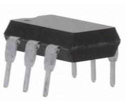
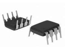
The AT24C32 IC is a 4K x 8 Serial Electrically Erasable PROM (32Kbit). It was created with low-power advanced applications in mind, such as personal communications and data collecting. It's an 8-pin plastic DIP package and an 8-pin surface mount SOIC package.
AT24C32 Pinout

AT24C32 Pinout
| Pin Number | Pin Name | Description |
| 1,2,3 | A0,A1,A2 | User configured Chip Select pins, useful during cascading |
| 4 | Vss (Ground) | Connected to the ground of the circuit |
| 5 | Serial Data (SDA) | Serial Data pin for I2C Communication |
| 6 | Serial Clock (SCL) | Serial Clock pin for I2C Communication |
| 7 | WP (Write Protect) | If connected to Vss write is enabled, if connected to Vcc write is disabled. |
| 8 | Vcc | Connect to supply rail |
AT24C32 CAD Model
Footprint

AT24C32 Footprint
3D Model

AT24C32 3D Model
AT24C32 Block Diagram

AT24C32 Block Diagram
Specifications
- TypeParameter
- Mounting Type
The "Mounting Type" in electronic components refers to the method used to attach or connect a component to a circuit board or other substrate, such as through-hole, surface-mount, or panel mount.
Through Hole - Package / Case
refers to the protective housing that encases an electronic component, providing mechanical support, electrical connections, and thermal management.
8-DIP (0.300, 7.62mm) - Surface Mount
having leads that are designed to be soldered on the side of a circuit board that the body of the component is mounted on.
NO - Memory TypesNon-Volatile
- Operating Temperature
The operating temperature is the range of ambient temperature within which a power supply, or any other electrical equipment, operate in. This ranges from a minimum operating temperature, to a peak or maximum operating temperature, outside which, the power supply may fail.
-40°C~85°C TA - Packaging
Semiconductor package is a carrier / shell used to contain and cover one or more semiconductor components or integrated circuits. The material of the shell can be metal, plastic, glass or ceramic.
Tube - Published1998
- JESD-609 Code
The "JESD-609 Code" in electronic components refers to a standardized marking code that indicates the lead-free solder composition and finish of electronic components for compliance with environmental regulations.
e0 - Part Status
Parts can have many statuses as they progress through the configuration, analysis, review, and approval stages.
Obsolete - Moisture Sensitivity Level (MSL)
Moisture Sensitivity Level (MSL) is a standardized rating that indicates the susceptibility of electronic components, particularly semiconductors, to moisture-induced damage during storage and the soldering process, defining the allowable exposure time to ambient conditions before they require special handling or baking to prevent failures
1 (Unlimited) - Number of Terminations8
- ECCN Code
An ECCN (Export Control Classification Number) is an alphanumeric code used by the U.S. Bureau of Industry and Security to identify and categorize electronic components and other dual-use items that may require an export license based on their technical characteristics and potential for military use.
EAR99 - Terminal Finish
Terminal Finish refers to the surface treatment applied to the terminals or leads of electronic components to enhance their performance and longevity. It can improve solderability, corrosion resistance, and overall reliability of the connection in electronic assemblies. Common finishes include nickel, gold, and tin, each possessing distinct properties suitable for various applications. The choice of terminal finish can significantly impact the durability and effectiveness of electronic devices.
TIN LEAD - Additional Feature
Any Feature, including a modified Existing Feature, that is not an Existing Feature.
DATA RETENTION: 100 YEARS - HTS Code
HTS (Harmonized Tariff Schedule) codes are product classification codes between 8-1 digits. The first six digits are an HS code, and the countries of import assign the subsequent digits to provide additional classification. U.S. HTS codes are 1 digits and are administered by the U.S. International Trade Commission.
8542.32.00.51 - Voltage - Supply
Voltage - Supply refers to the range of voltage levels that an electronic component or circuit is designed to operate with. It indicates the minimum and maximum supply voltage that can be applied for the device to function properly. Providing supply voltages outside this range can lead to malfunction, damage, or reduced performance. This parameter is critical for ensuring compatibility between different components in a circuit.
4.5V~5.5V - Terminal Position
In electronic components, the term "Terminal Position" refers to the physical location of the connection points on the component where external electrical connections can be made. These connection points, known as terminals, are typically used to attach wires, leads, or other components to the main body of the electronic component. The terminal position is important for ensuring proper connectivity and functionality of the component within a circuit. It is often specified in technical datasheets or component specifications to help designers and engineers understand how to properly integrate the component into their circuit designs.
DUAL - Peak Reflow Temperature (Cel)
Peak Reflow Temperature (Cel) is a parameter that specifies the maximum temperature at which an electronic component can be exposed during the reflow soldering process. Reflow soldering is a common method used to attach electronic components to a circuit board. The Peak Reflow Temperature is crucial because it ensures that the component is not damaged or degraded during the soldering process. Exceeding the specified Peak Reflow Temperature can lead to issues such as component failure, reduced performance, or even permanent damage to the component. It is important for manufacturers and assemblers to adhere to the recommended Peak Reflow Temperature to ensure the reliability and functionality of the electronic components.
NOT SPECIFIED - Number of Functions1
- Supply Voltage
Supply voltage refers to the electrical potential difference provided to an electronic component or circuit. It is crucial for the proper operation of devices, as it powers their functions and determines performance characteristics. The supply voltage must be within specified limits to ensure reliability and prevent damage to components. Different electronic devices have specific supply voltage requirements, which can vary widely depending on their design and intended application.
3V - Terminal Pitch
The center distance from one pole to the next.
2.54mm - Time@Peak Reflow Temperature-Max (s)
Time@Peak Reflow Temperature-Max (s) refers to the maximum duration that an electronic component can be exposed to the peak reflow temperature during the soldering process, which is crucial for ensuring reliable solder joint formation without damaging the component.
NOT SPECIFIED - Base Part Number
The "Base Part Number" (BPN) in electronic components serves a similar purpose to the "Base Product Number." It refers to the primary identifier for a component that captures the essential characteristics shared by a group of similar components. The BPN provides a fundamental way to reference a family or series of components without specifying all the variations and specific details.
AT24C32 - JESD-30 Code
JESD-30 Code refers to a standardized descriptive designation system established by JEDEC for semiconductor-device packages. This system provides a systematic method for generating designators that convey essential information about the package's physical characteristics, such as size and shape, which aids in component identification and selection. By using JESD-30 codes, manufacturers and engineers can ensure consistency and clarity in the specification of semiconductor packages across various applications and industries.
R-PDIP-T8 - Qualification Status
An indicator of formal certification of qualifications.
Not Qualified - Supply Voltage-Max (Vsup)
The parameter "Supply Voltage-Max (Vsup)" in electronic components refers to the maximum voltage that can be safely applied to the component without causing damage. It is an important specification to consider when designing or using electronic circuits to ensure the component operates within its safe operating limits. Exceeding the maximum supply voltage can lead to overheating, component failure, or even permanent damage. It is crucial to adhere to the specified maximum supply voltage to ensure the reliable and safe operation of the electronic component.
5.5V - Power Supplies
an electronic circuit that converts the voltage of an alternating current (AC) into a direct current (DC) voltage.?
3/5V - Supply Voltage-Min (Vsup)
The parameter "Supply Voltage-Min (Vsup)" in electronic components refers to the minimum voltage level required for the component to operate within its specified performance range. This parameter indicates the lowest voltage that can be safely applied to the component without risking damage or malfunction. It is crucial to ensure that the supply voltage provided to the component meets or exceeds this minimum value to ensure proper functionality and reliability. Failure to adhere to the specified minimum supply voltage may result in erratic behavior, reduced performance, or even permanent damage to the component.
2.7V - Memory Size
The memory capacity is the amount of data a device can store at any given time in its memory.
32Kb 4K x 8 - Operating Mode
A phase of operation during the operation and maintenance stages of the life cycle of a facility.
SYNCHRONOUS - Clock Frequency
Clock frequency, also known as clock speed, refers to the rate at which a processor or electronic component can execute instructions. It is measured in hertz (Hz) and represents the number of cycles per second that the component can perform. A higher clock frequency typically indicates a faster processing speed and better performance. However, it is important to note that other factors such as architecture, efficiency, and workload also play a significant role in determining the overall performance of a component. In summary, clock frequency is a crucial parameter that influences the speed and efficiency of electronic components in processing data and executing tasks.
400kHz - Supply Current-Max
Supply Current-Max refers to the maximum amount of current that an electronic component or circuit can draw from its power supply under specified operating conditions. It is a critical parameter that determines the power consumption and thermal performance of the device. Exceeding this limit can lead to overheating, potential damage, or failure of the component. Knowing the Supply Current-Max helps in designing circuits that ensure proper operation and reliability.
0.003mA - Access Time
Access time in electronic components refers to the amount of time it takes for a system to retrieve data from memory or storage once a request has been made. It is typically measured in nanoseconds or microseconds and indicates the speed at which data can be accessed. Lower access time values signify faster performance, allowing for more efficient processing in computing systems. Access time is a critical parameter in determining the overall responsiveness of electronic devices, particularly in applications requiring quick data retrieval.
900ns - Memory Format
Memory Format in electronic components refers to the specific organization and structure of data storage within a memory device. It defines how data is stored, accessed, and managed within the memory module. Different memory formats include RAM (Random Access Memory), ROM (Read-Only Memory), and various types of flash memory. The memory format determines the speed, capacity, and functionality of the memory device, and it is crucial for compatibility with other components in a system. Understanding the memory format is essential for selecting the right memory module for a particular application or device.
EEPROM - Memory Interface
An external memory interface is a bus protocol for communication from an integrated circuit, such as a microprocessor, to an external memory device located on a circuit board.
I2C - Organization
In the context of electronic components, the parameter "Organization" typically refers to the arrangement or structure of the internal components within a device or system. It can describe how various elements such as transistors, resistors, capacitors, and other components are physically arranged and interconnected on a circuit board or within a semiconductor chip.The organization of electronic components plays a crucial role in determining the functionality, performance, and efficiency of a device. It can impact factors such as signal propagation, power consumption, thermal management, and overall system complexity. Engineers carefully design the organization of components to optimize the operation of electronic devices and ensure reliable performance.Different types of electronic components may have specific organizational requirements based on the intended application and design considerations. For example, integrated circuits may have a highly compact and intricate organization to maximize functionality within a small footprint, while larger electronic systems may have a more modular and distributed organization to facilitate maintenance and scalability.
4KX8 - Output Characteristics
Output characteristics in electronic components refer to the relationship between the output voltage and output current across a range of input conditions. This parameter is essential for understanding how a device, such as a transistor or operational amplifier, behaves under various loads and operating points. It provides insights into the efficiency, performance, and limitations of the component, helping designers to make informed choices for circuits and applications.
OPEN-DRAIN - Memory Width
Memory width refers to the number of bits that can be read or written to memory at one time. It is an important specification in electronic components, particularly in memory devices like RAM and cache. A wider memory width allows for greater data throughput, enabling faster performance as more data can be processed simultaneously. Memory width can vary among different types of memory and can impact both the complexity and efficiency of data handling within electronic systems.
8 - Write Cycle Time - Word, Page
Write Cycle Time - Word, Page refers to the duration required to write data to a specific memory cell or a page of memory in electronic components, particularly in non-volatile memories like Flash or EEPROM. It indicates the time taken to complete a writing operation for a single word or an entire page of data. This parameter is crucial for determining the performance and speed of memory devices in applications where quick data storage is essential. It impacts the overall efficiency in data handling, affecting both read and write speeds in memory-related operations.
10ms - Standby Current-Max
Standby Current-Max refers to the maximum amount of current that an electronic component or device consumes while in a low-power standby mode. This parameter is critical for power management, especially in battery-operated devices, as it indicates how efficiently the device can conserve energy when not actively in use. A lower Standby Current-Max value is typically desirable, as it contributes to longer battery life and reduced energy consumption. Manufacturers specify this value to help engineers select components that meet specific power efficiency requirements in their designs.
5e-7A - Memory Density
Memory density in electronic components refers to the amount of data that can be stored in a given physical space or memory module. It is typically measured in bits or bytes per unit area, such as bits per square inch. Higher memory density means that more data can be stored in a smaller space, which is important for devices with limited physical size or power constraints. Memory density is a key factor in determining the capacity and performance of memory devices, such as RAM, ROM, and flash memory, and is a critical consideration in the design and manufacturing of electronic products.
32768 bit - Parallel/Serial
The parameter "Parallel/Serial" in electronic components refers to the method of data transmission or communication within the component. In parallel communication, multiple bits of data are transmitted simultaneously over multiple channels or wires. This allows for faster data transfer rates but requires more physical connections and can be more susceptible to signal interference.On the other hand, in serial communication, data is transmitted sequentially over a single channel or wire. While serial communication may have slower data transfer rates compared to parallel communication, it is more cost-effective, requires fewer connections, and is less prone to signal interference.The choice between parallel and serial communication depends on the specific requirements of the electronic component and the overall system design, balancing factors such as speed, cost, complexity, and reliability.
SERIAL - Serial Bus Type
Serial bus type refers to the method by which data is transmitted between components in an electronic system using a serial communication protocol. It involves the sequential transfer of data bits over a single channel or wire, allowing for a reduced number of interconnections compared to parallel communication. Common examples of serial bus types include I2C, SPI, USB, and UART, each with its own specific protocol and applications. The choice of serial bus type can affect the speed, complexity, and power consumption of the communication between devices.
I2C - Endurance
In electronic components, "Endurance" refers to the ability of a component to withstand repeated cycles of operation without degradation in performance or failure. It is a crucial parameter, especially in components that are subjected to frequent switching or high levels of stress during operation. Endurance testing is often conducted to evaluate the reliability and durability of electronic components under real-world conditions. Components with high endurance ratings are more likely to have a longer lifespan and provide consistent performance over time. Manufacturers typically provide endurance specifications in datasheets to help engineers and designers select components that meet the required durability for their applications.
1000000 Write/Erase Cycles - Write Cycle Time-Max (tWC)
The parameter "Write Cycle Time-Max (tWC)" in electronic components refers to the maximum amount of time it takes for data to be written to a memory cell or storage device. It is a crucial specification in devices such as EEPROMs, flash memory, and other non-volatile memory technologies. The tWC value indicates the longest duration required for a write operation to be completed successfully, ensuring that the data is stored accurately and reliably. Designers and engineers use this parameter to optimize performance and ensure proper functioning of the electronic component within the specified time constraints.
10ms - Data Retention Time-Min
The parameter "Data Retention Time-Min" in electronic components refers to the minimum amount of time that data can be stored in a non-volatile memory device without requiring a refresh or rewrite operation to maintain its integrity. This parameter is crucial for applications where data integrity and reliability are essential, such as in embedded systems, IoT devices, and critical infrastructure. A longer data retention time indicates a more stable memory device that can retain data for extended periods without degradation or loss. It is important to consider the data retention time when selecting memory components for specific applications to ensure data reliability and longevity.
100 - Write Protection
Write protection is a feature found in electronic components, such as memory devices, that prevents data from being modified or erased. When write protection is enabled, the data stored in the component is locked and cannot be altered, ensuring the integrity and security of the information. This feature is commonly used in devices like USB flash drives, SD cards, and EEPROMs to prevent accidental data loss or unauthorized access. Write protection can be implemented through hardware mechanisms, such as physical switches or jumpers, or through software settings that restrict write access to the component.
HARDWARE - I2C Control Byte
The I2C Control Byte is a specific byte of data used in the Inter-Integrated Circuit (I2C) communication protocol for electronic components. It is a crucial part of the data transmission process as it contains information such as the address of the device being accessed and the type of operation to be performed, such as read or write. The Control Byte is typically the first byte sent in an I2C communication sequence and helps establish communication between the master and slave devices on the bus. By interpreting the Control Byte, devices can effectively communicate and exchange data in a synchronized manner within an I2C network.
1010DDDR - Length9.271mm
- Height Seated (Max)
Height Seated (Max) is a parameter in electronic components that refers to the maximum allowable height of the component when it is properly seated or installed on a circuit board or within an enclosure. This specification is crucial for ensuring proper fit and alignment within the overall system design. Exceeding the maximum seated height can lead to mechanical interference, electrical shorts, or other issues that may impact the performance and reliability of the electronic device. Manufacturers provide this information to help designers and engineers select components that will fit within the designated space and function correctly in the intended application.
5.334mm - Width7.62mm
- RoHS Status
RoHS means “Restriction of Certain Hazardous Substances” in the “Hazardous Substances Directive” in electrical and electronic equipment.
Non-RoHS Compliant
AT24C32 Features
Supply Voltage: 1.8V to 5.5V DC
Supply Current – Max: 2 MA
Memory Size: 4K x 8 (32Kbit)
Organization: 4 k x 8=32kbit
Interface Type: Serial, 2-Wire, and I2C
Max Clock Frequency: 40 kHz
32-Byte Page Write Mode feature
Self-timed write cycle feature
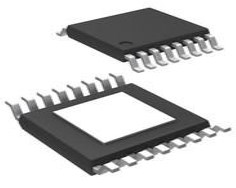
8-pin PDIP, SOIC, and TSSOP available packages
AT24C32 Equivalents
24LC512, 24C04
Alternatives for AT24C32
24LC1026, AT24C256, 25LC050
AT24C32 Applications
Data Logging
Audio devices
Data analytics
Storage devices
Remote storage devices
Used where Flash memory of MCU is less
Where to use AT24C32
The AT24C32 EEPROM IC is a serial electrically erasable and programmable read-only memory chip with 32 bits (EEPROM). The cascadable feature of the device allows up to eight devices to share a common 2-wire bus. The operational voltage range of this IC is 1.8V to 5.5V, making it suitable for both 3.3V and 5V systems. The AT24C32 has a 32Kbit memory area and uses a 2-Wire Serial Interface. If you need a low-power, low-voltage EEPROM, this is the IC to utilize.
How to use AT24C32
It has a simple interface that allows you to connect it to a microcontroller with only 5 pins. The AT24C32 IC's interface schematic is shown below.

Pin 6 of the AT24C32 IC is connected to the microcontroller's Serial clock pin, while Serial Data pin 5 is connected to the microcontroller's Serial Data pin (SDA). Two pull-up resistors are used to pull the SCK and SDA pins high (4.7k). During the off-season, this will maintain the bus running at a high level.
Select pins A0, A1, and A2 are only useful if multiple EEPROMs are attached to the same microcontroller; otherwise, these pins can be directly grounded. We've linked the three pins to the PIO pins in the circuit diagram above so that we can utilize more than one EEPROM IC if necessary.
In the AT24C32 IC, Pin 7 is used to improve data security. Only when the WP pin is held low can data be written or deleted (logic 0). The data written to the EEPROM, on the other hand, will remain unmodified.
AT24C32 Dimensions

AT24C32 Dimensions
AT24C32 Manufacturer
Microchip Technology Inc. is a leader that provides microcontroller and analog semiconductors. The microchip was headquartered in Chandler, Arizona. We are dedicated to offering low-risk product development, reducing total system cost, and accelerating time to market. We mainly serve different fields of customers applications around the world. To provide prominent technical support along with reliable delivery and quality is our goal.
Datasheet PDF
- Datasheets :
- PCN Packaging :
What is the use of AT24C32?
AT24C32 is a 4K x 8 (32Kbit) Serial Electrically Erasable PROM. This IC is specially designed for advanced, low-power applications such as personal communications or data acquisition. It is available in the standard 8-pin plastic DIP, and 8-pin surface mounts SOIC packages.
Can the AT24C32 chip card replace the 24LC32 chip on the circuit board?
Yes, the same is EEROM.
What is the use of at24c32 in the stm32 microcontroller circuit?
It is used to store data.
 4N36 Optocoupler: Datasheet, Pinout, 4N35 vs.4N36 vs.4N37
25 October 20213896
 BC177 Low Power PNP Transistor: Datasheet pdf, Pinout and Equivalents
02 December 20212868
 AD581: High-Precision Voltage Reference for Reliable Electronic Systems
06 March 2024232
 OP07 Operational Amplifier: Pinout, Datasheet, OP07 VS LM308
15 December 202110722
 TPS2H160BQPWPRQ1 High-Side Switch: Layout, Pinout, and Datasheet
19 April 20221780
 AT24C08D I²C-Compatible Serial EEPROM: Pinout, Features and Datasheet
02 April 20221441
 Discovering the NXP LPC3141/3143 Microcontroller: A Technical Analysis
29 February 2024269
 Optimizing the AD7124 24-Bit ADC: Solving Startup Delays and Design Challenges
10 March 2026226
 Parallel Plate Capacitor: Features, Working Principle and Applications
30 January 20218685
 Introduction to PIC Microcontroller: Architecture, Features, and Applications
08 April 202513262
 RTD Sensors: Working Principle, Features and Applications
22 May 202513367
 An Artificial Brain Chip With 86 Billion Physical Neurons
31 March 20225420
 What is UWB (Ultra-wideband)?
04 June 20218337
 AI Server MLCCs: Why NVIDIA Rubin Racks Require Over 600,000 Capacitors
02 June 2026708
 Cellular IoT Transmit Module for Enhanced Connectivity and Power Efficiency with Extended Battery Life
30 January 20242246
 How New Battery Charger Technology is Shaping the Future
10 July 20251168
Microchip Technology
In Stock
United States
China
Canada
Japan
Russia
Germany
United Kingdom
Singapore
Italy
Hong Kong(China)
Taiwan(China)
France
Korea
Mexico
Netherlands
Malaysia
Austria
Spain
Switzerland
Poland
Thailand
Vietnam
India
United Arab Emirates
Afghanistan
Åland Islands
Albania
Algeria
American Samoa
Andorra
Angola
Anguilla
Antigua & Barbuda
Argentina
Armenia
Aruba
Australia
Azerbaijan
Bahamas
Bahrain
Bangladesh
Barbados
Belarus
Belgium
Belize
Benin
Bermuda
Bhutan
Bolivia
Bonaire, Sint Eustatius and Saba
Bosnia & Herzegovina
Botswana
Brazil
British Indian Ocean Territory
British Virgin Islands
Brunei
Bulgaria
Burkina Faso
Burundi
Cabo Verde
Cambodia
Cameroon
Cayman Islands
Central African Republic
Chad
Chile
Christmas Island
Cocos (Keeling) Islands
Colombia
Comoros
Congo
Congo (DRC)
Cook Islands
Costa Rica
Côte d’Ivoire
Croatia
Cuba
Curaçao
Cyprus
Czechia
Denmark
Djibouti
Dominica
Dominican Republic
Ecuador
Egypt
El Salvador
Equatorial Guinea
Eritrea
Estonia
Eswatini
Ethiopia
Falkland Islands
Faroe Islands
Fiji
Finland
French Guiana
French Polynesia
Gabon
Gambia
Georgia
Ghana
Gibraltar
Greece
Greenland
Grenada
Guadeloupe
Guam
Guatemala
Guernsey
Guinea
Guinea-Bissau
Guyana
Haiti
Honduras
Hungary
Iceland
Indonesia
Iran
Iraq
Ireland
Isle of Man
Israel
Jamaica
Jersey
Jordan
Kazakhstan
Kenya
Kiribati
Kosovo
Kuwait
Kyrgyzstan
Laos
Latvia
Lebanon
Lesotho
Liberia
Libya
Liechtenstein
Lithuania
Luxembourg
Macao(China)
Madagascar
Malawi
Maldives
Mali
Malta
Marshall Islands
Martinique
Mauritania
Mauritius
Mayotte
Micronesia
Moldova
Monaco
Mongolia
Montenegro
Montserrat
Morocco
Mozambique
Myanmar
Namibia
Nauru
Nepal
New Caledonia
New Zealand
Nicaragua
Niger
Nigeria
Niue
Norfolk Island
North Korea
North Macedonia
Northern Mariana Islands
Norway
Oman
Pakistan
Palau
Palestinian Authority
Panama
Papua New Guinea
Paraguay
Peru
Philippines
Pitcairn Islands
Portugal
Puerto Rico
Qatar
Réunion
Romania
Rwanda
Samoa
San Marino
São Tomé & Príncipe
Saudi Arabia
Senegal
Serbia
Seychelles
Sierra Leone
Sint Maarten
Slovakia
Slovenia
Solomon Islands
Somalia
South Africa
South Sudan
Sri Lanka
St Helena, Ascension, Tristan da Cunha
St. Barthélemy
St. Kitts & Nevis
St. Lucia
St. Martin
St. Pierre & Miquelon
St. Vincent & Grenadines
Sudan
Suriname
Svalbard & Jan Mayen
Sweden
Syria
Tajikistan
Tanzania
Timor-Leste
Togo
Tokelau
Tonga
Trinidad & Tobago
Tunisia
Turkey
Turkmenistan
Turks & Caicos Islands
Tuvalu
U.S. Outlying Islands
U.S. Virgin Islands
Uganda
Ukraine
Uruguay
Uzbekistan
Vanuatu
Vatican City
Venezuela
Wallis & Futuna
Yemen
Zambia
Zimbabwe
![24LC16BT-I/OT]() 24LC16BT-I/OT
24LC16BT-I/OTMicrochip Technology
![AT93C46DN-SH-T]() AT93C46DN-SH-T
AT93C46DN-SH-TMicrochip Technology
![24LC32AT-I/SN]() 24LC32AT-I/SN
24LC32AT-I/SNMicrochip Technology
![AT24C01C-SSHM-T]() AT24C01C-SSHM-T
AT24C01C-SSHM-TMicrochip Technology
![AT24C04D-SSHM-T]() AT24C04D-SSHM-T
AT24C04D-SSHM-TMicrochip Technology
![AT93C66B-SSHM-T]() AT93C66B-SSHM-T
AT93C66B-SSHM-TMicrochip Technology
![AT25020B-SSHL-T]() AT25020B-SSHL-T
AT25020B-SSHL-TMicrochip Technology
![23K256T-I/SN]() 23K256T-I/SN
23K256T-I/SNMicrochip Technology
![AT93C46D-PU]() AT93C46D-PU
AT93C46D-PUMicrochip Technology
![24LC16BT-I/SN]() 24LC16BT-I/SN
24LC16BT-I/SNMicrochip Technology


