
 Product
 Brand
Brand Articles
 Tools
Tools
ATmega128L 8-bit Atmel Microcontroller: How to use the ATmega128L?

128KB 64K x 16 FLASH AVR 8-Bit Microcontroller AVR® ATmega Series ATMEGA128 64 Pin 8MHz 3V 64-TQFP


128KB 64K x 16 FLASH AVR 8-Bit Microcontroller AVR® ATmega Series ATMEGA128 64 Pin 8MHz 3V 64-TQFP
ATmega128L is a 8-bit Atmel Microcontroller. This article is going to talk about the pinout, features, applications, and more detailed information about ATmega128L.
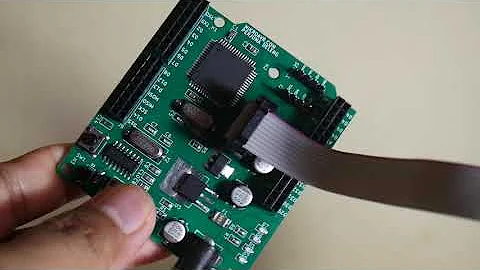
Arduino ATMega128
ATmega128L Description
AVR RISC architecture is the foundation of Microchip's ATMEGA128L, an 8-bit microcontroller with outstanding performance and low power consumption. Although hobbyists and developers may not be as familiar with this microcontroller, if you're searching for a Microchip AVR series microcontroller with medium power and an affordable price, this could be a perfect option for you.
ATmega128L Features
Operating Voltage: 2.7 - 5.5V ATmega128L
Frequency Grade: 0 - 8MHz ATmega128L
High Endurance Non-volatile Memory segments
128Kbytes of In-System Self-programmable Flash program memory
4Kbytes EEPROM
4Kbytes Internal SRAM
Write/Erase cycles: 10,000 Flash/100,000 EEPROM
Two 8-bit PWM Channels
6 PWM Channels with Programmable Resolution from 2 to 16 Bits
8-channel, 10-bit ADC
Master/Slave SPI Serial Interface
Two Expanded 16-bit Timer/Counters with Separate Prescaler, Compare Mode, and Capture Mode
Programmable Watchdog Timer with On-chip Oscillator
On-chip Analog Comparator
Two 8-bit Timer/Counters with Separate Prescaler
Dual Programmable Serial USARTs
Internal Calibrated RC Oscillator
Software Selectable Clock Frequency
JTAG (IEEE std. 1149.1 Compliant) Interface with Boundary Scan, on-chip debugging
Optional Boot Code Section with Independent Lock Bits
In-System Programming by On-chip Boot Program
Data retention: 20 years at 85°C/100 years at 25°C
Specifications
- TypeParameter
- Factory Lead Time7 Weeks
- Contact Plating
Contact plating (finish) provides corrosion protection for base metals and optimizes the mechanical and electrical properties of the contact interfaces.
Tin - Mount
In electronic components, the term "Mount" typically refers to the method or process of physically attaching or fixing a component onto a circuit board or other electronic device. This can involve soldering, adhesive bonding, or other techniques to secure the component in place. The mounting process is crucial for ensuring proper electrical connections and mechanical stability within the electronic system. Different components may have specific mounting requirements based on their size, shape, and function, and manufacturers provide guidelines for proper mounting procedures to ensure optimal performance and reliability of the electronic device.
Surface Mount - Mounting Type
The "Mounting Type" in electronic components refers to the method used to attach or connect a component to a circuit board or other substrate, such as through-hole, surface-mount, or panel mount.
Surface Mount - Package / Case
refers to the protective housing that encases an electronic component, providing mechanical support, electrical connections, and thermal management.
64-TQFP - Number of Pins64
- Manufacturer Package Identifier
The Manufacturer Package Identifier is a unique code or label assigned by the manufacturer to identify a specific package or housing style of an electronic component. This identifier helps in distinguishing between different package types of the same component, such as integrated circuits, transistors, or diodes. It typically includes information about the package dimensions, lead configuration, and other physical characteristics of the component. The Manufacturer Package Identifier is crucial for ensuring compatibility and proper assembly of electronic components in various devices and circuits.
64A - Data ConvertersA/D 8x10b
- Number of I/Os53
- Watchdog TimersYes
- Operating Temperature
The operating temperature is the range of ambient temperature within which a power supply, or any other electrical equipment, operate in. This ranges from a minimum operating temperature, to a peak or maximum operating temperature, outside which, the power supply may fail.
-40°C~85°C TA - Packaging
Semiconductor package is a carrier / shell used to contain and cover one or more semiconductor components or integrated circuits. The material of the shell can be metal, plastic, glass or ceramic.
Tray - Series
In electronic components, the "Series" refers to a group of products that share similar characteristics, designs, or functionalities, often produced by the same manufacturer. These components within a series typically have common specifications but may vary in terms of voltage, power, or packaging to meet different application needs. The series name helps identify and differentiate between various product lines within a manufacturer's catalog.
AVR® ATmega - Published1997
- JESD-609 Code
The "JESD-609 Code" in electronic components refers to a standardized marking code that indicates the lead-free solder composition and finish of electronic components for compliance with environmental regulations.
e3 - Pbfree Code
The "Pbfree Code" parameter in electronic components refers to the code or marking used to indicate that the component is lead-free. Lead (Pb) is a toxic substance that has been widely used in electronic components for many years, but due to environmental concerns, there has been a shift towards lead-free alternatives. The Pbfree Code helps manufacturers and users easily identify components that do not contain lead, ensuring compliance with regulations and promoting environmentally friendly practices. It is important to pay attention to the Pbfree Code when selecting electronic components to ensure they meet the necessary requirements for lead-free applications.
yes - Part Status
Parts can have many statuses as they progress through the configuration, analysis, review, and approval stages.
Active - Moisture Sensitivity Level (MSL)
Moisture Sensitivity Level (MSL) is a standardized rating that indicates the susceptibility of electronic components, particularly semiconductors, to moisture-induced damage during storage and the soldering process, defining the allowable exposure time to ambient conditions before they require special handling or baking to prevent failures
3 (168 Hours) - Number of Terminations64
- Terminal Position
In electronic components, the term "Terminal Position" refers to the physical location of the connection points on the component where external electrical connections can be made. These connection points, known as terminals, are typically used to attach wires, leads, or other components to the main body of the electronic component. The terminal position is important for ensuring proper connectivity and functionality of the component within a circuit. It is often specified in technical datasheets or component specifications to help designers and engineers understand how to properly integrate the component into their circuit designs.
QUAD - Terminal Form
Occurring at or forming the end of a series, succession, or the like; closing; concluding.
GULL WING - Peak Reflow Temperature (Cel)
Peak Reflow Temperature (Cel) is a parameter that specifies the maximum temperature at which an electronic component can be exposed during the reflow soldering process. Reflow soldering is a common method used to attach electronic components to a circuit board. The Peak Reflow Temperature is crucial because it ensures that the component is not damaged or degraded during the soldering process. Exceeding the specified Peak Reflow Temperature can lead to issues such as component failure, reduced performance, or even permanent damage to the component. It is important for manufacturers and assemblers to adhere to the recommended Peak Reflow Temperature to ensure the reliability and functionality of the electronic components.
260 - Supply Voltage
Supply voltage refers to the electrical potential difference provided to an electronic component or circuit. It is crucial for the proper operation of devices, as it powers their functions and determines performance characteristics. The supply voltage must be within specified limits to ensure reliability and prevent damage to components. Different electronic devices have specific supply voltage requirements, which can vary widely depending on their design and intended application.
3V - Frequency
In electronic components, the parameter "Frequency" refers to the rate at which a signal oscillates or cycles within a given period of time. It is typically measured in Hertz (Hz) and represents how many times a signal completes a full cycle in one second. Frequency is a crucial aspect in electronic components as it determines the behavior and performance of various devices such as oscillators, filters, and communication systems. Understanding the frequency characteristics of components is essential for designing and analyzing electronic circuits to ensure proper functionality and compatibility with other components in a system.
8MHz - Time@Peak Reflow Temperature-Max (s)
Time@Peak Reflow Temperature-Max (s) refers to the maximum duration that an electronic component can be exposed to the peak reflow temperature during the soldering process, which is crucial for ensuring reliable solder joint formation without damaging the component.
40 - Base Part Number
The "Base Part Number" (BPN) in electronic components serves a similar purpose to the "Base Product Number." It refers to the primary identifier for a component that captures the essential characteristics shared by a group of similar components. The BPN provides a fundamental way to reference a family or series of components without specifying all the variations and specific details.
ATMEGA128 - Voltage
Voltage is a measure of the electric potential difference between two points in an electrical circuit. It is typically represented by the symbol "V" and is measured in volts. Voltage is a crucial parameter in electronic components as it determines the flow of electric current through a circuit. It is responsible for driving the movement of electrons from one point to another, providing the energy needed for electronic devices to function properly. In summary, voltage is a fundamental concept in electronics that plays a key role in the operation and performance of electronic components.
5V - Interface
In electronic components, the term "Interface" refers to the point at which two different systems, devices, or components connect and interact with each other. It can involve physical connections such as ports, connectors, or cables, as well as communication protocols and standards that facilitate the exchange of data or signals between the connected entities. The interface serves as a bridge that enables seamless communication and interoperability between different parts of a system or between different systems altogether. Designing a reliable and efficient interface is crucial in ensuring proper functionality and performance of electronic components and systems.
2-Wire, I2C, SPI, USART - Memory Size
The memory capacity is the amount of data a device can store at any given time in its memory.
128kB - Oscillator Type
Wien Bridge Oscillator; RC Phase Shift Oscillator; Hartley Oscillator; Voltage Controlled Oscillator; Colpitts Oscillator; Clapp Oscillators; Crystal Oscillators; Armstrong Oscillator.
Internal - RAM Size
RAM size refers to the amount of random access memory (RAM) available in an electronic component, such as a computer or smartphone. RAM is a type of volatile memory that stores data and instructions that are actively being used by the device's processor. The RAM size is typically measured in gigabytes (GB) and determines how much data the device can store and access quickly for processing. A larger RAM size allows for smoother multitasking, faster loading times, and better overall performance of the electronic component. It is an important factor to consider when choosing a device, especially for tasks that require a lot of memory, such as gaming, video editing, or running multiple applications simultaneously.
4K x 8 - Voltage - Supply (Vcc/Vdd)
Voltage - Supply (Vcc/Vdd) is a key parameter in electronic components that specifies the voltage level required for the proper operation of the device. It represents the power supply voltage that needs to be provided to the component for it to function correctly. This parameter is crucial as supplying the component with the correct voltage ensures that it operates within its specified limits and performance characteristics. It is typically expressed in volts (V) and is an essential consideration when designing and using electronic circuits to prevent damage and ensure reliable operation.
2.7V~5.5V - uPs/uCs/Peripheral ICs Type
The parameter "uPs/uCs/Peripheral ICs Type" refers to the classification of various integrated circuits used in electronic devices. It encompasses microprocessors (uPs), microcontrollers (uCs), and peripheral integrated circuits that provide additional functionalities. This classification helps in identifying the specific type of chip used for processing tasks, controlling hardware, or interfacing with other components in a system. Understanding this parameter is essential for selecting the appropriate electronic components for a given application.
MICROCONTROLLER, RISC - Core Processor
The term "Core Processor" typically refers to the central processing unit (CPU) of a computer or electronic device. It is the primary component responsible for executing instructions, performing calculations, and managing data within the system. The core processor is often considered the brain of the device, as it controls the overall operation and functionality. It is crucial for determining the speed and performance capabilities of the device, as well as its ability to handle various tasks and applications efficiently. In modern devices, core processors can have multiple cores, allowing for parallel processing and improved multitasking capabilities.
AVR - Peripherals
In the context of electronic components, "Peripherals" refer to devices or components that are connected to a main system or device to enhance its functionality or provide additional features. These peripherals can include input devices such as keyboards, mice, and touchscreens, as well as output devices like monitors, printers, and speakers. Other examples of peripherals include external storage devices, network adapters, and cameras. Essentially, peripherals are external devices that expand the capabilities of a main electronic system or device.
Brown-out Detect/Reset, POR, PWM, WDT - Program Memory Type
Program memory typically refers to flash memory when it is used to hold the program (instructions). Program memory may also refer to a hard drive or solid state drive (SSD). Contrast with data memory.
FLASH - Core Size
Core size in electronic components refers to the physical dimensions of the core material used in devices such as inductors and transformers. The core size directly impacts the performance characteristics of the component, including its inductance, saturation current, and frequency response. A larger core size typically allows for higher power handling capabilities and lower core losses, while a smaller core size may result in a more compact design but with limitations on power handling and efficiency. Designers must carefully select the core size based on the specific requirements of the application to achieve optimal performance and efficiency.
8-Bit - Program Memory Size
Program Memory Size refers to the amount of memory available in an electronic component, such as a microcontroller or microprocessor, that is used to store program instructions. This memory is non-volatile, meaning that the data stored in it is retained even when the power is turned off. The program memory size determines the maximum amount of code that can be stored and executed by the electronic component. It is an important parameter to consider when selecting a component for a specific application, as insufficient program memory size may limit the functionality or performance of the device.
128KB 64K x 16 - Connectivity
In electronic components, "Connectivity" refers to the ability of a component to establish and maintain connections with other components or devices within a circuit. It is a crucial parameter that determines how easily signals can be transmitted between different parts of a circuit. Connectivity can be influenced by factors such as the number of input and output ports, the type of connectors used, and the overall design of the component. Components with good connectivity are essential for ensuring reliable and efficient operation of electronic systems.
EBI/EMI, I2C, SPI, UART/USART - Bit Size
In electronic components, "Bit Size" refers to the number of bits that can be processed or stored by a particular component. A bit is the smallest unit of data in computing and can have a value of either 0 or 1. The Bit Size parameter is commonly used to describe the capacity or performance of components such as microprocessors, memory modules, and data buses. A larger Bit Size generally indicates a higher processing capability or storage capacity, allowing for more complex operations and larger amounts of data to be handled efficiently. It is an important specification to consider when selecting electronic components for specific applications that require certain levels of performance and data processing capabilities.
8 - Access Time
Access time in electronic components refers to the amount of time it takes for a system to retrieve data from memory or storage once a request has been made. It is typically measured in nanoseconds or microseconds and indicates the speed at which data can be accessed. Lower access time values signify faster performance, allowing for more efficient processing in computing systems. Access time is a critical parameter in determining the overall responsiveness of electronic devices, particularly in applications requiring quick data retrieval.
8 μs - Has ADC
Has ADC refers to the presence of an Analog-to-Digital Converter (ADC) in an electronic component. An ADC is a crucial component in many electronic devices as it converts analog signals, such as voltage or current, into digital data that can be processed by a digital system. Having an ADC allows the electronic component to interface with analog signals and convert them into a format that can be manipulated and analyzed digitally. This parameter is important for applications where analog signals need to be converted into digital form for further processing or control.
YES - DMA Channels
DMA (Direct Memory Access) Channels are a feature found in electronic components such as microcontrollers, microprocessors, and peripheral devices. DMA Channels allow data to be transferred directly between peripherals and memory without involving the CPU, thereby reducing the burden on the CPU and improving overall system performance. Each DMA Channel is typically assigned to a specific peripheral device or memory region, enabling efficient data transfer operations. The number of DMA Channels available in a system determines the concurrent data transfer capabilities and can vary depending on the specific hardware design. Overall, DMA Channels play a crucial role in optimizing data transfer efficiency and system performance in electronic devices.
NO - Data Bus Width
The data bus width in electronic components refers to the number of bits that can be transferred simultaneously between the processor and memory. It determines the amount of data that can be processed and transferred in a single operation. A wider data bus allows for faster data transfer speeds and improved overall performance of the electronic device. Common data bus widths include 8-bit, 16-bit, 32-bit, and 64-bit, with higher numbers indicating a larger capacity for data transfer. The data bus width is an important specification to consider when evaluating the speed and efficiency of a computer system or other electronic device.
8b - DAC Channels
DAC Channels refer to the number of independent analog output channels available in a digital-to-analog converter (DAC) electronic component. Each channel can convert a digital input signal into an analog output voltage or current. The number of DAC channels determines how many separate analog signals can be generated simultaneously by the DAC. For example, a DAC with two channels can output two different analog signals at the same time, while a DAC with only one channel can only output a single analog signal. The number of DAC channels is an important specification to consider when selecting a DAC for applications requiring multiple analog outputs.
NO - Number of Timers/Counters4
- Address Bus Width
A computer system has an address bus with 8 parallel lines. This means that the address bus width is 8 bits.
16b - Density
In electronic components, "Density" refers to the mass or weight of a material per unit volume. It is a physical property that indicates how tightly packed the atoms or molecules are within the material. The density of a component can affect its performance and characteristics, such as its strength, thermal conductivity, and electrical properties. Understanding the density of electronic components is important for designing and manufacturing processes to ensure optimal performance and reliability.
1 Mb - EEPROM Size
EEPROM Size refers to the amount of memory capacity available in an Electrically Erasable Programmable Read-Only Memory (EEPROM) chip. This parameter indicates the total storage space in bytes or bits that can be used to store data in a non-volatile manner. The EEPROM size determines the maximum amount of information that can be written, read, and erased from the memory chip. It is an important specification to consider when selecting an EEPROM for a particular application, as it directly impacts the amount of data that can be stored and accessed by the electronic component.
4K x 8 - Number of A/D Converters1
- Number of PWM Channels8
- Height1.2mm
- Length14.1mm
- Width14.1mm
- REACH SVHC
The parameter "REACH SVHC" in electronic components refers to the compliance with the Registration, Evaluation, Authorization, and Restriction of Chemicals (REACH) regulation regarding Substances of Very High Concern (SVHC). SVHCs are substances that may have serious effects on human health or the environment, and their use is regulated under REACH to ensure their safe handling and minimize their impact.Manufacturers of electronic components need to declare if their products contain any SVHCs above a certain threshold concentration and provide information on the safe use of these substances. This information allows customers to make informed decisions about the potential risks associated with using the components and take appropriate measures to mitigate any hazards.Ensuring compliance with REACH SVHC requirements is essential for electronics manufacturers to meet regulatory standards, protect human health and the environment, and maintain transparency in their supply chain. It also demonstrates a commitment to sustainability and responsible manufacturing practices in the electronics industry.
No SVHC - Radiation Hardening
Radiation hardening is the process of making electronic components and circuits resistant to damage or malfunction caused by high levels of ionizing radiation, especially for environments in outer space (especially beyond the low Earth orbit), around nuclear reactors and particle accelerators, or during nuclear accidents or nuclear warfare.
No - RoHS Status
RoHS means “Restriction of Certain Hazardous Substances” in the “Hazardous Substances Directive” in electrical and electronic equipment.
ROHS3 Compliant - Lead Free
Lead Free is a term used to describe electronic components that do not contain lead as part of their composition. Lead is a toxic material that can have harmful effects on human health and the environment, so the electronics industry has been moving towards lead-free components to reduce these risks. Lead-free components are typically made using alternative materials such as silver, copper, and tin. Manufacturers must comply with regulations such as the Restriction of Hazardous Substances (RoHS) directive to ensure that their products are lead-free and environmentally friendly.
Lead Free
ATmega128L Pinout

ATmega128L Pinout
Pin Descriptions
| Pin No | Pin Name | Pin Functions | Description and Secondary Functions |
| 1 | Atmega128L programming enable pin | Atmega128L PEN Pin | programming enable pin for the Serial Programming mode |
| 2 | PE0 | RXD0/(PDI) | PDI/RXD0 (Programming Data Input or UART0 Receive Pin) |
| 3 | PE1 | TXD0/PDO | PDO/TXD0 (Programming Data Output) or UART0 Transmit Pin |
| 4 | PE2 | XCK0/AIN0 | Analog Comparator Positive Input or USART0 external clock input/output |
| 5 | PE3 | OC3A/AIN1 | Analog Comparator Negative Input or Output Compare and PWM Output A for Timer/Counter3 |
| 6 | PE4 | OC3B/INT4 | External Interrupt4 Input or Output Compare and PWM Output B for Timer/Counter3 |
| 7 | PE5 | OC3C/INT5 | External Interrupt 5 Input or Output Compare and PWM Output C for Timer/Counter3 |
| 8 | PE6 | T3/INT6 | External Interrupt 6 Input or Timer/Counter3 Clock Input |
| 9 | PE7 | ICP3/INT7 | External Interrupt 7 Input or Timer/Counter3 Input Capture Pin |
| 10 | PB0 | Atmega128L SPI Slave Select input | SPI Slave Select input |
| 11 | PB1 | SCK | SPI Bus Serial Clock |
| 12 | PB2 | MOSI | SPI Bus Master Output/Slave Input |
| 13 | PB3 | MISO | SPI Bus Master Input/Slave Output |
| 14 | PB4 | OC0 | Output Compare and PWM Output for Timer/Counter0 |
| 15 | PB5 | OC1A | Output Compare and PWM Output A for Timer/Counter1 |
| 16 | PB6 | OC1B | Output Compare and PWM Output B for Timer/Counter1 |
| 17 | PB7 | OC2/OC1C | Output Compare and PWM Output for Timer/Counter2 or Output Compare and PWM Output C for Timer/Counter1 |
| 18 | PG3 | TOSC2 | RTC Oscillator Timer/Counter0 |
| 19 | PG4 | TOSC1/PG4 | RTC Oscillator Timer/Counter0 |
| 20 | Atmega 128L RESET | Atmega RESET Pin | |
| 21 | VCC | VCC | Digital supply voltage |
| 22 | GND | GND | Ground |
| 23 | XTAL2 | XTAL2 | XTAL2 (Chip Clock Oscillator pin 2) |
| 24 | XTAL1 | XTAL1 | XTAL1 (Chip Clock Oscillator pin 2) |
| 25 | PD0 | SCL/I NT0 | External Interrupt0 Input or TWI Serial CLock) |
| 26 | PD1 | SDA/I NT1 | External Interrupt1 Input or TWI Serial Data |
| 27 | PD2 | RXD1/I NT2 | External Interrupt2 Input or UART1 Receive Pin |
| 28 | PD3 | TXD1/I NT3 | External Interrupt3 Input or UART1 Transmit Pin |
| 29 | PD4 | ICP1 | Timer/Counter1 Input Capture Pin |
| 30 | PD5 | XCK1 | USART1 External Clock Input/Output |
| 31 | PD6 | T1 | Timer/Counter1 Clock Input |
| 32 | PD7 | T2 | Timer/Counter2 Clock Input |
| 33 | PG0 | Atmega128L Write strobe to external memory | Write strobe to external memory |
| 34 | PG1 | Atmega128L Read strobe to external memory | Read strobe to external memory |
| 35 | PC0 | A8 | Compatibility mode can be used for External Memory Interface |
| 36 | PC1 | A9 | Compatibility mode can be used for External Memory Interface |
| 37 | PC2 | A10 | Compatibility mode can be used for External Memory Interface |
| 38 | PC3 | A11 | Compatibility mode can be used for External Memory Interface |
| 39 | PC4 | A12 | Compatibility mode can be used for External Memory Interface |
| 40 | PC5 | A13 | Compatibility mode can be used for External Memory Interface |
| 41 | PC6 | A14 | Compatibility mode can be used for External Memory Interface |
| 42 | PC7 | A15 | Compatibility mode can be used for External Memory Interface |
| 43 | PG2 | ALE | ALE is the external data memory Address Latch Enable signal. |
| 44 | PA7 | AD7 | External memory interface address and data bit 7 |
| 45 | PA6 | AD6 | External memory interface address and data bit 6 |
| 46 | PA5 | AD5 | External memory interface address and data bit 5 |
| 47 | PA4 | AD4 | External memory interface address and data bit 4 |
| 48 | PA3 | AD3 | External memory interface address and data bit 3 |
| 49 | PA2 | AD2 | External memory interface address and data bit 2 |
| 50 | PA1 | AD1 | External memory interface address and data bit 1 |
| 51 | PA0 | AD0 | External memory interface address and data bit 0 |
| 52 | VCC | VCC | Digital supply voltage |
| 53 | GND | GND | Ground |
| 54 | PF7 | ADC7/TDI | ADC input channel 7 or JTAG Test Data Input |
| 55 | PF6 | ADC6/TDO | ADC input channel 6 or JTAG Test Data Output |
| 56 | PF5 | ADC5/TMS | ADC input channel 5 or JTAG Test Mode Select |
| 57 | PF4 | ADC4/TCK | ADC input channel 4 or JTAG Test ClocK |
| 58 | PF3 | ADC3 | ADC input channel 3 |
| 59 | PF2 | ADC2 | ADC input channel 2 |
| 60 | PF1 | ADC1 | ADC input channel 1 |
| 61 | PF0 | ADC0 | ADC input channel 0 |
| 62 | AREF | AREF | AREF is the analog reference pin for the A/D Converter |
| 63 | GND | GND | Ground |
| 64 | AVCC | AVCC | AVCC is the supply voltage pin for Port F and the A/D Converter. it should be connected to VCC through a low-pass filter. |
ATmega128L Block Diagram

ATmega128L Block Diagram
ATmega128L Applications
Industrial control systems.
SMPS and Power Regulation systems.
Digital data processing.
Analog signal measuring and manipulations.
Embedded systems like coffee machines, vending machines.
Motor control systems.
Display units.
Peripheral Interface system.
How to Use ATMEGA128L
Microcontrollers like the ATmega128L need to be programmed in order for them to function differently from other microcontrollers. This IC will only use current to conduct internal processes if a program is present. An ATmega128L microcontroller can be programmed in a number of ways, but the most common method is to utilize a USBasp Programmer with AVRDude as the programming interface. This way, you can construct and compile your program to obtain a HEX file. With the aid of the AVRDUDE program, you may dump the HEX on this IC after you receive your HEX file. Using the Arduino as an ISP Programmer is an additional method of configuring this device; if you possess an Arduino, you may browse the web for several examples of how to do so. The next option is for those who do not have an Arduino or an USBasp Programmer, this process is called is Parallel Programming, you have to use the Parallel Port which is only available in older Desktop PCs, if you do not have the port, you can always purchase a PCI Parallel port converter for cheap.

Where to Use ATMEGA128L
Although there is an older version of Arduino that uses the ATmega128L as its primary Controller, as we have already stated, the Atmega128L is not as well known as Arduino. Due to the fact that this controller costs less than the ATmega328P and has a 32 Kbyte program memory. With a watchdog timer to reset in the event of an error, this microcontroller can be used in numerous battery-powered applications. It includes a sophisticated multi-mode PWM output that can be applied to a variety of applications and can be utilized on systems with little interference from humans. Below is a block diagram of the ATmega128L.
ATMEGA128L packaging information

ATmega128L packaging information
Datasheet PDF
- Datasheets :
- TechnicalDrawing :
- PCN Obsolescence/ EOL :
- PCN Packaging :
- PCN Design/Specification :
- ConflictMineralStatement :
Popularity by Region
What is ATmega128?
The ATmega128 is an 8-bit, RISC-based, AVR, low power microcontroller with 64 pins of interface. It is mostly utilized in industrial automation and embedded systems.
How many channels does ATmega128 have?
The high-performance, low-power Microchip 8-bit AVR® RISC-based microcontroller includes an 8-channel 10-bit A/D converter, 4 KB SRAM, 4 KB EEPROM, and a JTAG port for on-chip debugging. It also has 128 KB of programmable flash memory.
How many PWM outputs are there in ATmega128?
Using the ATmega128 PWM Registers Directly. The ATmega168P/328P chip has three PWM timers, controlling 6 PWM outputs.
 LSM6DS3TR: 3.6V, 14-VFLGA Module, Pinout and Datasheet
02 March 20221999
 ATmega48PB/88PB/168PB Microcontroller: Technical Insights
29 February 2024180
 TPS2121RUXR Power Multiplexers: 12-VFQFN, Pinout, Datasheet
07 March 20224717
 AT28HC64BF EEPROM: Pinout, Equivalent and Datasheet
16 February 2022716
 BSS138LT1G Power MOSFET: Pinout, Datasheet, and Applications
23 July 20211881
 LDC1614RGHT LDC: Pinout, Specification, and Datasheet
07 June 20211903
 STM32F413CGU6 Microcontroller: Performance, Features and Applications
16 June 2025355
 A Comprehensive Guide to LTC6907HS6#TRMPBF Programmable Timer and Oscillator
06 March 2024240
 Intel Launches First-of-its-Kind Semiconductor Technician Certificate Program to Address Workforce Shortage
28 September 20233251
 Schottky Diodes: Principle, Functions, and Applications
21 October 202525713
 Solid State Relay Basics: Working, Features and Structure
17 September 20209227
 India's Bold Leap Towards Semiconductor Supremacy
15 September 20233763
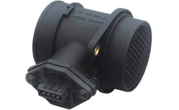 Introduction to Mass Air Flow Sensor
15 September 202010173
 Long Life Small Volume Detector Switch for Intelligent Applications
16 March 20224423
 Hydrogen Fuel Cell: Features, Working and Applications
21 June 20216197
 The Era of Business Globalization: Chinese Founders Aim to Conquer the World
30 May 20227177
Microchip Technology
In Stock: 10
United States
China
Canada
Japan
Russia
Germany
United Kingdom
Singapore
Italy
Hong Kong(China)
Taiwan(China)
France
Korea
Mexico
Netherlands
Malaysia
Austria
Spain
Switzerland
Poland
Thailand
Vietnam
India
United Arab Emirates
Afghanistan
Åland Islands
Albania
Algeria
American Samoa
Andorra
Angola
Anguilla
Antigua & Barbuda
Argentina
Armenia
Aruba
Australia
Azerbaijan
Bahamas
Bahrain
Bangladesh
Barbados
Belarus
Belgium
Belize
Benin
Bermuda
Bhutan
Bolivia
Bonaire, Sint Eustatius and Saba
Bosnia & Herzegovina
Botswana
Brazil
British Indian Ocean Territory
British Virgin Islands
Brunei
Bulgaria
Burkina Faso
Burundi
Cabo Verde
Cambodia
Cameroon
Cayman Islands
Central African Republic
Chad
Chile
Christmas Island
Cocos (Keeling) Islands
Colombia
Comoros
Congo
Congo (DRC)
Cook Islands
Costa Rica
Côte d’Ivoire
Croatia
Cuba
Curaçao
Cyprus
Czechia
Denmark
Djibouti
Dominica
Dominican Republic
Ecuador
Egypt
El Salvador
Equatorial Guinea
Eritrea
Estonia
Eswatini
Ethiopia
Falkland Islands
Faroe Islands
Fiji
Finland
French Guiana
French Polynesia
Gabon
Gambia
Georgia
Ghana
Gibraltar
Greece
Greenland
Grenada
Guadeloupe
Guam
Guatemala
Guernsey
Guinea
Guinea-Bissau
Guyana
Haiti
Honduras
Hungary
Iceland
Indonesia
Iran
Iraq
Ireland
Isle of Man
Israel
Jamaica
Jersey
Jordan
Kazakhstan
Kenya
Kiribati
Kosovo
Kuwait
Kyrgyzstan
Laos
Latvia
Lebanon
Lesotho
Liberia
Libya
Liechtenstein
Lithuania
Luxembourg
Macao(China)
Madagascar
Malawi
Maldives
Mali
Malta
Marshall Islands
Martinique
Mauritania
Mauritius
Mayotte
Micronesia
Moldova
Monaco
Mongolia
Montenegro
Montserrat
Morocco
Mozambique
Myanmar
Namibia
Nauru
Nepal
New Caledonia
New Zealand
Nicaragua
Niger
Nigeria
Niue
Norfolk Island
North Korea
North Macedonia
Northern Mariana Islands
Norway
Oman
Pakistan
Palau
Palestinian Authority
Panama
Papua New Guinea
Paraguay
Peru
Philippines
Pitcairn Islands
Portugal
Puerto Rico
Qatar
Réunion
Romania
Rwanda
Samoa
San Marino
São Tomé & Príncipe
Saudi Arabia
Senegal
Serbia
Seychelles
Sierra Leone
Sint Maarten
Slovakia
Slovenia
Solomon Islands
Somalia
South Africa
South Sudan
Sri Lanka
St Helena, Ascension, Tristan da Cunha
St. Barthélemy
St. Kitts & Nevis
St. Lucia
St. Martin
St. Pierre & Miquelon
St. Vincent & Grenadines
Sudan
Suriname
Svalbard & Jan Mayen
Sweden
Syria
Tajikistan
Tanzania
Timor-Leste
Togo
Tokelau
Tonga
Trinidad & Tobago
Tunisia
Turkey
Turkmenistan
Turks & Caicos Islands
Tuvalu
U.S. Outlying Islands
U.S. Virgin Islands
Uganda
Ukraine
Uruguay
Uzbekistan
Vanuatu
Vatican City
Venezuela
Wallis & Futuna
Yemen
Zambia
Zimbabwe
![ATMEGA8515L-8AU]() ATMEGA8515L-8AU
ATMEGA8515L-8AUMicrochip Technology
![DSPIC30F6014A-30I/PF]() DSPIC30F6014A-30I/PF
DSPIC30F6014A-30I/PFMicrochip Technology
![ATMEGA32A-AU]() ATMEGA32A-AU
ATMEGA32A-AUMicrochip Technology
![ATXMEGA128A1U-AU]() ATXMEGA128A1U-AU
ATXMEGA128A1U-AUMicrochip Technology
![PIC18F46K20-I/PT]() PIC18F46K20-I/PT
PIC18F46K20-I/PTMicrochip Technology
![PIC18F6722-I/PT]() PIC18F6722-I/PT
PIC18F6722-I/PTMicrochip Technology
![PIC16F883-I/SS]() PIC16F883-I/SS
PIC16F883-I/SSMicrochip Technology
![PIC16F877-20I/PT]() PIC16F877-20I/PT
PIC16F877-20I/PTMicrochip Technology
![ATMEGA8535L-8AU]() ATMEGA8535L-8AU
ATMEGA8535L-8AUMicrochip Technology
![PIC18F4685-I/PT]() PIC18F4685-I/PT
PIC18F4685-I/PTMicrochip Technology


