
 Product
 Brand
Brand Articles
 Tools
Tools
Footprint of STM8S103K3T6C Microcontroller

8KB 8K x 8 FLASH STM8 8-Bit Microcontroller STM8S Series STM8S103 32 Pin 16MHz 3.3V 32-LQFP


8KB 8K x 8 FLASH STM8 8-Bit Microcontroller STM8S Series STM8S103 32 Pin 16MHz 3.3V 32-LQFP
Understand the STM8S103K3T6C microcontroller's pinout and footprint for efficient PCB design. Learn about its GPIO, power pins, and compact package options.
Product Introduction
The STM8S103K3T6C microcontroller combines a compact pinout with a precise footprint, making it a favorite for engineers and hobbyists. Its pinout defines how each pin functions, whether for power, data, or control. The footprint refers to the physical layout and dimensions required for mounting the chip on a circuit board. Understanding these aspects ensures reliable connections and efficient PCB designs. When you master these details, you can minimize errors and optimize your electronic projects for performance and durability.
Overview of STM8S103K3T6C
Key Features and Specifications
The STM8S103K3T6C microcontroller offers a robust set of features that make it ideal for a wide range of applications. Its 16 MHz advanced STM8 core, built on Harvard architecture with a 3-stage pipeline, ensures efficient processing. The microcontroller includes 8 Kbytes of Flash memory, capable of retaining data for up to 20 years at 55 °C after 10,000 write cycles. Additionally, it provides 640 bytes of true data EEPROM with an endurance of 300,000 cycles, making it reliable for data storage.
This microcontroller operates within a voltage range of 2.95 to 5.5 V, offering flexibility for various power supply configurations. It supports up to 28 general-purpose input/output (GPIO) pins in a 32-pin package, allowing you to connect multiple peripherals. The 10-bit ADC, with up to 5 multiplexed channels, ensures accurate analog-to-digital conversions. Communication interfaces include UART, SPI (up to 8 Mbit/s), and I2C (up to 400 kbit/s), enabling seamless integration with external devices.
Here’s a quick summary of its key specifications:
| Feature | Specification |
|---|---|
| Core | 16 MHz advanced STM8 core with Harvard architecture and 3-stage pipeline |
| Program Memory | 8 Kbyte Flash; data retention 20 years at 55 °C after 10 kcycle |
| Data Memory | 640 byte true data EEPROM; endurance 300 kcycle |
| RAM | 1 Kbyte |
| Operating Voltage | 2.95 to 5.5 V |
| Clock Sources | 4 master clock sources |
| ADC | 10-bit, ±1 LSB with up to 5 multiplexed channels |
| I/Os | Up to 28 I/Os on a 32-pin package |
| Communication Interfaces | UART, SPI up to 8 Mbit/s, I2C up to 400 kbit/s |
| Power Management | Low-power modes, switch-off peripheral clocks individually |
| Interrupt Management | Nested interrupt controller with 32 interrupts |
| Timers | 16-bit advanced control timer, 16-bit general purpose timer, 8-bit basic timer |
| Unique ID | 96-bit unique key for each device |
These features make the STM8S103K3T6C a versatile choice for embedded systems.
Package Types and Variants
The STM8S103K3T6C microcontroller is available in multiple package types, catering to different design requirements. The most common package is the LQFP 32, which measures 7x7x1.4 mm. This package is suitable for industrial-grade applications and offers a balance between size and ease of soldering. For projects requiring a smaller footprint, the UFQFPN 32 package is an excellent alternative. It measures just 5x5x0.55 mm, making it ideal for compact designs.
Here’s a comparison of the available variants:
| Variant | Package Type | Dimensions | Grade |
|---|---|---|---|
| STM8S103K3T6C | LQFP 32 | 7x7x1.4 mm | Industrial |
| STM8S103K3T3CTR | LQFP 32 | 7x7x1.4 mm | Industrial |
| STM8S103K3U6 | UFQFPN 32 | 5x5x0.55 mm | Industrial |
| STM8S103K3U6TR | UFQFPN 32 | 5x5x0.55 mm | Industrial |
When selecting a package, consider the available PCB space and the assembly method. The LQFP package is easier to handle during manual soldering, while the UFQFPN package suits automated assembly processes.
Pinout of STM8S103K3T6C
Pin Configuration Overview
The STM8S103K3T6C microcontroller features a well-organized pin configuration that simplifies connections for your projects. Its 32-pin package includes pins for power, ground, GPIO, and peripheral functions. Each pin serves a specific purpose, such as data communication, analog input, or clock signals. You can use the datasheet to identify the pin numbers and their corresponding functions. For example, PB3 and PB4 are dedicated to debugging interfaces, while PA3 handles the reset signal.
The pin layout ensures compatibility with various peripherals, making it easier to design circuits. Whether you're working on a simple LED control project or a complex embedded system, understanding the pin configuration helps you avoid wiring errors and ensures efficient operation.
GPIO and Peripheral Functions
The STM8S103K3T6C provides up to 28 GPIO pins, offering flexibility for interfacing with external components. These pins can operate as input or output, depending on your requirements. You can configure them for digital signals or analog inputs, enabling seamless integration with sensors, actuators, and other devices.
Peripheral functions include communication interfaces like UART, SPI, and I2C. For example, PB5 and PB6 can be used for UART communication, allowing you to send and receive data between the microcontroller and other devices. SPI pins, such as PC5 and PC6, enable high-speed data transfer, while I2C pins like PB4 and PB5 support multi-device communication.
The GPIO pins also support alternate functions, such as timer outputs or ADC inputs. This versatility allows you to optimize pin usage based on your project needs. By configuring the pins correctly, you can maximize the microcontroller's capabilities and streamline your design.
Power and Ground Pin Details
Power and ground pins play a crucial role in ensuring stable operation of the STM8S103K3T6C microcontroller. The VDD pin provides the system power, while the VSS pin serves as the ground connection. These pins must be connected properly to avoid voltage fluctuations and ensure reliable performance.
The microcontroller operates at a voltage of 3.3V, which is supplied through the VDD pin. Other pins, such as PB3 (SWCLK), PB4 (SWDIO), and PA3 (NRST), also operate at 3.3V and serve specific functions like debugging and resetting the system. Here's a detailed table of these pins:
| Pin | Signal | Voltage | Function |
|---|---|---|---|
| PB3 | SWCLK | 3.3V | Serial Wire Clock |
| PB4 | SWDIO | 3.3V | Serial Wire Data |
| PA3 | NRST | 3.3V | Reset |
| VDD | Power Supply | 3.3V | System Power |
To visualize the voltage distribution across these pins, refer to the chart below:

Proper soldering and PCB design ensure stable connections for these pins. Use decoupling capacitors near the VDD pin to filter noise and maintain voltage stability. By following these guidelines, you can enhance the reliability of your microcontroller-based projects.
Footprint of STM8S103K3T6C
Physical Dimensions and Layout
The STM8S103K3T6C microcontroller comes in compact package types that suit various design needs. The UFQFPN 32 package, measuring 5x5x0.55 mm, is particularly popular for projects requiring minimal space. Its square shape and low profile make it ideal for applications where size constraints are critical.
| Parameter | Value |
|---|---|
| Package | UFQFPN 32 |
| Dimensions | 5x5x0.55 mm |
This microcontroller's small footprint allows you to design dense PCBs without sacrificing functionality. Its pin layout is symmetrical, simplifying routing and reducing the risk of errors during PCB design. You can leverage this layout to optimize signal integrity and minimize electromagnetic interference (EMI).
Tip: When working with compact footprints like the UFQFPN 32, ensure your PCB design software supports high-precision layouts to avoid alignment issues during assembly.
PCB Design Guidelines
Designing a PCB for the STM8S103K3T6C requires careful planning to ensure optimal performance. Start by allocating sufficient space for the microcontroller and its surrounding components. Place decoupling capacitors close to the VDD pin to stabilize power delivery and reduce noise.
Follow these guidelines for a successful PCB design:
Pin Accessibility: Arrange traces to ensure easy access to GPIO and peripheral pins. This simplifies debugging and future modifications.
Thermal Management: Use thermal vias or copper pours to dissipate heat effectively, especially in high-power applications.
Signal Routing: Keep high-speed signal traces, such as SPI and UART, short and direct to minimize signal degradation.
Ground Plane: Implement a solid ground plane to improve EMI shielding and provide a stable reference for signals.
For multi-layer PCBs, dedicate one layer to power and ground planes. This reduces noise and enhances signal integrity. Use vias strategically to connect layers without overcrowding the design.
Soldering and Mounting Tips
Mounting the STM8S103K3T6C microcontroller requires precision to ensure reliable connections. The UFQFPN 32 package's small size demands careful handling during soldering. Use a reflow soldering process for best results, as it provides uniform heating and minimizes the risk of cold solder joints.
Here are some soldering tips:
Prepare the PCB: Clean the PCB surface to remove dust and oils. Apply solder paste evenly across the pads.
Align the Microcontroller: Position the STM8S103K3T6C carefully to align its pins with the PCB pads. Use a magnifying tool for accuracy.
Reflow Soldering: Heat the assembly using a reflow oven or hot air station. Follow the recommended temperature profile from the datasheet.
Inspect Connections: After soldering, inspect each pin for proper contact. Use a multimeter to verify electrical continuity.
If manual soldering is necessary, use a fine-tip soldering iron and flux to ensure clean and precise joints. Avoid excessive heat, as it can damage the microcontroller or PCB.
Note: Handle the STM8S103K3T6C with care to prevent bending or damaging its pins during assembly.
Applications of STM8S103K3T6C
Embedded System Use Cases
The STM8S103K3T6C microcontroller excels in embedded systems due to its reliability and versatility. You can find it in industrial control systems, where it manages complex processes with precision. Its ability to handle multiple GPIO pins and communication interfaces makes it suitable for automation tasks. For example, it can control conveyor belts, monitor sensors, or manage robotic arms in manufacturing plants.
This microcontroller also addresses challenges like firmware obsolescence. A Fortune 500 company successfully used it to upgrade legacy equipment. The STM8S103K3T6C replaced outdated components, ensuring continued operation without redesigning the entire system. Its adaptability allows you to integrate it into existing setups, saving time and resources.
Security is another area where this microcontroller shines. It supports secure communication protocols, making it ideal for applications requiring data protection. You can use it in smart home devices, medical equipment, or any system where safety is critical.
Real-World Project Examples
The STM8S103K3T6C has proven its effectiveness in various real-world projects. In one case, engineers used it to develop a smart irrigation system. The microcontroller monitored soil moisture levels and controlled water flow, optimizing resource usage. This project demonstrated how you can use its ADC and GPIO capabilities to create efficient solutions.
Another example involves its use in energy meters. The microcontroller's low power consumption and precise ADC made it perfect for measuring electricity usage. It enabled accurate data collection and communication with central systems, helping utility companies improve their services.
You can also find this microcontroller in wearable devices. Its compact size and low power modes make it ideal for fitness trackers or health monitors. These devices rely on the STM8S103K3T6C to process sensor data and extend battery life.
These examples highlight the microcontroller's versatility. Whether you're working on industrial automation, smart devices, or energy management, it offers the features you need to succeed.
Developer Tips for STM8S103K3T6C
Handling and Debugging Best Practices
Handling and debugging the STM8S103K3T6C microcontroller requires a systematic approach to ensure smooth development. Start by familiarizing yourself with its debugging tools, such as the Single Wire Interface Module (SWIM). This interface allows you to monitor register values and system states in real time. Observing these details helps you identify and fix issues that might not be obvious at first glance.
When debugging, follow these steps:
Run your system and observe its behavior. Look for unexpected failures or irregularities.
Use the SWIM interface to access internal registers and pinpoint the source of the problem.
Test fixes incrementally to ensure they resolve the issue without introducing new errors.
For secure development, take advantage of the microcontroller's hardware security features. These include AES acceleration and write protection. Implement rolling-code authentication to prevent unauthorized access. Secure boot chains with HMAC validation can further protect your firmware.
Tip: Always document your debugging process. Keeping a record of issues and their solutions can save time in future projects.
Interfacing with External Components
Interfacing the STM8S103K3T6C with external components requires careful planning. Start by identifying the pins you need for communication. For example, use PB5 and PB6 for UART, or PC5 and PC6 for SPI. Ensure the voltage levels of the microcontroller and external devices match to avoid damage.
When connecting sensors or actuators, configure the GPIO pins for the appropriate mode. Digital sensors require pins set to input mode, while actuators like LEDs need output mode. For analog sensors, use the ADC pins to read data accurately.
Follow these best practices for reliable interfacing:
Use Pull-Up or Pull-Down Resistors: These resistors stabilize input pins and prevent floating states.
Minimize Signal Noise: Keep signal traces short and use decoupling capacitors near power pins.
Test Connections: Verify each connection with a multimeter before powering the system.
Note: If you encounter communication errors, double-check the pin configurations and ensure the external device's protocol matches the microcontroller's settings.
By following these tips, you can create robust and efficient designs with the STM8S103K3T6C microcontroller.
Understanding the pinout and footprint of the STM8S103K3T6C microcontroller is essential for creating reliable and efficient designs. These details help you connect components correctly and optimize your PCB layout for better performance. By mastering these aspects, you can reduce errors and save time during development.
Tip: Dive into the datasheet and experiment with real-world projects to deepen your knowledge. Hands-on practice will enhance your skills and boost your confidence in using this microcontroller.
Keep exploring, learning, and building. The possibilities with the STM8S103K3T6C are endless! 🚀
FAQ
1. What is the main purpose of the STM8S103K3T6C microcontroller?
The STM8S103K3T6C microcontroller is designed for embedded systems. It helps you control devices, process data, and manage communication in projects like automation, smart devices, and energy management.
2. How do you choose the right package type for your project?
Select the package based on your PCB space and assembly method. Use the LQFP 32 for easier soldering or the UFQFPN 32 for compact designs.
3. Can beginners use the STM8S103K3T6C microcontroller?
Yes, beginners can use it. Its straightforward pinout and versatile features make it beginner-friendly. Start with simple projects like LED control to build your skills.
4. What tools do you need to program the STM8S103K3T6C?
You need a programmer like the ST-LINK/V2 and software such as STM8CubeIDE. These tools help you write, debug, and upload code to the microcontroller.
5. How do you ensure stable power for the STM8S103K3T6C?
Use decoupling capacitors near the VDD pin to filter noise. Ensure a solid ground connection and follow the recommended voltage range of 2.95 to 5.5V.
Specifications
- TypeParameter
- Lifecycle Status
Lifecycle Status refers to the current stage of an electronic component in its product life cycle, indicating whether it is active, obsolete, or transitioning between these states. An active status means the component is in production and available for purchase. An obsolete status indicates that the component is no longer being manufactured or supported, and manufacturers typically provide a limited time frame for support. Understanding the lifecycle status is crucial for design engineers to ensure continuity and reliability in their projects.
ACTIVE (Last Updated: 7 months ago) - Factory Lead Time8 Weeks
- Mount
In electronic components, the term "Mount" typically refers to the method or process of physically attaching or fixing a component onto a circuit board or other electronic device. This can involve soldering, adhesive bonding, or other techniques to secure the component in place. The mounting process is crucial for ensuring proper electrical connections and mechanical stability within the electronic system. Different components may have specific mounting requirements based on their size, shape, and function, and manufacturers provide guidelines for proper mounting procedures to ensure optimal performance and reliability of the electronic device.
Surface Mount - Mounting Type
The "Mounting Type" in electronic components refers to the method used to attach or connect a component to a circuit board or other substrate, such as through-hole, surface-mount, or panel mount.
Surface Mount - Package / Case
refers to the protective housing that encases an electronic component, providing mechanical support, electrical connections, and thermal management.
32-LQFP - Number of Pins32
- Data ConvertersA/D 4x10b
- Number of I/Os28
- Watchdog TimersYes
- Operating Temperature
The operating temperature is the range of ambient temperature within which a power supply, or any other electrical equipment, operate in. This ranges from a minimum operating temperature, to a peak or maximum operating temperature, outside which, the power supply may fail.
-40°C~85°C TA - Packaging
Semiconductor package is a carrier / shell used to contain and cover one or more semiconductor components or integrated circuits. The material of the shell can be metal, plastic, glass or ceramic.
Tray - Series
In electronic components, the "Series" refers to a group of products that share similar characteristics, designs, or functionalities, often produced by the same manufacturer. These components within a series typically have common specifications but may vary in terms of voltage, power, or packaging to meet different application needs. The series name helps identify and differentiate between various product lines within a manufacturer's catalog.
STM8S - JESD-609 Code
The "JESD-609 Code" in electronic components refers to a standardized marking code that indicates the lead-free solder composition and finish of electronic components for compliance with environmental regulations.
e3 - Part Status
Parts can have many statuses as they progress through the configuration, analysis, review, and approval stages.
Active - Moisture Sensitivity Level (MSL)
Moisture Sensitivity Level (MSL) is a standardized rating that indicates the susceptibility of electronic components, particularly semiconductors, to moisture-induced damage during storage and the soldering process, defining the allowable exposure time to ambient conditions before they require special handling or baking to prevent failures
3 (168 Hours) - Number of Terminations32
- ECCN Code
An ECCN (Export Control Classification Number) is an alphanumeric code used by the U.S. Bureau of Industry and Security to identify and categorize electronic components and other dual-use items that may require an export license based on their technical characteristics and potential for military use.
EAR99 - Terminal Finish
Terminal Finish refers to the surface treatment applied to the terminals or leads of electronic components to enhance their performance and longevity. It can improve solderability, corrosion resistance, and overall reliability of the connection in electronic assemblies. Common finishes include nickel, gold, and tin, each possessing distinct properties suitable for various applications. The choice of terminal finish can significantly impact the durability and effectiveness of electronic devices.
Tin (Sn) - Max Power Dissipation
The maximum power that the MOSFET can dissipate continuously under the specified thermal conditions.
330mW - Terminal Position
In electronic components, the term "Terminal Position" refers to the physical location of the connection points on the component where external electrical connections can be made. These connection points, known as terminals, are typically used to attach wires, leads, or other components to the main body of the electronic component. The terminal position is important for ensuring proper connectivity and functionality of the component within a circuit. It is often specified in technical datasheets or component specifications to help designers and engineers understand how to properly integrate the component into their circuit designs.
QUAD - Terminal Form
Occurring at or forming the end of a series, succession, or the like; closing; concluding.
GULL WING - Peak Reflow Temperature (Cel)
Peak Reflow Temperature (Cel) is a parameter that specifies the maximum temperature at which an electronic component can be exposed during the reflow soldering process. Reflow soldering is a common method used to attach electronic components to a circuit board. The Peak Reflow Temperature is crucial because it ensures that the component is not damaged or degraded during the soldering process. Exceeding the specified Peak Reflow Temperature can lead to issues such as component failure, reduced performance, or even permanent damage to the component. It is important for manufacturers and assemblers to adhere to the recommended Peak Reflow Temperature to ensure the reliability and functionality of the electronic components.
235 - Supply Voltage
Supply voltage refers to the electrical potential difference provided to an electronic component or circuit. It is crucial for the proper operation of devices, as it powers their functions and determines performance characteristics. The supply voltage must be within specified limits to ensure reliability and prevent damage to components. Different electronic devices have specific supply voltage requirements, which can vary widely depending on their design and intended application.
3.3V - Terminal Pitch
The center distance from one pole to the next.
0.8mm - Frequency
In electronic components, the parameter "Frequency" refers to the rate at which a signal oscillates or cycles within a given period of time. It is typically measured in Hertz (Hz) and represents how many times a signal completes a full cycle in one second. Frequency is a crucial aspect in electronic components as it determines the behavior and performance of various devices such as oscillators, filters, and communication systems. Understanding the frequency characteristics of components is essential for designing and analyzing electronic circuits to ensure proper functionality and compatibility with other components in a system.
16MHz - Time@Peak Reflow Temperature-Max (s)
Time@Peak Reflow Temperature-Max (s) refers to the maximum duration that an electronic component can be exposed to the peak reflow temperature during the soldering process, which is crucial for ensuring reliable solder joint formation without damaging the component.
30 - Base Part Number
The "Base Part Number" (BPN) in electronic components serves a similar purpose to the "Base Product Number." It refers to the primary identifier for a component that captures the essential characteristics shared by a group of similar components. The BPN provides a fundamental way to reference a family or series of components without specifying all the variations and specific details.
STM8S103 - Pin Count
a count of all of the component leads (or pins)
32 - Operating Supply Voltage
The voltage level by which an electrical system is designated and to which certain operating characteristics of the system are related.
5V - Interface
In electronic components, the term "Interface" refers to the point at which two different systems, devices, or components connect and interact with each other. It can involve physical connections such as ports, connectors, or cables, as well as communication protocols and standards that facilitate the exchange of data or signals between the connected entities. The interface serves as a bridge that enables seamless communication and interoperability between different parts of a system or between different systems altogether. Designing a reliable and efficient interface is crucial in ensuring proper functionality and performance of electronic components and systems.
I2C, IrDA, LIN, SPI, UART, USART - Memory Size
The memory capacity is the amount of data a device can store at any given time in its memory.
8kB - Oscillator Type
Wien Bridge Oscillator; RC Phase Shift Oscillator; Hartley Oscillator; Voltage Controlled Oscillator; Colpitts Oscillator; Clapp Oscillators; Crystal Oscillators; Armstrong Oscillator.
Internal - RAM Size
RAM size refers to the amount of random access memory (RAM) available in an electronic component, such as a computer or smartphone. RAM is a type of volatile memory that stores data and instructions that are actively being used by the device's processor. The RAM size is typically measured in gigabytes (GB) and determines how much data the device can store and access quickly for processing. A larger RAM size allows for smoother multitasking, faster loading times, and better overall performance of the electronic component. It is an important factor to consider when choosing a device, especially for tasks that require a lot of memory, such as gaming, video editing, or running multiple applications simultaneously.
1K x 8 - Voltage - Supply (Vcc/Vdd)
Voltage - Supply (Vcc/Vdd) is a key parameter in electronic components that specifies the voltage level required for the proper operation of the device. It represents the power supply voltage that needs to be provided to the component for it to function correctly. This parameter is crucial as supplying the component with the correct voltage ensures that it operates within its specified limits and performance characteristics. It is typically expressed in volts (V) and is an essential consideration when designing and using electronic circuits to prevent damage and ensure reliable operation.
2.95V~5.5V - uPs/uCs/Peripheral ICs Type
The parameter "uPs/uCs/Peripheral ICs Type" refers to the classification of various integrated circuits used in electronic devices. It encompasses microprocessors (uPs), microcontrollers (uCs), and peripheral integrated circuits that provide additional functionalities. This classification helps in identifying the specific type of chip used for processing tasks, controlling hardware, or interfacing with other components in a system. Understanding this parameter is essential for selecting the appropriate electronic components for a given application.
MICROCONTROLLER - Core Processor
The term "Core Processor" typically refers to the central processing unit (CPU) of a computer or electronic device. It is the primary component responsible for executing instructions, performing calculations, and managing data within the system. The core processor is often considered the brain of the device, as it controls the overall operation and functionality. It is crucial for determining the speed and performance capabilities of the device, as well as its ability to handle various tasks and applications efficiently. In modern devices, core processors can have multiple cores, allowing for parallel processing and improved multitasking capabilities.
STM8 - Peripherals
In the context of electronic components, "Peripherals" refer to devices or components that are connected to a main system or device to enhance its functionality or provide additional features. These peripherals can include input devices such as keyboards, mice, and touchscreens, as well as output devices like monitors, printers, and speakers. Other examples of peripherals include external storage devices, network adapters, and cameras. Essentially, peripherals are external devices that expand the capabilities of a main electronic system or device.
Brown-out Detect/Reset, POR, PWM, WDT - Program Memory Type
Program memory typically refers to flash memory when it is used to hold the program (instructions). Program memory may also refer to a hard drive or solid state drive (SSD). Contrast with data memory.
FLASH - Core Size
Core size in electronic components refers to the physical dimensions of the core material used in devices such as inductors and transformers. The core size directly impacts the performance characteristics of the component, including its inductance, saturation current, and frequency response. A larger core size typically allows for higher power handling capabilities and lower core losses, while a smaller core size may result in a more compact design but with limitations on power handling and efficiency. Designers must carefully select the core size based on the specific requirements of the application to achieve optimal performance and efficiency.
8-Bit - Program Memory Size
Program Memory Size refers to the amount of memory available in an electronic component, such as a microcontroller or microprocessor, that is used to store program instructions. This memory is non-volatile, meaning that the data stored in it is retained even when the power is turned off. The program memory size determines the maximum amount of code that can be stored and executed by the electronic component. It is an important parameter to consider when selecting a component for a specific application, as insufficient program memory size may limit the functionality or performance of the device.
8KB 8K x 8 - Connectivity
In electronic components, "Connectivity" refers to the ability of a component to establish and maintain connections with other components or devices within a circuit. It is a crucial parameter that determines how easily signals can be transmitted between different parts of a circuit. Connectivity can be influenced by factors such as the number of input and output ports, the type of connectors used, and the overall design of the component. Components with good connectivity are essential for ensuring reliable and efficient operation of electronic systems.
I2C, IrDA, LINbus, SPI, UART/USART - Bit Size
In electronic components, "Bit Size" refers to the number of bits that can be processed or stored by a particular component. A bit is the smallest unit of data in computing and can have a value of either 0 or 1. The Bit Size parameter is commonly used to describe the capacity or performance of components such as microprocessors, memory modules, and data buses. A larger Bit Size generally indicates a higher processing capability or storage capacity, allowing for more complex operations and larger amounts of data to be handled efficiently. It is an important specification to consider when selecting electronic components for specific applications that require certain levels of performance and data processing capabilities.
8 - Has ADC
Has ADC refers to the presence of an Analog-to-Digital Converter (ADC) in an electronic component. An ADC is a crucial component in many electronic devices as it converts analog signals, such as voltage or current, into digital data that can be processed by a digital system. Having an ADC allows the electronic component to interface with analog signals and convert them into a format that can be manipulated and analyzed digitally. This parameter is important for applications where analog signals need to be converted into digital form for further processing or control.
YES - DMA Channels
DMA (Direct Memory Access) Channels are a feature found in electronic components such as microcontrollers, microprocessors, and peripheral devices. DMA Channels allow data to be transferred directly between peripherals and memory without involving the CPU, thereby reducing the burden on the CPU and improving overall system performance. Each DMA Channel is typically assigned to a specific peripheral device or memory region, enabling efficient data transfer operations. The number of DMA Channels available in a system determines the concurrent data transfer capabilities and can vary depending on the specific hardware design. Overall, DMA Channels play a crucial role in optimizing data transfer efficiency and system performance in electronic devices.
NO - Data Bus Width
The data bus width in electronic components refers to the number of bits that can be transferred simultaneously between the processor and memory. It determines the amount of data that can be processed and transferred in a single operation. A wider data bus allows for faster data transfer speeds and improved overall performance of the electronic device. Common data bus widths include 8-bit, 16-bit, 32-bit, and 64-bit, with higher numbers indicating a larger capacity for data transfer. The data bus width is an important specification to consider when evaluating the speed and efficiency of a computer system or other electronic device.
8b - Number of Timers/Counters7
- EEPROM Size
EEPROM Size refers to the amount of memory capacity available in an Electrically Erasable Programmable Read-Only Memory (EEPROM) chip. This parameter indicates the total storage space in bytes or bits that can be used to store data in a non-volatile manner. The EEPROM size determines the maximum amount of information that can be written, read, and erased from the memory chip. It is an important specification to consider when selecting an EEPROM for a particular application, as it directly impacts the amount of data that can be stored and accessed by the electronic component.
640 x 8 - Number of ADC Channels4
- Number of PWM Channels3
- Number of I2C Channels1
- Height1.45mm
- Length7.2mm
- Width7.2mm
- REACH SVHC
The parameter "REACH SVHC" in electronic components refers to the compliance with the Registration, Evaluation, Authorization, and Restriction of Chemicals (REACH) regulation regarding Substances of Very High Concern (SVHC). SVHCs are substances that may have serious effects on human health or the environment, and their use is regulated under REACH to ensure their safe handling and minimize their impact.Manufacturers of electronic components need to declare if their products contain any SVHCs above a certain threshold concentration and provide information on the safe use of these substances. This information allows customers to make informed decisions about the potential risks associated with using the components and take appropriate measures to mitigate any hazards.Ensuring compliance with REACH SVHC requirements is essential for electronics manufacturers to meet regulatory standards, protect human health and the environment, and maintain transparency in their supply chain. It also demonstrates a commitment to sustainability and responsible manufacturing practices in the electronics industry.
No SVHC - Radiation Hardening
Radiation hardening is the process of making electronic components and circuits resistant to damage or malfunction caused by high levels of ionizing radiation, especially for environments in outer space (especially beyond the low Earth orbit), around nuclear reactors and particle accelerators, or during nuclear accidents or nuclear warfare.
No - RoHS Status
RoHS means “Restriction of Certain Hazardous Substances” in the “Hazardous Substances Directive” in electrical and electronic equipment.
ROHS3 Compliant - Lead Free
Lead Free is a term used to describe electronic components that do not contain lead as part of their composition. Lead is a toxic material that can have harmful effects on human health and the environment, so the electronics industry has been moving towards lead-free components to reduce these risks. Lead-free components are typically made using alternative materials such as silver, copper, and tin. Manufacturers must comply with regulations such as the Restriction of Hazardous Substances (RoHS) directive to ensure that their products are lead-free and environmentally friendly.
Lead Free
Parts with Similar Specs
- ImagePart NumberManufacturerPackage / CaseNumber of PinsData Bus WidthNumber of I/OInterfaceMemory SizeSupply VoltagePeripheralsView Compare
![STM8S103K3T6C]()
STM8S103K3T6C
32-LQFP
32
8 b
28
I2C, IrDA, LIN, SPI, UART, USART
8 kB
3.3 V
Brown-out Detect/Reset, POR, PWM, WDT
![STM8S903K3T6C]()
32-LQFP
32
8 b
28
I2C, IrDA, LIN, SPI, UART, USART
8 kB
3.3 V
Brown-out Detect/Reset, POR, PWM, WDT
![MC9S08PA8VLC]()
32-LQFP
-
-
28
-
-
3 V
LVD, POR, PWM, WDT
![STM8S003K3T6C]()
32-LQFP
32
8 b
28
I2C, IrDA, LIN, SPI, UART, USART
8 kB
3.3 V
Brown-out Detect/Reset, POR, PWM, WDT
![STM8S003K3T6CTR]()
32-LQFP
32
8 b
28
I2C, IrDA, LIN, SPI, UART, USART
8 kB
3.3 V
Brown-out Detect/Reset, POR, PWM, WDT


Datasheet PDF
- Datasheets :
 LM747 Dual Operational Amplifier: Datasheet, Pinout and Equivalents
17 September 20216188
 SX1276 Transceiver: Datasheet, SX1276 vs. SX1272
09 November 202112706
![TDA7056B Audio Amplifiers: Schematic, Pinout, and Datasheet [Video&FAQ]](https://res.utmel.com/Images/Article/0a597bc3-db55-444b-b6f4-38bd051b7609.png) TDA7056B Audio Amplifiers: Schematic, Pinout, and Datasheet [Video&FAQ]
TDA7056B Audio Amplifiers: Schematic, Pinout, and Datasheet [Video&FAQ]06 January 202213438
 MB10S Bridge Rectifier: Circuit, Pinout, and Datasheet
15 November 20215868
 STTH6003CW: 60μA, 300V, Pinout and Datasheet
07 March 20221194
 AD8421 10MHz Instrumentation Amplifier: Low-Noise Precision for High-Speed Signal Chains
12 February 2026180
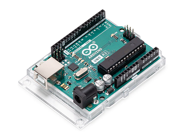 Arduino Uno Rev3: Pinout Diagram, Features and Applications
26 September 202313306
 BC817-40 NPN Transistor: Pinout, Equivalent and Datasheet
26 March 20225489
 Filter Circuit: Types, Characteristics and Principles
01 December 20218868
 Reed Relays: 10 Key Applications in Modern Electronics
04 July 20252510
 What is G.654E Fiber?
24 May 20225400
 High-Frequency Silicon Carbide MOSFETs using Resonant Gate Driver Circuits
13 March 20241760
 Comparing Popular Jumper Wires for Electronics Projects
10 July 20251578
 Innovative Changes in Leading-Edge Chip Architectures
06 September 20231645
 What is a Ceramic Filter?
10 April 20214277
 Introduction to USB Type-C
20 February 20232439
STMicroelectronics
In Stock: 6000
United States
China
Canada
Japan
Russia
Germany
United Kingdom
Singapore
Italy
Hong Kong(China)
Taiwan(China)
France
Korea
Mexico
Netherlands
Malaysia
Austria
Spain
Switzerland
Poland
Thailand
Vietnam
India
United Arab Emirates
Afghanistan
Åland Islands
Albania
Algeria
American Samoa
Andorra
Angola
Anguilla
Antigua & Barbuda
Argentina
Armenia
Aruba
Australia
Azerbaijan
Bahamas
Bahrain
Bangladesh
Barbados
Belarus
Belgium
Belize
Benin
Bermuda
Bhutan
Bolivia
Bonaire, Sint Eustatius and Saba
Bosnia & Herzegovina
Botswana
Brazil
British Indian Ocean Territory
British Virgin Islands
Brunei
Bulgaria
Burkina Faso
Burundi
Cabo Verde
Cambodia
Cameroon
Cayman Islands
Central African Republic
Chad
Chile
Christmas Island
Cocos (Keeling) Islands
Colombia
Comoros
Congo
Congo (DRC)
Cook Islands
Costa Rica
Côte d’Ivoire
Croatia
Cuba
Curaçao
Cyprus
Czechia
Denmark
Djibouti
Dominica
Dominican Republic
Ecuador
Egypt
El Salvador
Equatorial Guinea
Eritrea
Estonia
Eswatini
Ethiopia
Falkland Islands
Faroe Islands
Fiji
Finland
French Guiana
French Polynesia
Gabon
Gambia
Georgia
Ghana
Gibraltar
Greece
Greenland
Grenada
Guadeloupe
Guam
Guatemala
Guernsey
Guinea
Guinea-Bissau
Guyana
Haiti
Honduras
Hungary
Iceland
Indonesia
Iran
Iraq
Ireland
Isle of Man
Israel
Jamaica
Jersey
Jordan
Kazakhstan
Kenya
Kiribati
Kosovo
Kuwait
Kyrgyzstan
Laos
Latvia
Lebanon
Lesotho
Liberia
Libya
Liechtenstein
Lithuania
Luxembourg
Macao(China)
Madagascar
Malawi
Maldives
Mali
Malta
Marshall Islands
Martinique
Mauritania
Mauritius
Mayotte
Micronesia
Moldova
Monaco
Mongolia
Montenegro
Montserrat
Morocco
Mozambique
Myanmar
Namibia
Nauru
Nepal
New Caledonia
New Zealand
Nicaragua
Niger
Nigeria
Niue
Norfolk Island
North Korea
North Macedonia
Northern Mariana Islands
Norway
Oman
Pakistan
Palau
Palestinian Authority
Panama
Papua New Guinea
Paraguay
Peru
Philippines
Pitcairn Islands
Portugal
Puerto Rico
Qatar
Réunion
Romania
Rwanda
Samoa
San Marino
São Tomé & Príncipe
Saudi Arabia
Senegal
Serbia
Seychelles
Sierra Leone
Sint Maarten
Slovakia
Slovenia
Solomon Islands
Somalia
South Africa
South Sudan
Sri Lanka
St Helena, Ascension, Tristan da Cunha
St. Barthélemy
St. Kitts & Nevis
St. Lucia
St. Martin
St. Pierre & Miquelon
St. Vincent & Grenadines
Sudan
Suriname
Svalbard & Jan Mayen
Sweden
Syria
Tajikistan
Tanzania
Timor-Leste
Togo
Tokelau
Tonga
Trinidad & Tobago
Tunisia
Turkey
Turkmenistan
Turks & Caicos Islands
Tuvalu
U.S. Outlying Islands
U.S. Virgin Islands
Uganda
Ukraine
Uruguay
Uzbekistan
Vanuatu
Vatican City
Venezuela
Wallis & Futuna
Yemen
Zambia
Zimbabwe
![STM32F103RBT6]() STM32F103RBT6
STM32F103RBT6STMicroelectronics
![STM32F103ZET6]() STM32F103ZET6
STM32F103ZET6STMicroelectronics
![STM32H743IIT6]() STM32H743IIT6
STM32H743IIT6STMicroelectronics
![STM32F407VET6]() STM32F407VET6
STM32F407VET6STMicroelectronics
![STM32F405RGT6]() STM32F405RGT6
STM32F405RGT6STMicroelectronics
![STM32F030C8T6]() STM32F030C8T6
STM32F030C8T6STMicroelectronics
![STM32F100C8T6B]() STM32F100C8T6B
STM32F100C8T6BSTMicroelectronics
![STM32F103VBT6]() STM32F103VBT6
STM32F103VBT6STMicroelectronics
![STM8S003F3U6TR]() STM8S003F3U6TR
STM8S003F3U6TRSTMicroelectronics
![STM32F429ZIT6]() STM32F429ZIT6
STM32F429ZIT6STMicroelectronics


