
STM32C031C6T6 Datasheet Guide: Complete Beginner's Tutoria


32KB (32K x 8) FLASH ARM® Cortex®-M0+ 32-Bit Microcontroller STM32C0 Series 48-LQFP
Simplify the STM32C031C6T6 datasheet with this beginner-friendly guide. Learn pin configurations, memory layouts, and electrical specs for your projects.
Product Introduction
Reading technical datasheets for the first time can feel overwhelming. You may struggle with unfamiliar terms, dense tables, or complex diagrams. These documents often assume prior knowledge, making it harder for beginners to find the information they need. Yet, understanding the STM32C031C6T6 datasheet is essential for building reliable projects. It helps you identify pin configurations, memory layouts, and other critical details.
Users on the EEVblog Electronics Community Forum stress that for more complex microcontrollers, the datasheet serves as a crucial summary, containing essential details like pin outs and memory maps that are not always found in reference documents.
This guide will help you unlock the datasheet’s potential, breaking it down into manageable parts so you can approach your projects with confidence.
Why the STM32C031C6T6 Datasheet is Essential
Understanding the Role of Datasheets in Microcontroller Projects
Datasheets are your go-to resource when working with microcontrollers. They provide detailed technical information that helps you design, implement, and troubleshoot your projects. As microcontrollers become more advanced, their datasheets grow in complexity. This makes understanding them even more critical. For example:
Datasheets contain a wealth of information, which can initially feel overwhelming.
They are essential for verifying specifications and ensuring proper implementation.
Advanced features often require consulting the datasheet to avoid errors.
By learning to navigate the STM32C031C6T6 datasheet, you gain the confidence to make informed decisions and avoid costly mistakes in your designs.
Key Information Found in the STM32C031C6T6 Datasheet
The STM32C031C6T6 datasheet includes all the technical data you need to work with this microcontroller. Here’s a quick overview of some key specifications:
| Specification | Details |
|---|---|
| Core | ARM Cortex M0+ |
| Speed | 48 MHz |
| Flash | 32 KB |
| SRAM | 12 KB |
| Operating Voltage | 2-3.6V |
| Pins | 48 pins |
| Communication Interfaces | I2C, USART, SPI |
| ADC | 12-bit internal ADC |
This table highlights the microcontroller’s core features, such as its processing speed, memory capacity, and communication interfaces. These details help you determine if the STM32C031C6T6 meets your project’s requirements.
Overcoming Common Challenges for Beginners
As a beginner, you might find datasheets intimidating. The technical jargon, dense tables, and unfamiliar diagrams can make it hard to know where to start. To overcome these challenges:
Focus on the sections most relevant to your project, like pin configurations or electrical specifications.
Break down complex diagrams into smaller parts to understand their purpose.
Use online forums or tutorials to clarify confusing terms or concepts.
With practice, you’ll find that the STM32C031C6T6 datasheet becomes less daunting and more of a helpful guide for your microcontroller projects.
Key Sections of the STM32C031C6T6 Datasheet
Pin Configuration and Pinout Diagram
The pin configuration is one of the first things you should examine in the STM32C031C6T6 datasheet. It tells you how each pin on the microcontroller is assigned and what functions it supports. This information is critical when designing your circuit because it ensures you connect the right components to the correct pins.
The STM32C031C6T6 has 48 pins, many of which serve multiple purposes. For example, some pins can act as general-purpose input/output (GPIO) or support communication protocols like I2C, SPI, or USART. The datasheet provides a detailed pinout diagram that visually maps these functions to their respective pins.
Tip: When reading the pinout diagram, focus on the pins you plan to use in your project. Highlight them to avoid confusion later.
Here’s an example of what you might find in the pin configuration section:
Power Pins: These include VDD and VSS, which supply power to the microcontroller.
Communication Pins: Pins for I2C (SCL, SDA), SPI (MISO, MOSI, SCK), and USART (TX, RX).
Analog Pins: These connect to the ADC for analog-to-digital conversion.
Understanding the pin configuration helps you design a functional and efficient circuit.
Electrical Specifications and Operating Conditions
Electrical specifications ensure your microcontroller operates safely and efficiently. The STM32C031C6T6 datasheet provides detailed information about voltage levels, current limits, and temperature ranges.
For instance, the STM32C031C6T6 operates within a supply voltage range of 2.0V to 3.6V. Exceeding this range can damage the microcontroller. The operating temperature spans from -40°C to 125°C, making it suitable for a wide range of environments.
Here’s a summary of key electrical specifications:
| Feature | Specification |
|---|---|
| Supply Voltage | 2.0 V to 3.6 V |
| Operating Temperature | -40°C to 125°C |
| CPU Frequency | Up to 48 MHz |
| Flash Memory | Up to 32 Kbytes with protection |
| SRAM | 12 Kbytes with hardware parity check |
| ADC | 12-bit, 2.5 MSps, up to 21 channels |
| I/O Pins | Up to 45 fast I/Os |
Note: Always verify your circuit design against these specifications to prevent hardware failures.
By adhering to these electrical conditions, you can ensure the microcontroller performs reliably in your project.
Functional Block Diagram and Features
The functional block diagram provides a high-level overview of the STM32C031C6T6’s internal architecture. It shows how the microcontroller’s core, memory, peripherals, and communication interfaces interact. This diagram is especially useful when you want to understand how different features work together.
The STM32C031C6T6 is built around the ARM Cortex-M0+ core, which operates at a maximum frequency of 48 MHz. It includes 32 KB of flash memory for storing your program and 12 KB of SRAM for temporary data storage. The microcontroller also offers a variety of peripherals, such as timers, communication interfaces, and an analog-to-digital converter (ADC).
Here are some notable features:
Timers: Eight timers, including four general-purpose timers, allow you to manage time-sensitive tasks.
Communication Interfaces: Support for I2C, SPI/I2S, and USART makes it easy to connect external devices.
ADC: A 12-bit ADC with up to 21 channels enables precise analog signal measurements.
These features make the STM32C031C6T6 a versatile choice for many applications, from simple IoT devices to more complex embedded systems.
Tip: Use the functional block diagram as a roadmap to explore the microcontroller’s capabilities. It helps you identify which features you need and how to use them effectively.
By understanding the block diagram and features, you can unlock the full potential of the STM32C031C6T6 in your projects.
Memory Organization and Peripheral Details
Understanding the memory organization of the STM32C031C6T6 is crucial for optimizing your project’s performance. This microcontroller offers a well-structured memory system that supports efficient data storage and retrieval. It also includes a range of peripherals to enhance functionality. Let’s break down these details.
Memory Organization
The STM32C031C6T6 features multiple types of memory, each designed for specific tasks. Here’s an overview of its memory structure:
| Memory Type | Details |
|---|---|
| Flash Memory | Up to 2 MB, split into two banks for simultaneous read/write operations. |
| System RAM | 384 KB, includes 64 KB of Core Coupled Memory (CCM) for fast access. |
| External Memory | Built-in controller for interfacing with external high-speed RAM. |
| RAM Types Supported | SRAM, PSRAM, SDRAM, NOR/NAND Flash memory. |
Flash memory serves as the primary storage for your program code. The dual-bank design allows the microcontroller to read from one bank while writing to the other. This feature improves performance, especially in applications requiring frequent updates.
System RAM includes Core Coupled Memory (CCM), which provides faster access compared to standard RAM. This makes it ideal for tasks like real-time data processing or computation-heavy operations. If your project demands additional memory, the external memory controller lets you connect high-speed RAM. This is particularly useful for applications like video processing or large data buffering.
Tip: Use CCM for time-sensitive tasks to reduce latency and improve efficiency.
Peripheral Details
The STM32C031C6T6 comes equipped with a variety of peripherals to support diverse applications. These peripherals simplify tasks like communication, data conversion, and timing. Here are some key peripherals you’ll find in this microcontroller:
Communication Interfaces: Includes I2C, SPI, and USART for connecting external devices.
Timers: Eight timers, including general-purpose and advanced timers, for managing time-based tasks.
Analog-to-Digital Converter (ADC): A 12-bit ADC with up to 21 channels for precise analog signal measurements.
Direct Memory Access (DMA): Enables high-speed data transfer between peripherals and memory without CPU intervention.
Each peripheral is designed to handle specific tasks efficiently. For instance, the DMA controller reduces CPU workload by managing data transfers independently. This allows the processor to focus on critical operations, improving overall system performance.
Note: Always refer to the datasheet’s peripheral section to configure these features correctly for your project.
By understanding the memory organization and peripheral capabilities of the STM32C031C6T6, you can design projects that fully utilize its potential. Whether you’re building a simple IoT device or a complex embedded system, this microcontroller provides the tools you need to succeed.
How to Interpret the STM32C031C6T6 Datasheet
Prioritizing the Most Relevant Sections
When you first open the STM32C031C6T6 datasheet, the sheer volume of information can feel overwhelming. To make it manageable, focus on the sections most relevant to your project. For example:
The datasheet provides electrical specifications, which are critical for ensuring safe operation.
The reference manual details the microcontroller’s peripherals, such as timers and communication interfaces.
The programming manual, sourced from ARM, explains the CPU core and interrupt controller.
Application notes offer practical setup guidance, like configuring the ADC.
Errata documents highlight known bugs, which you should review before finalizing your PCB design.
By prioritizing these sections, you can quickly find the information you need without getting lost in less relevant details.
Decoding Tables, Charts, and Diagrams
Technical datasheets often include tables, charts, and diagrams to present complex data. Learning to interpret these visuals is essential. For instance, tables summarize specifications like voltage ranges or pin functions. Charts may illustrate performance metrics, while diagrams, such as the functional block diagram, show how components interact.
To decode these visuals effectively:
Use tools like TekScope Analysis to synchronize channels and minimize skew when analyzing waveforms.
Understand examples of skew, such as achieving 350 ps skew with matched phase cables or <50 ps skew with deskewing.
Leverage serial protocol decoding tools to analyze communication waveforms quickly.
These strategies help you extract valuable insights from the datasheet’s visuals, enhancing your understanding of the microcontroller’s capabilities.
Using the Datasheet to Troubleshoot and Solve Problems
The STM32C031C6T6 datasheet is an invaluable resource for troubleshooting. It provides detailed information about the microcontroller’s specifications, features, and limitations. When issues arise, consult the datasheet to identify potential causes and solutions.
For example, if your circuit isn’t functioning as expected, check the electrical specifications to ensure your design meets the required voltage and current levels. The datasheet also includes tips and examples that can guide you through common problems. Additionally, reviewing the errata can help you avoid known bugs that might affect your project.
By using the datasheet as a troubleshooting guide, you can resolve issues efficiently and ensure your project runs smoothly.
Applying the STM32C031C6T6 Datasheet to Your Project
Choosing the Right Microcontroller for Your Needs
Selecting the right microcontroller is the foundation of any successful project. The STM32C031C6T6 datasheet provides detailed specifications that help you evaluate whether this microcontroller aligns with your project’s requirements. For instance, it highlights the ARM Cortex-M0+ core, which operates at 48 MHz, making it suitable for low-power applications with moderate processing needs.
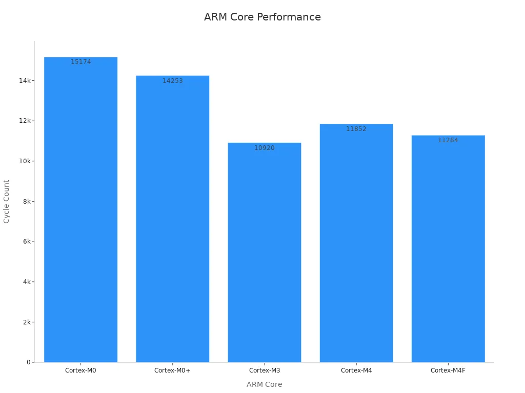
When comparing microcontrollers, benchmarks like Dhrystone offer valuable insights. Unlike MIPS, which measures raw instruction execution, Dhrystone evaluates real-world performance by counting program iteration completions per second. This benchmark helps you understand how different architectures handle similar workloads.
| ARM Core | Approximate Cycles to Complete ULPMark Active Mode |
|---|---|
| Cortex-M0 | 15,174* |
| Cortex-M0+ | 14,253 |
| Cortex-M3 | 10,920 |
| Cortex-M4 | 11,852 |
| Cortex-M4F | 11,284 |
*Estimate based on Cortex-M0+ and Cortex-M3 numbers.
The STM32C031C6T6, with its Cortex-M0+ core, offers a balance between performance and power efficiency. This makes it ideal for applications like IoT devices, where energy consumption is critical.
Tip: Always consider benchmarks, memory size, and peripheral support when choosing a microcontroller. These factors directly impact your project’s performance and scalability.
Designing Circuits with Pin Configurations
Proper pin configuration is essential for creating functional and maintainable circuits. The STM32C031C6T6 datasheet includes a detailed pinout diagram that maps each pin to its functions, such as GPIO, I2C, SPI, or USART. This information helps you design circuits that maximize the microcontroller’s capabilities.
To enhance your circuit design:
Arrange pins logically, placing inputs on the left and outputs on the right.
Ensure pin positions allow for clean, direct connections without awkward wire turns.
Highlight critical pins, such as power (VDD, VSS) and communication (TX, RX), to avoid errors during assembly.
Note: Proper pin configuration not only improves circuit readability but also simplifies debugging and future modifications.
For example, a well-organized pin layout ensures smooth data flow and reduces the risk of signal interference. This approach is particularly useful in complex designs, where multiple communication protocols operate simultaneously.
Ensuring Compatibility with Electrical Specifications
Electrical specifications define the safe operating conditions for your microcontroller. The STM32C031C6T6 datasheet specifies a supply voltage range of 2.0V to 3.6V and an operating temperature range of -40°C to 125°C. Adhering to these parameters ensures reliable performance and prevents hardware damage.
When designing your circuit, verify that all components meet these specifications. For instance:
Use a voltage regulator to maintain a stable supply voltage within the specified range.
Select capacitors and resistors rated for the same temperature range as the microcontroller.
Avoid exceeding the maximum current limits for GPIO pins to prevent damage.
Tip: Double-check your design against the datasheet before powering up your circuit. This step can save you from costly mistakes.
By ensuring compatibility with electrical specifications, you create a robust foundation for your project. This attention to detail minimizes the risk of failures and extends the lifespan of your device.
Programming and Debugging with Datasheet Guidance
The STM32C031C6T6 datasheet is an essential tool when programming and debugging your microcontroller. It provides detailed information that helps you configure the microcontroller correctly and troubleshoot issues effectively. By understanding how to use the datasheet during these stages, you can save time and avoid common mistakes.
Using the Datasheet for Programming
When programming the STM32C031C6T6, the datasheet acts as your roadmap. It outlines the microcontroller's features, registers, and memory organization, which are crucial for writing efficient code. For example, the datasheet specifies the memory map, showing where to store your program and data. This ensures that your code runs smoothly without overwriting critical areas.
To configure peripherals like timers, ADCs, or communication interfaces, you’ll need to refer to the datasheet. It provides register descriptions and bit definitions, which guide you in setting up these features. For instance, if you want to use the ADC for sensor input, the datasheet explains how to enable the ADC, select the input channel, and start a conversion.
Tip: Keep the datasheet open while coding. Cross-reference it with your Integrated Development Environment (IDE) to ensure your configurations match the microcontroller's requirements.
Debugging with Datasheet Insights
Debugging becomes much easier when you use the datasheet effectively. It helps you identify potential issues by providing detailed specifications and performance benchmarks. For example, if your circuit isn’t working as expected, the datasheet can help you verify whether your design meets the microcontroller’s electrical and timing requirements.
Here’s a table highlighting some key features and their importance in debugging:
| Feature/Specification | Description |
|---|---|
| Current Consumption | Important for assessing power efficiency in applications. |
| Oscillator Precision | Critical for timing accuracy in microcontroller operations. |
| ADC Nonlinearity | Affects the accuracy of analog-to-digital conversions, essential for debugging sensor inputs. |
If you notice unusual behavior, such as incorrect ADC readings or timing errors, check these specifications in the datasheet. For example, ADC nonlinearity might cause inaccurate sensor data. The datasheet explains how to calibrate the ADC to improve accuracy.
Practical Debugging Tips
Monitor Pin States: Use the pinout diagram to verify that each pin is configured correctly. For example, ensure that GPIO pins are set as input or output as needed.
Check Timing Parameters: Refer to the electrical specifications to confirm that your clock settings align with the microcontroller’s capabilities.
Use Debugging Tools: Combine the datasheet with debugging tools like oscilloscopes or logic analyzers. These tools help you visualize signals and compare them with the datasheet’s timing diagrams.
Note: Always review the errata document alongside the datasheet. It lists known issues and their workarounds, which can save you hours of troubleshooting.
By leveraging the STM32C031C6T6 datasheet during programming and debugging, you can create reliable and efficient projects. It not only helps you understand the microcontroller’s capabilities but also equips you to solve problems with confidence.
The STM32C031C6T6 datasheet is your key to unlocking the full potential of this microcontroller. It provides the technical foundation you need to design, troubleshoot, and optimize your projects. By practicing with the datasheet, you’ll gain confidence in navigating its sections and applying its information effectively.
Tip: Start small. Focus on one section at a time, like pin configurations or electrical specifications, to build your understanding step by step.
Continuous learning is essential. Each project you tackle will deepen your expertise, making technical documentation less intimidating and more empowering. Keep exploring, and you’ll master it in no time!
FAQ
What is the STM32C031C6T6 microcontroller best suited for?
The STM32C031C6T6 is ideal for low-power applications like IoT devices, home automation, and small embedded systems. Its ARM Cortex-M0+ core and versatile peripherals make it a great choice for projects requiring moderate processing power and efficient energy consumption.
How do I find the pin configuration for my project?
You can locate the pin configuration in the datasheet’s pinout diagram section. It maps each pin to its functions, such as GPIO or communication protocols like I2C and SPI. Highlight the pins you plan to use for better clarity.
Can I use the STM32C031C6T6 in extreme temperatures?
Yes, this microcontroller operates within a temperature range of -40°C to 125°C. This makes it suitable for both industrial and outdoor environments. Always verify your circuit components match this temperature range for reliable performance.
How do I troubleshoot issues using the datasheet?
Use the datasheet to check electrical specifications, timing parameters, and pin configurations. For example, if your ADC readings are incorrect, review the ADC calibration section. The errata document also lists known issues and solutions.
Do I need additional tools to program the STM32C031C6T6?
Yes, you’ll need an Integrated Development Environment (IDE) like STM32CubeIDE and a programmer/debugger such as ST-Link. The datasheet provides guidance on configuring peripherals and memory, which helps during programming.
Specifications
- TypeParameter
- Mounting Type
The "Mounting Type" in electronic components refers to the method used to attach or connect a component to a circuit board or other substrate, such as through-hole, surface-mount, or panel mount.
Surface Mount - Package / Case
refers to the protective housing that encases an electronic component, providing mechanical support, electrical connections, and thermal management.
48-LQFP - Supplier Device Package
The parameter "Supplier Device Package" in electronic components refers to the physical packaging or housing of the component as provided by the supplier. It specifies the form factor, dimensions, and layout of the component, which are crucial for compatibility and integration into electronic circuits and systems. The supplier device package information typically includes details such as the package type (e.g., DIP, SOP, QFN), number of pins, pitch, and overall size, allowing engineers and designers to select the appropriate component for their specific application requirements. Understanding the supplier device package is essential for proper component selection, placement, and soldering during the manufacturing process to ensure optimal performance and reliability of the electronic system.
48-LQFP (7x7) - Number of I/Os45
- PackageTray
- MfrSTMicroelectronics
- Data ConvertersA/D 21x12b SAR
- Product StatusActive
- Maximum Clock Frequency48 MHz
- Maximum Operating Temperature
the maximum body temperature at which the thermistor is designed to operate for extended periods of time with acceptable stability of its electrical characteristics.
+ 85 C - Supply Voltage-Max3.6 V
- Minimum Operating Temperature- 40 C
- Supply Voltage-Min2 V
- Mounting StylesSMD/SMT
- Interface TypeI2C
- Data RAM Size12 kB
- Operating Temperature
The operating temperature is the range of ambient temperature within which a power supply, or any other electrical equipment, operate in. This ranges from a minimum operating temperature, to a peak or maximum operating temperature, outside which, the power supply may fail.
-40°C ~ 85°C (TA) - Series
In electronic components, the "Series" refers to a group of products that share similar characteristics, designs, or functionalities, often produced by the same manufacturer. These components within a series typically have common specifications but may vary in terms of voltage, power, or packaging to meet different application needs. The series name helps identify and differentiate between various product lines within a manufacturer's catalog.
STM32C0 - Operating Supply Voltage
The voltage level by which an electrical system is designated and to which certain operating characteristics of the system are related.
2 V to 3.6 V - Oscillator Type
Wien Bridge Oscillator; RC Phase Shift Oscillator; Hartley Oscillator; Voltage Controlled Oscillator; Colpitts Oscillator; Clapp Oscillators; Crystal Oscillators; Armstrong Oscillator.
External, Internal - Speed
In electronic components, "Speed" typically refers to the rate at which data can be processed or transferred within the component. It is a measure of how quickly the component can perform its functions, such as executing instructions or transmitting signals. Speed is often specified in terms of frequency, such as clock speed in processors or data transfer rate in memory modules. Higher speed components can perform tasks more quickly, leading to improved overall performance in electronic devices. It is an important parameter to consider when designing or selecting electronic components for specific applications.
48MHz - RAM Size
RAM size refers to the amount of random access memory (RAM) available in an electronic component, such as a computer or smartphone. RAM is a type of volatile memory that stores data and instructions that are actively being used by the device's processor. The RAM size is typically measured in gigabytes (GB) and determines how much data the device can store and access quickly for processing. A larger RAM size allows for smoother multitasking, faster loading times, and better overall performance of the electronic component. It is an important factor to consider when choosing a device, especially for tasks that require a lot of memory, such as gaming, video editing, or running multiple applications simultaneously.
12K x 8 - Voltage - Supply (Vcc/Vdd)
Voltage - Supply (Vcc/Vdd) is a key parameter in electronic components that specifies the voltage level required for the proper operation of the device. It represents the power supply voltage that needs to be provided to the component for it to function correctly. This parameter is crucial as supplying the component with the correct voltage ensures that it operates within its specified limits and performance characteristics. It is typically expressed in volts (V) and is an essential consideration when designing and using electronic circuits to prevent damage and ensure reliable operation.
2V ~ 3.6V - Core Processor
The term "Core Processor" typically refers to the central processing unit (CPU) of a computer or electronic device. It is the primary component responsible for executing instructions, performing calculations, and managing data within the system. The core processor is often considered the brain of the device, as it controls the overall operation and functionality. It is crucial for determining the speed and performance capabilities of the device, as well as its ability to handle various tasks and applications efficiently. In modern devices, core processors can have multiple cores, allowing for parallel processing and improved multitasking capabilities.
ARM® Cortex®-M0+ - Peripherals
In the context of electronic components, "Peripherals" refer to devices or components that are connected to a main system or device to enhance its functionality or provide additional features. These peripherals can include input devices such as keyboards, mice, and touchscreens, as well as output devices like monitors, printers, and speakers. Other examples of peripherals include external storage devices, network adapters, and cameras. Essentially, peripherals are external devices that expand the capabilities of a main electronic system or device.
Brown-out Detect/Reset, POR, PWM, Temp Sensor, WDT - Program Memory Type
Program memory typically refers to flash memory when it is used to hold the program (instructions). Program memory may also refer to a hard drive or solid state drive (SSD). Contrast with data memory.
FLASH - Core Size
Core size in electronic components refers to the physical dimensions of the core material used in devices such as inductors and transformers. The core size directly impacts the performance characteristics of the component, including its inductance, saturation current, and frequency response. A larger core size typically allows for higher power handling capabilities and lower core losses, while a smaller core size may result in a more compact design but with limitations on power handling and efficiency. Designers must carefully select the core size based on the specific requirements of the application to achieve optimal performance and efficiency.
32-Bit - Program Memory Size
Program Memory Size refers to the amount of memory available in an electronic component, such as a microcontroller or microprocessor, that is used to store program instructions. This memory is non-volatile, meaning that the data stored in it is retained even when the power is turned off. The program memory size determines the maximum amount of code that can be stored and executed by the electronic component. It is an important parameter to consider when selecting a component for a specific application, as insufficient program memory size may limit the functionality or performance of the device.
32KB (32K x 8) - Connectivity
In electronic components, "Connectivity" refers to the ability of a component to establish and maintain connections with other components or devices within a circuit. It is a crucial parameter that determines how easily signals can be transmitted between different parts of a circuit. Connectivity can be influenced by factors such as the number of input and output ports, the type of connectors used, and the overall design of the component. Components with good connectivity are essential for ensuring reliable and efficient operation of electronic systems.
I²C, IrDA, LINbus, SPI, UART/USART - Data Bus Width
The data bus width in electronic components refers to the number of bits that can be transferred simultaneously between the processor and memory. It determines the amount of data that can be processed and transferred in a single operation. A wider data bus allows for faster data transfer speeds and improved overall performance of the electronic device. Common data bus widths include 8-bit, 16-bit, 32-bit, and 64-bit, with higher numbers indicating a larger capacity for data transfer. The data bus width is an important specification to consider when evaluating the speed and efficiency of a computer system or other electronic device.
32 bit - EEPROM Size
EEPROM Size refers to the amount of memory capacity available in an Electrically Erasable Programmable Read-Only Memory (EEPROM) chip. This parameter indicates the total storage space in bytes or bits that can be used to store data in a non-volatile manner. The EEPROM size determines the maximum amount of information that can be written, read, and erased from the memory chip. It is an important specification to consider when selecting an EEPROM for a particular application, as it directly impacts the amount of data that can be stored and accessed by the electronic component.
-
Datasheet PDF
- Datasheets :
 Introduction to Microchip PIC24EP64GP204
29 February 202477
 LP2951 Voltage Regulator: Pinout, Equivalent and Datasheet
23 October 20213031
 AD5160 Digital Potentiometer: How to Choose the Right Variant for Your Application
05 July 2025603
 SSM2164 VCA: Alternatives, Schematic, Datasheet
08 October 20214539
 MC33079DG Operational Amplifier: Datasheet, Pinout, Alternatives
03 January 20232833
 ADIS16405BMLZ: 9-Axis Inertial Sensor with Integrated Magnetometer
07 June 2025144
 STM32F429ZIT6 Microcontroller: 180MHz,144-LQFP, Pinout and Features
12 February 20223776
![PIC12F675 Microcontroller: Circuit, Pinout, and Datasheet [Video&FAQ]](https://res.utmel.com/Images/Article/be8b95c5-1756-4832-aeda-b60964c58849.png) PIC12F675 Microcontroller: Circuit, Pinout, and Datasheet [Video&FAQ]
PIC12F675 Microcontroller: Circuit, Pinout, and Datasheet [Video&FAQ]14 December 20217676
 Introduction to Reluctance Motor
08 March 20214295
 The Global Talent Pool for Major Chip Manufacturing Is Still Far From Adequate
29 April 2022537
 Introduction of 55 ADC and DAC Commonly Used Terms
02 December 20214963
 What is Mouse in Computer?
14 February 20224390
 Introduction to Optical Amplifier
27 March 20257886
 Introduction to PIC Microcontroller: Architecture, Features, and Applications
08 April 20259815
 LED Driver: Function, Types, and Application
01 September 202012660
 Rotary Switches Brand Comparison for Engineers and Buyers
11 July 20251541
STMicroelectronics
In Stock: 100000
United States
China
Canada
Japan
Russia
Germany
United Kingdom
Singapore
Italy
Hong Kong(China)
Taiwan(China)
France
Korea
Mexico
Netherlands
Malaysia
Austria
Spain
Switzerland
Poland
Thailand
Vietnam
India
United Arab Emirates
Afghanistan
Åland Islands
Albania
Algeria
American Samoa
Andorra
Angola
Anguilla
Antigua & Barbuda
Argentina
Armenia
Aruba
Australia
Azerbaijan
Bahamas
Bahrain
Bangladesh
Barbados
Belarus
Belgium
Belize
Benin
Bermuda
Bhutan
Bolivia
Bonaire, Sint Eustatius and Saba
Bosnia & Herzegovina
Botswana
Brazil
British Indian Ocean Territory
British Virgin Islands
Brunei
Bulgaria
Burkina Faso
Burundi
Cabo Verde
Cambodia
Cameroon
Cayman Islands
Central African Republic
Chad
Chile
Christmas Island
Cocos (Keeling) Islands
Colombia
Comoros
Congo
Congo (DRC)
Cook Islands
Costa Rica
Côte d’Ivoire
Croatia
Cuba
Curaçao
Cyprus
Czechia
Denmark
Djibouti
Dominica
Dominican Republic
Ecuador
Egypt
El Salvador
Equatorial Guinea
Eritrea
Estonia
Eswatini
Ethiopia
Falkland Islands
Faroe Islands
Fiji
Finland
French Guiana
French Polynesia
Gabon
Gambia
Georgia
Ghana
Gibraltar
Greece
Greenland
Grenada
Guadeloupe
Guam
Guatemala
Guernsey
Guinea
Guinea-Bissau
Guyana
Haiti
Honduras
Hungary
Iceland
Indonesia
Iran
Iraq
Ireland
Isle of Man
Israel
Jamaica
Jersey
Jordan
Kazakhstan
Kenya
Kiribati
Kosovo
Kuwait
Kyrgyzstan
Laos
Latvia
Lebanon
Lesotho
Liberia
Libya
Liechtenstein
Lithuania
Luxembourg
Macao(China)
Madagascar
Malawi
Maldives
Mali
Malta
Marshall Islands
Martinique
Mauritania
Mauritius
Mayotte
Micronesia
Moldova
Monaco
Mongolia
Montenegro
Montserrat
Morocco
Mozambique
Myanmar
Namibia
Nauru
Nepal
New Caledonia
New Zealand
Nicaragua
Niger
Nigeria
Niue
Norfolk Island
North Korea
North Macedonia
Northern Mariana Islands
Norway
Oman
Pakistan
Palau
Palestinian Authority
Panama
Papua New Guinea
Paraguay
Peru
Philippines
Pitcairn Islands
Portugal
Puerto Rico
Qatar
Réunion
Romania
Rwanda
Samoa
San Marino
São Tomé & Príncipe
Saudi Arabia
Senegal
Serbia
Seychelles
Sierra Leone
Sint Maarten
Slovakia
Slovenia
Solomon Islands
Somalia
South Africa
South Sudan
Sri Lanka
St Helena, Ascension, Tristan da Cunha
St. Barthélemy
St. Kitts & Nevis
St. Lucia
St. Martin
St. Pierre & Miquelon
St. Vincent & Grenadines
Sudan
Suriname
Svalbard & Jan Mayen
Sweden
Syria
Tajikistan
Tanzania
Timor-Leste
Togo
Tokelau
Tonga
Trinidad & Tobago
Tunisia
Turkey
Turkmenistan
Turks & Caicos Islands
Tuvalu
U.S. Outlying Islands
U.S. Virgin Islands
Uganda
Ukraine
Uruguay
Uzbekistan
Vanuatu
Vatican City
Venezuela
Wallis & Futuna
Yemen
Zambia
Zimbabwe
![STM32F103RBT6]() STM32F103RBT6
STM32F103RBT6STMicroelectronics
![STM32F103ZET6]() STM32F103ZET6
STM32F103ZET6STMicroelectronics
![STM32H743IIT6]() STM32H743IIT6
STM32H743IIT6STMicroelectronics
![STM32F407VET6]() STM32F407VET6
STM32F407VET6STMicroelectronics
![STM32F405RGT6]() STM32F405RGT6
STM32F405RGT6STMicroelectronics
![STM32F030C8T6]() STM32F030C8T6
STM32F030C8T6STMicroelectronics
![STM32F100C8T6B]() STM32F100C8T6B
STM32F100C8T6BSTMicroelectronics
![STM32F103VBT6]() STM32F103VBT6
STM32F103VBT6STMicroelectronics
![STM8S003F3U6TR]() STM8S003F3U6TR
STM8S003F3U6TRSTMicroelectronics
![STM32F429ZIT6]() STM32F429ZIT6
STM32F429ZIT6STMicroelectronics


