
AD9833: Detailed Datasheet, Pinout, and Alternatives Guide

10 Termination 0.5mm Gold Direct Digital Synthesis AD9833 10 Pin 25MHz 2.5V 10-TFSOP, 10-MSOP (0.118, 3.00mm Width)
Unit Price: $34.365852
Ext Price: $34.37


10 Termination 0.5mm Gold Direct Digital Synthesis AD9833 10 Pin 25MHz 2.5V 10-TFSOP, 10-MSOP (0.118, 3.00mm Width)
Explore the AD9833 DDS waveform generator datasheet. Get comprehensive pinout details, electrical specs, and design tips for low-power applications.
- Executive Summary: What is the AD9833?
- 1. Technical Specifications & Performance Analysis
- 2. Pinout, Package, and Configuration
- 3. Design & Integration Guide (For Engineers & Makers)
- 4. Typical Applications & Use Cases
- 5. Alternatives and Cross-Reference Guide
- 6. Frequently Asked Questions (FAQ)
- 7. Datasheets & Resources
- Specifications
- Parts with Similar Specs
- Datasheet PDF
Executive Summary: What is the AD9833?
The AD9833 is a low-power, programmable Direct Digital Synthesis (DDS) waveform generator capable of producing sine, triangular, and square wave outputs, widely used in frequency stimulus and sensing applications. It is engineered to provide a high-precision analog output from a digital reference clock.
Market Position: A highly efficient, low-cost solution for generating signals up to 12.5 MHz without the power overhead of legacy DDS chips.
Top Features:
Ultra-low power consumption of 12.65 mW at 3 V.
High precise 28-bit resolution (0.1 Hz tuning at 25 MHz clock).
Simple 3-wire SPI interface compatible with most microcontrollers.
Primary Audience: Ideal for IoT designers, test equipment engineers, and makers building portable signal generators.
Supply Status: Active. Available in standard industrial and automotive-qualified variants.

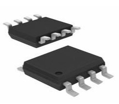
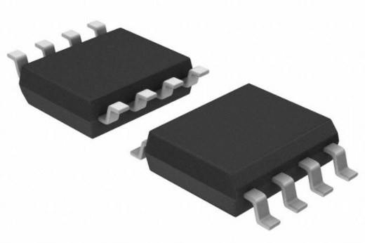
AD9833 product photo
1. Technical Specifications & Performance Analysis
1.1 Core Architecture (CPU/Logic/Power)
The AD9833 operates on the principle of Direct Digital Synthesis. It utilizes a numerical controlled oscillator (NCO) or phase accumulator to determine the frequency of the output signal. The digital phase information is converted into a digital amplitude via an on-chip SIN ROM look-up table, which is then passed through a digital-to-analog converter (DAC). This architecture allows for rapid frequency switching and fine resolution tuning, making it superior to analog oscillators in digital systems.
1.2 Key Electrical Characteristics
For portable and battery-operated designs, the AD9833 is a standout performer regarding power efficiency.
Input Voltage (VDD): 2.3 V to 5.5 V (Broad compatibility with 3.3V and 5V logic).
Power Dissipation: 12.65 mW at 3 V (Critical for thermal management in dense PCBs).
Output Frequency Range: 0 MHz to 12.5 MHz (Assuming a 25 MHz Master Clock).
Operating Temperature: -40°C to +105°C (Industrial and Automotive grade resilience).
1.3 Interfaces and Connectivity
The device communicates via a standard 3-wire SPI interface (Serial Peripheral Interface). This serial interface operates at clock rates up to 40 MHz, facilitating fast frequency modulation.
Control: Fully programmable frequency and phase registers.
Power Management: Includes a software-controlled SLEEP function to power down unused sections of the DAC, minimizing current draw when idle.

AD9833 functional block diagram
2. Pinout, Package, and Configuration
2.1 Pin Configuration Guide
The AD9833 is packed into a compact 10-lead MSOP. Below are the critical pin groupings:
Power Supply (VDD, AGND, DGND): Pins to supply 2.3 V - 5.5 V. Proper grounding is essential to minimize noise on the analog output.
Digital Interface (SDATA, SCLK, FSYNC): The SPI lines. FSYNC acts as the chip select.
Clock Input (MCLK): The reference clock (master clock) input, typically 25 MHz.
Analog Output (VOUT): The pin carrying the generated waveform.
Programming (CAP/2.5V): Internal regulator bypass or connection point.
2.2 Naming Convention & Ordering Codes
Understanding the Part Numbers:Analog Devices uses specific suffixes to denote package and qualification levels. Procurement managers should note:
BRUZ: Industrial temperature range, RoHS compliant.
WBRUZ: Automotive qualified.
REEL: Tape and Reel packaging format for automated assembly.
-EP: Enhanced Product (Defense/Aerospace specs).
2.3 Available Packages
| Package Type | Dimensions | Common Use Case |
|---|---|---|
| AD9833BRUZ | 10-lead MSOP | General consumer and industrial electronics. |
| AD9833WBRUZ | 10-lead MSOP | Automotive applications requiring AEC-Q100 compliance. |
| AD9833-EP | 10-lead MSOP | High-reliability defense and aerospace systems. |
3. Design & Integration Guide (For Engineers & Makers)
Pro Tip: While the AD9833 is versatile, its direct output is unbuffered and has a DC offset. Always verify signal conditioning circuitry before connecting to a load.
3.1 Hardware Implementation
Bypass Capacitors: Place a 100 nF ceramic capacitor and a 10 µF tantalum capacitor as close as possible to the VDD pin to decouple high-frequency noise.
PCB Layout: Separate analog and digital ground planes are recommended to prevent digital switching noise from coupling into the VOUT signal.
Thermal Management: Due to low power dissipation (12.65 mW), a heatsink is generally not required.
3.2 Common Design Challenges
Based on data from engineering forums and application notes, here are the top "Pain Points" and solutions:
Significant DC Offset
The Issue: The output signal rides on a DC level (typically approx 0.6V to 0.65V bias), which prevents it from being centered around 0V.
The Fix: Use a coupling capacitor for AC-only requirements, or implement an active op-amp circuit with offset nulling for DC-coupled applications.
Low Output Amplitude
The Issue: The peak-to-peak output voltage is roughly 0.6V pp, which is insufficient for driving substantial loads directly.
The Fix: Integrate a high-speed operational amplifier (like the AD8051) in a non-inverting gain configuration to buffer and amplify the signal.
Waveform Distortion at High Frequencies
The Issue: As frequency nears the Nyquist limit, aliasing images appear in the spectrum.
The Fix: Design a steep low-pass reconstruction filter (Elliptic or Butterworth) placed after the output to suppress clock feedthrough and images.
Complex Register Configuration
The Issue: Direct SPI bit-banging of the 16-bit control words can be error-prone.
The Fix: Use established software libraries (e.g., specific STM32 HAL drivers or Arduino libraries like
MD_AD9833) to abstract the bit manipulation.
4. Typical Applications & Use Cases
📺 Video Recommendation: AD9833 Guide
4.1 Real-World Example: Liquid Flow Measurement
In industrial flow meters, the AD9833 is utilized to generate a specific frequency excitation signal for ultrasonic or electromagnetic transducers. - The Role: The chip provides a stable, drift-free sine wave stimulus. - The Benefit: Its ability to rapidly change phase enables precise time-of-flight measurements, critical for determining flow velocity.

AD9833 application circuit schematic
5. Alternatives and Cross-Reference Guide
If the AD9833 is out of stock or does not meet specific frequency requirements, consider these alternatives:
Direct Competitors/Family:
AD9834: Similar to AD9833 but adds a comparator on-chip, useful for generating square waves with variable duty cycles.
AD9850/AD9851: Older generation, higher power consumption but often easier to find in hobbyist modules.
Different Technology:
Si5351A: A clock generator rather than a true DDS waveform generator. It produces square waves only (no native sine/triangle) but offers multiple outputs and higher frequencies.
Obsolete Parts:
MAX038: A legendary function generator chip, now obsolete. The AD9833 is a modern, digital replacement for many of its low-frequency functions.
6. Frequently Asked Questions (FAQ)
Q: What is the difference between AD9833 and AD9850? The AD9833 is significantly lower power (12.65 mW vs ~380 mW for AD9850) and smaller, but the AD9850 can handle higher clock rates in some configurations.
Q: Can AD9833 be used in automotive applications? Yes, but you must specify the AD9833WBRUZ variant which is qualified for automotive environments.
Q: Is AD9833 suitable for battery-operated devices? Absolutely. With a power-down SLEEP mode and low operating current, it is designed for portable equipment.
Q: How do I remove the DC offset from the output? You must use an external circuit, such as a series capacitor (high-pass filter) or an op-amp level shifter, as the DAC output is unipolar.
Q: What libraries are available for development? For Arduino users, the
MD_AD9833library is a popular choice that simplifies setting frequency and wave shape.
7. Datasheets & Resources
Official Datasheet: AD9833 PDF Download
Development Tools: Look for "AD9833 Breakout" or "DDS Module" for rapid prototyping.
AD9833 footprint symbol
Specifications
Parts with Similar Specs
- ImagePart NumberManufacturerPackage / CaseNumber of PinsSupply VoltageTerminal PitchMoisture Sensitivity Level (MSL)LengthTerminal PositionPin CountView Compare
![AD9833SRMZ-EP-RL7]()
AD9833SRMZ-EP-RL7
10-TFSOP, 10-MSOP (0.118, 3.00mm Width)
10
2.5 V
0.5 mm
1 (Unlimited)
3 mm
DUAL
10
![MCP4728-E/UN]()
10-TFSOP, 10-MSOP (0.118, 3.00mm Width)
10
3 V
0.5 mm
1 (Unlimited)
3 mm
DUAL
10
![AD5161BRMZ10]()
10-TFSOP, 10-MSOP (0.118, 3.00mm Width)
10
3 V
0.5 mm
1 (Unlimited)
3 mm
DUAL
10
![AD9833BRMZ]()
10-TFSOP, 10-MSOP (0.118, 3.00mm Width)
10
2.5 V
0.5 mm
1 (Unlimited)
3 mm
DUAL
10
![AD5161BRMZ100]()
10-TFSOP, 10-MSOP (0.118, 3.00mm Width)
10
5 V
0.5 mm
1 (Unlimited)
3 mm
DUAL
10


Datasheet PDF
- Datasheets :
- ConflictMineralStatement :
 LM317M Voltage Regulator: Pinout, Equivalent and Circuits
23 November 20212400
 CD4081 Quad 2 Input AND Gate IC: Pinout, Datasheet and Circuit
28 October 202110429
 xl4015 DC Buck Converter: Datasheet, Pinout and Alternatives
29 March 202220980
 TPS2553DRVR Switches: Pinout, Equivalent and Datasheet
22 October 20212849
 Exploring the Microchip PIC16C6X 8-Bit CMOS Microcontrollers
29 February 2024203
 TPS2051CDBVR Power-Distribution Switches: Layout, Pinout, and Datasheet
09 April 20221589
 ATTINY45 Microcontroller: Pinout, Specifications and Datasheet
19 October 20215045
 LM211QD Voltage Comparator Overview
14 August 2024748
 SIA's Latest Report: Status and Challenges of US Semiconductors
22 February 20231485
 What are the Types of Camera Lenses?
18 June 20212190
 NOR Flash: Working, Structure and Applications
18 November 202112609
 Trends in the Semiconductor Industry in 2022
14 February 20222544
 Revolutionizing DC Link Bus Design: Unleashing High Frequency, High-Temperature Converter Potential
11 July 20232745
 Types, Working, and Selection of DC Motor
27 March 202515215
 What is NAND Flash?
04 November 202110971
 A Beginner's Guide to the 2N5551 Transistor and Its Uses
27 May 20251875
Analog Devices Inc.
In Stock: 45
Minimum: 1 Multiples: 1
Qty
Unit Price
Ext Price
1
$34.365852
$34.37
10
$32.420615
$324.21
100
$30.585486
$3,058.55
500
$28.854232
$14,427.12
1000
$27.220974
$27,220.97
Not the price you want? Send RFQ Now and we'll contact you ASAP.
Inquire for More Quantity
![AD9834BRUZ]() AD9834BRUZ
AD9834BRUZAnalog Devices Inc.
![AD9850BRSZ]() AD9850BRSZ
AD9850BRSZAnalog Devices Inc.
![AD9832BRUZ]() AD9832BRUZ
AD9832BRUZAnalog Devices Inc.
![AD9834CRUZ]() AD9834CRUZ
AD9834CRUZAnalog Devices Inc.
![AD9833BRMZ-REEL7]() AD9833BRMZ-REEL7
AD9833BRMZ-REEL7Analog Devices Inc.
![AD9834BRUZ-REEL]() AD9834BRUZ-REEL
AD9834BRUZ-REELAnalog Devices Inc.
![AD5932YRUZ]() AD5932YRUZ
AD5932YRUZAnalog Devices Inc.
![AD9837BCPZ-RL7]() AD9837BCPZ-RL7
AD9837BCPZ-RL7Analog Devices Inc.
![AD9858BSVZ]() AD9858BSVZ
AD9858BSVZAnalog Devices Inc.
![AD9852ASVZ]() AD9852ASVZ
AD9852ASVZAnalog Devices Inc.


