

 Product
 Brand
Brand Articles
 Tools
Tools
xl4015 DC Buck Converter: Datasheet, Pinout and Alternatives

XL4015E1 datasheet pdf and Unclassified product details from XLSEMI stock available at Utmel


The XL4015 is a 180 kHz fixed frequency PWM buck (step-down) DC to DC converter, capable of driving a 5 Ampere load with high efficiency, low ripple, and excellent line and load regulation. This video will cover XL4015 features, alternatives, package, pinout, and other aspects. Please have a look.

Review of XL4015 5A 1.25 -30V DC CC Buck converter with thermal image
xl4015 Overview
The XL4015 5A CC /CV Adjustable Step-Down DC-DC Buck Converter Module is a linear module with constant voltage and constant current (CC-CV) functions and excellent performance. When it's being used as a charger. This module is stable and uses a nice chip as its core. It also has a low ripple of 50 mV.
This product is a 300 kHz fixed frequency PWM buck (step-down) DC/DC module that can drive a 0-5A (Max) Adjustable load while maintaining high efficiency, minimal ripple, and excellent line and load regulation. Use as a step-down module with built-in overcurrent protection.
The DC/DC buck module is used in applications where the input voltage is higher than the output voltage, such as batteries, power transformers, DIY adjustable regulated power supplies, and portable instrument power supplies for LCD monitors and LCD TVs. Industrial equipment buck, telecom/networking equipment, 24V car laptop power supply 12V to 3.3 V, 12V to 5V, 24V to 5V, 24V to 12V. 36V buck to 24V. and so on.
This module's output voltage and current can be adjusted. Because it is capable of CC-CV, it may also be used as a dedicated charger for Lithium Batteries (Li-Ion, LiPo ).
xl4015 CAD Models
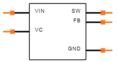
Symbol
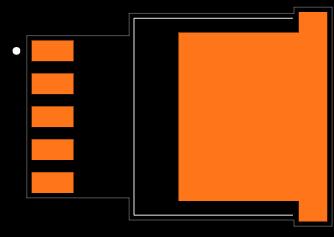
Footprint
xl4015 Features
Wide 8V to 36 V Input Voltage Range
Output Adjustable from 1.25 V to 32V
Maximum Duty Cycle 100 %
Minimum Drop Out 0.3 V
Fixed 180KHz Switching Frequency
5A Constant Output Current Capability
Internal Optimize Power MOSFET
High efficiency up to 96 %
Excellent line and load regulation
Built-in thermal shutdown function
Built-in current limit function
Built-in output short protection function
Available in TO263-5L package
xl4015 Applications
① LCD Monitor and LCD TV
② Portable instrument power supply
③ Telecom / Networking Equipment
xl4015 Function Block

xl4015 Typical Application Circuit

xl4015 Pinout and Configurations
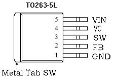
| Pin Number | Pin Name | Description |
| 1 | GND | Ground Pin. Care must be taken in layout. This pin should be placed outside of the Schottky Diode to output capacitor ground path to prevent switching current spikes from inducing voltage noise into XL4015 |
| 2 | FB | Feedback Pin (FB). Through an external resistor divider network, FB senses the output voltage and regulates it. The feedback threshold voltage is 1.25V. |
| 3 | SW | Power Switch Output Pin (SW). SW is the switch node that supplies power to the output |
| 4 | VC | Internal Voltage Regulator Bypass Capacity. In a typical system application, The VC pin connects a 1uf capacity to VIN. |
| 5 | VIN | Supply Voltage Input Pin. XL4015 operates from an 8V to 36V DC voltage. Bypass Vin to GND with a suitably large capacitor to eliminate noise on the input. |
xl4015 Dimensions
| Width | 20mm |
| Height | 10mm |
| Depth | 40mm |
| Weight | 30g |
Specifications
- TypeParameter
- Package / Case
refers to the protective housing that encases an electronic component, providing mechanical support, electrical connections, and thermal management.
TO-263-5 - Packaging
Semiconductor package is a carrier / shell used to contain and cover one or more semiconductor components or integrated circuits. The material of the shell can be metal, plastic, glass or ceramic.
Tape & Reel (TR) - Function
The parameter "Function" in electronic components refers to the specific role or purpose that the component serves within an electronic circuit. It defines how the component interacts with other elements, influences the flow of electrical signals, and contributes to the overall behavior of the system. Functions can include amplification, signal processing, switching, filtering, and energy storage, among others. Understanding the function of each component is essential for designing effective and efficient electronic systems.
Step-Down - Number of Outputs1
- Voltage - Input (Max)
Voltage - Input (Max) is a parameter in electronic components that specifies the maximum voltage that can be safely applied to the input of the component without causing damage. This parameter is crucial for ensuring the proper functioning and longevity of the component. Exceeding the maximum input voltage can lead to electrical overstress, which may result in permanent damage or failure of the component. It is important to carefully adhere to the specified maximum input voltage to prevent any potential issues and maintain the reliability of the electronic system.
36V - Output Type
The "Output Type" parameter in electronic components refers to the type of signal or data that is produced by the component as an output. This parameter specifies the nature of the output signal, such as analog or digital, and can also include details about the voltage levels, current levels, frequency, and other characteristics of the output signal. Understanding the output type of a component is crucial for ensuring compatibility with other components in a circuit or system, as well as for determining how the output signal can be utilized or processed further. In summary, the output type parameter provides essential information about the nature of the signal that is generated by the electronic component as its output.
Adjustable - Voltage - Input (Min)
Voltage - Input (Min) refers to the minimum voltage level that an electronic component requires to operate correctly. It indicates the lowest voltage that can be applied to the component while still allowing it to function as intended. If the input voltage falls below this specified minimum, the component may not perform properly or may fail to operate altogether. This parameter is critical for ensuring reliable operation and longevity of the device in electronic circuits.
8V - Output Configuration
Output Configuration in electronic components refers to the arrangement or setup of the output pins or terminals of a device. It defines how the output signals are structured and how they interact with external circuits or devices. The output configuration can determine the functionality and compatibility of the component in a circuit design. Common types of output configurations include single-ended, differential, open-drain, and push-pull configurations, each serving different purposes and applications in electronic systems. Understanding the output configuration of a component is crucial for proper integration and operation within a circuit.
Positive - Current - Output
Current - Output is a parameter in electronic components that refers to the maximum amount of current that can be delivered by the output of the component. It is a crucial specification as it determines the capability of the component to supply power to connected devices or circuits. The current output rating is typically specified in amperes (A) and is important for ensuring that the component can safely and effectively power the load it is connected to without overheating or failing. Designers and engineers must consider the current output rating when selecting components to ensure compatibility and reliable operation of the overall system.
5A - Voltage - Output (Min/Fixed)
Voltage - Output (Min/Fixed) refers to the minimum fixed output voltage level that an electronic component, such as a voltage regulator or power supply, is designed to provide under specified load conditions. This parameter ensures that the device consistently delivers a reliable voltage that meets the requirements of the connected circuits or components. It is critical for applications where stable and predictable voltage is necessary for proper operation.
1.25V - Topology
In the context of electronic components, "topology" refers to the arrangement or configuration of the components within a circuit or system. It defines how the components are connected to each other and how signals flow between them. The choice of topology can significantly impact the performance, efficiency, and functionality of the electronic system. Common topologies include series, parallel, star, mesh, and hybrid configurations, each with its own advantages and limitations. Designers carefully select the appropriate topology based on the specific requirements of the circuit to achieve the desired performance and functionality.
Buck - Frequency - Switching
"Frequency - Switching" in electronic components refers to the rate at which a device, such as a transistor or switching regulator, turns on and off during operation. This parameter is crucial in determining the efficiency and performance of power converters, oscillators, and other circuits that rely on rapid switching. Higher switching frequencies typically allow for smaller component sizes but may require more advanced design considerations to manage heat and electromagnetic interference.
180kHz - Synchronous Rectifier
Synchronous rectification is a technique for improving the efficiency of rectification by replacing diodes with actively controlled switches, usually power MOSFETs or power bipolar junction transistors (BJT).
No - Voltage - Output (Max)
Voltage - Output (Max) is a parameter that specifies the maximum voltage level that can be delivered by an electronic component, such as an integrated circuit or a power supply. It indicates the highest voltage that the component is designed to provide at its output terminal under normal operating conditions. This parameter is crucial for determining the compatibility of the component with other parts of the circuit and ensuring that the voltage requirements are met for proper functionality. Designers and engineers use this specification to ensure that the component can safely deliver the required voltage without exceeding its maximum output capability.
32V - RoHS Status
RoHS means “Restriction of Certain Hazardous Substances” in the “Hazardous Substances Directive” in electrical and electronic equipment.
RoHS Compliant
How to use xl4015?
In any case, using this module is meaningless unless you know how to use it effectively. Allow me to demonstrate the (believed to be correct) method given by my dependable foreign provider. Assume you wish to get 1A current from a 9VDC source. Connect a digital multimeter across the output connector (dialed to a suitable dc voltage range ) and adjust the V-ADJ trim pot to get a 9.0VDC result. After that, set the multimeter to the appropriate current range and adjust the I-ADJ trim pot to 1.0A. Remove the digital multimeter. connect the load, and turn it on. It's worth noting that turning one trim pot may have a minor effect on the setting of the other - this isn't a significant deal, so leave it alone!
XL4015 Major Disadvantage
Although the XL4015 module has many good characteristics that a buck converter should have, it is missing one important feature.
The module has no means of changing the output current to the load specs' chosen levels.
As a result, if you try to charge a Li-Ion battery with an XL4015 module at a rate of 2 amps, you won't be able to do so due to the aforementioned limitation.
Similarly, because the module is rated for a fixed 5 amp current, you'd be unhappy if you wished to run a 3.3 V LED at a 3 amp maximum current rate.
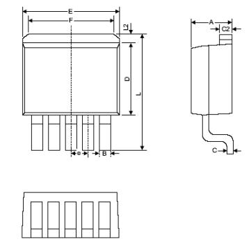
xl4015 Package
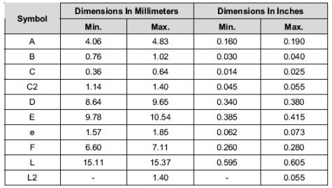
xl4015 Datasheet
xl4015 Alternatives
Trend Analysis
Parts with Similar Specs
How do I use xl4015 module?
Connect a digital multimeter across the output connector (dialed to a suitable dc voltage range) and adjust the V-ADJ trim pot to get a 9.0VDC result. After that, set the multimeter to the appropriate current range and adjust the I-ADJ trim pot to 1.0A.
What is a step down buck converter?
A buck converter, also known as a step-down converter, is a DC/DC power converter that provides voltage step down and current step up. The converter reduces the voltage when the power source has a higher voltage than Vin.
What is the difference between buck converter and buck regulator?
Buck converter converts DC into a lower voltage DC. It has a constant transformation ratio. Buck regulator is used to maintaining a constant voltage DC output for a varying voltage DC input. So the transformation ratio keeps changing here in order to keep the output voltage constant.
Can XL4015 be operated in 100℃?
Yes, its recommended operating temperature is between-40°C and 125°C.
Where is XL4015 made from?
XL4015 comes from XLSEMI.
 LM2903 Comparator: Datasheet, Schematic, and Application
07 September 20217325
 SI5351B-B I²C Clock Generator: Pinout, Features and Datasheet
22 December 20213212
 VL53L1X Laser-Ranging Sensor: Datasheet, Pinout and Schematic
29 July 202113901
 MOC3041 TRIAC Driven Optocoupler: Datasheet, Application Circuit, Pinout
23 October 202122333
 AT28BV256 EEPROMs: Pinout, Equivalent and Datasheet
20 December 2021966
 43025-0400 Dual Row 4 Circuits UL 94V-0 Low-Halogen: Datasheet, Equivalents, and Drawing
12 February 20222512
 SX1276 Transceiver: Datasheet, SX1276 vs. SX1272
09 November 202116887
 Leading Substitutes for onsemi BCP56 Transistor in 2025
19 August 2025671
 What is Wi-Fi 7?
20 August 20215760
 What is fluorescent lamp?
19 October 20214369
 What is Digital Signal Processing (DSP)?
17 March 20224969
 What is Metaverse?
09 October 20212856
 What is Safety Relay?
12 April 202525693
 Four Proximity Sensors PK, Who can Win?
08 April 20222328
 Will AI Eventually Compete With Humans for Energy Resources?
14 February 20234348
 What is Uninterruptible Power Supply (UPS)?
08 April 20215388
XLSEMI
In Stock
United States
China
Canada
Japan
Russia
Germany
United Kingdom
Singapore
Italy
Hong Kong(China)
Taiwan(China)
France
Korea
Mexico
Netherlands
Malaysia
Austria
Spain
Switzerland
Poland
Thailand
Vietnam
India
United Arab Emirates
Afghanistan
Åland Islands
Albania
Algeria
American Samoa
Andorra
Angola
Anguilla
Antigua & Barbuda
Argentina
Armenia
Aruba
Australia
Azerbaijan
Bahamas
Bahrain
Bangladesh
Barbados
Belarus
Belgium
Belize
Benin
Bermuda
Bhutan
Bolivia
Bonaire, Sint Eustatius and Saba
Bosnia & Herzegovina
Botswana
Brazil
British Indian Ocean Territory
British Virgin Islands
Brunei
Bulgaria
Burkina Faso
Burundi
Cabo Verde
Cambodia
Cameroon
Cayman Islands
Central African Republic
Chad
Chile
Christmas Island
Cocos (Keeling) Islands
Colombia
Comoros
Congo
Congo (DRC)
Cook Islands
Costa Rica
Côte d’Ivoire
Croatia
Cuba
Curaçao
Cyprus
Czechia
Denmark
Djibouti
Dominica
Dominican Republic
Ecuador
Egypt
El Salvador
Equatorial Guinea
Eritrea
Estonia
Eswatini
Ethiopia
Falkland Islands
Faroe Islands
Fiji
Finland
French Guiana
French Polynesia
Gabon
Gambia
Georgia
Ghana
Gibraltar
Greece
Greenland
Grenada
Guadeloupe
Guam
Guatemala
Guernsey
Guinea
Guinea-Bissau
Guyana
Haiti
Honduras
Hungary
Iceland
Indonesia
Iran
Iraq
Ireland
Isle of Man
Israel
Jamaica
Jersey
Jordan
Kazakhstan
Kenya
Kiribati
Kosovo
Kuwait
Kyrgyzstan
Laos
Latvia
Lebanon
Lesotho
Liberia
Libya
Liechtenstein
Lithuania
Luxembourg
Macao(China)
Madagascar
Malawi
Maldives
Mali
Malta
Marshall Islands
Martinique
Mauritania
Mauritius
Mayotte
Micronesia
Moldova
Monaco
Mongolia
Montenegro
Montserrat
Morocco
Mozambique
Myanmar
Namibia
Nauru
Nepal
New Caledonia
New Zealand
Nicaragua
Niger
Nigeria
Niue
Norfolk Island
North Korea
North Macedonia
Northern Mariana Islands
Norway
Oman
Pakistan
Palau
Palestinian Authority
Panama
Papua New Guinea
Paraguay
Peru
Philippines
Pitcairn Islands
Portugal
Puerto Rico
Qatar
Réunion
Romania
Rwanda
Samoa
San Marino
São Tomé & Príncipe
Saudi Arabia
Senegal
Serbia
Seychelles
Sierra Leone
Sint Maarten
Slovakia
Slovenia
Solomon Islands
Somalia
South Africa
South Sudan
Sri Lanka
St Helena, Ascension, Tristan da Cunha
St. Barthélemy
St. Kitts & Nevis
St. Lucia
St. Martin
St. Pierre & Miquelon
St. Vincent & Grenadines
Sudan
Suriname
Svalbard & Jan Mayen
Sweden
Syria
Tajikistan
Tanzania
Timor-Leste
Togo
Tokelau
Tonga
Trinidad & Tobago
Tunisia
Turkey
Turkmenistan
Turks & Caicos Islands
Tuvalu
U.S. Outlying Islands
U.S. Virgin Islands
Uganda
Ukraine
Uruguay
Uzbekistan
Vanuatu
Vatican City
Venezuela
Wallis & Futuna
Yemen
Zambia
Zimbabwe