Product
 Brand
Brand Articles
 Tools
Tools
Introduction to Reluctance Motor
Synchronous Reluctance Motor Intoduction Concepts
Catalog
| I. Working Principle | |
| II. Types | 1. Synchronous Reluctance Motor |
| 2. Switched Reluctance Motor | |
| III. Features | 1. Construction |
| 2. Advantage & Disadvantages | |
| IV. Applications | |
We realize that every electric motor creates mechanical motion by using fundamental electrical principles as well as electromagnetism. There are several different types of motors on the market, but choosing which one to use or which one is best for your application is challenging. A synchronous motor is one kind of motor; a reluctance motor, on the other hand, is a motor that operates on reluctance. The stator and rotor are the two most important components of this engine. A description of the reluctance motor is presented in this article.
This is a kind of advanced motor that, like a regular electric motor, has both a stator and a rotor. This motors use a direct spinning magnetic field (RPM) to synchronize the rotor's speed with the stator's RMF. These motors offer a high power density at a low cost, making them appealing in a variety of applications. The reluctance motor's operating theory is that if a magnetic material is placed inside a magnetic field, it often pulls itself into line in the least reluctance manner.
A reluctance motor's characteristics include step form, stator to rotor pole ratio, rated power or torque, torque ripple, and constant torque speed range. The reluctance motor's power factor is low, and machine performance will vary from 55 to 75 percent.
I. Working Principle of Reluctance Motor
The stator and rotor are the most important components of this engine. This is a pair of stationary components separated by an air gap. The motor construction will vary depending on the motor type, but the basic operating concept will remain the same. The stationary component, such as the stator, contains significant pole-pairs that can be created by flowing current through a cable. The rotor can be made of ferromagnetic metal and has its own set of poles.
These poles match the shapes of the stator's magnetic field. As the rotor's salient pole interacts with the stator's salient pole, the rotor is in the least reluctance place. As a result, the magnetic resistance is lower at this end. The rotor is in the greatest reluctance position as a stator pole attaches to the slots or notches of the rotor. The rotor will still drive toward the spot with the least hesitation due to energy conservation. A reluctance torque can be produced when the rotor is not completely aligned. This torque would induce rotation by dragging the rotor toward the neighboring salient stator pole.
Reluctance Motor Torque Equation
Once a ferromagnetic material is placed inside an exterior magnetic field, reluctance torque may occur, allowing the object to line up through the external magnetic field. Because of the induced torque, an inner magnetic field may form inside the object.
This torque is generated by the interaction of two fields, which twirl the target in the line's area through the magnetic field. As a result, torque is applied to the object to reduce magnetic flux reluctance. Because of the machine's saliency, this motor torque is sometimes known as Saliency torque. To run, this motor is primarily reliant on reluctance torque. As a result, the following approximation can be used to determine this torque.
These poles match the shapes of the stator's magnetic field. As the rotor's salient pole interacts with the stator's salient pole, the rotor is in the least reluctance place. As a result, the magnetic resistance is lower at this end. The rotor is in the greatest reluctance position as a stator pole attaches to the slots or notches of the rotor. The rotor will still drive toward the spot with the least hesitation due to energy conservation. A reluctance torque can be produced when the rotor is not completely aligned. This torque would induce rotation by dragging the rotor toward the neighboring salient stator pole.
II. Types
1. Synchronous Reluctance Motor
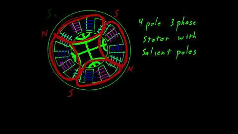
The use of a three-phase stator winding as well as a rotor to implement salient rotor poles and inner magnetic flux walls allows these motors to operate precisely at synchronous speed. In the vicinity of important poles, the rotor often performs a tweaked squirrel cage, which aids in the self-starting effect of induction. When the motor is turned on, it is driven close to synchronous speeds by induction, and then it is locked into synchronization by the reluctance torque produced by the rotor flux barriers.
2. Switched Reluctance Motor
A stepper reluctance motor with certain poles is known as a switched reluctance motor. Because of its basic configuration, this motor is less expensive to construct than an electric motor. Since it operates without a mechanical commutator, these motors are often used in explosive conditions like mines where the rotor is left idle for long periods of time. As compared to an AC induction motor operated by an inverter, these motor phase windings are electrically separated from one another, resulting in higher fault tolerance.
The so-called switched reluctance motor means that the reluctance of the magnetic circuit of each phase of the motor changes with the position of the rotor. Therefore, the magnetic field energy of the electric vehicle motor will also change with the position of the rotor, which can be converted into mechanical energy with the medium of magnetic energy. Only in this way can the power supply be cycled in phase sequence to keep the rotor rotating in one direction and output mechanical energy. Therefore, there should be a controllable switch circuit, which according to the position of the rotor to reasonably and periodically turn on and off each phase circuit, realize the rotor rotates continuously in a certain direction and output mechanical energy.
It follows the principle that the magnetic flux is always closed along the path with the largest magnetic permeability, generating magnetic pulling force to form an electromagnetic torque with a torque-reluctance nature. Therefore, its structure principle is that the reluctance of the magnetic circuit should change as much as possible when the rotor rotates, so the switched reluctance motor adopts a double salient pole structure, and the number of poles of the stator and rotor is different.
The controllable switch circuit is the converter, which forms the main power circuit together with the power supply and the motor winding. The position detector is an important characteristic component of the switched reluctance motor. It detects the position of the rotor in real-time and controls the work of the converter in an orderly and effective manner.
Features of Switched Reluctance Motor
(1) Both the stator and rotor are of the double salient pole structure
Switched reluctance motor is abbreviated as SR. It is a special type of synchronous motor. Its stator and rotor are both double salient pole structures, strong and brushless, and have a large output torque.
(2) The coil winding only needs unidirectional current
Since the coil winding of the switched reluctance motor only needs unidirectional current, it only needs a unipolar power converter to supply power, so its circuit structure is very simple.
(3) No position sensor
Early switched reluctance motor speed control systems used position sensors to detect the position of the rotor, and now there has been a switch reluctance motor speed control system without position sensors.
(4) Insufficiency of switched reluctance motor speed control system
The advantages of the switched reluctance motor speed control system are outstanding, and the application field is expanding day by day. The disadvantage is that the power converter of the switched reluctance motor speed control system outputs irregular current pulses, which may cause running noise and noise at low speeds. The torque ripple problem, which can be further improved in the control method.
III. Features of Reluctance Motor
1. Construction of Reluctance Motor
Two of the rings were short-circuited. The motor functions as a single-phase induction motor until the stator is aligned to a single-phase supply. A centrifugal transfer detaches the auxiliary winding until the motor's output approaches the maximum degree of synchronous speed. Via the main winding operation, the motor accelerates like a single-phase motor.
Once the motor speed approaches the synchronous speed, the rotor tends to connect itself in the least reluctance position, resulting in torque generation. As a result, the rotor drags in lockstep. For proper efficacy, load inertia must be kept under acceptable limits. The induction torque will vanish at synchronization, but the rotor will remain in synchronization due to the torque in synchronous reluctance.
2. Advantage & Disadvantages of Reluctance Motor
Advantages:
(1) It doesn't require DC supply.
(2) Stable characteristics
(3) Maintenance is less
(4) Less heat
(5) No magnets
(6) Speed control
Disadvantages:
1) Efficiency is less
2) Power factor is poor
3) Frequency control
4) The capacity of these motors is less to drive the loads
5) Less inertia rotor is required.
IV. Applications of Reluctance Motor
Signaling Devices
Control Devices
Automatic regulators
Recording Devices
Clocks
Tele printers
Gramophones
Analog electric meters
Electric vehicles
Power tools like drill lathes, band saws & presses
 UTMEL
UTMEL
We are the professional distributor of electronic components, providing a large variety of products to save you a lot of time, effort, and cost with our efficient self-customized service. careful order preparation fast delivery service
What are the advantages of switched reluctance motor?
Switched reluctance machines (SRMs) and their drive systems have the advantages of simple structure, low manufacturing cost, high system reliability, high efficiency, and a wide speed range, and are contenders for electric vehicle traction drives.
How does switched reluctance motor work?
Switched reluctance motors operate by switching currents in the stator windings in response to changes in the magnetic circuit formed by the rotor and stator.
How does a reluctance motor start?
It starts as an induction motor but runs with a small amount of synchronous torque. The synchronous torque is due to changes in a reluctance of the magnetic path from the stator through the rotor as the slots align.
 What is a Servo Drive?UTMEL16 June 20215746
Servo drive, also known as "servo controller" and "servo amplifier", is a kind of controller used to control servo motors. Its function is similar to that of frequency converters acting on ordinary AC motors, and it is part of the servo system. The servo drive is mainly used in high-precision positioning systems. Generally, the servo motor is controlled by three methods of position, speed, and torque to achieve high-precision transmission system positioning.
Read More What is a Switched Reluctance Motor?UTMEL09 July 20248653
Switched reluctance motor is a type of speed-regulating motor developed after DC motor and brushless DC motor. Product power levels range from several watts to hundreds of kilowatts, and are widely used in household appliances, aviation, aerospace, electronics, machinery, and electric vehicles.
Read More Types, Working, and Selection of DC MotorUTMEL27 March 202518376
A direct current motor (DC motor) is an electric motor that operates on direct current. The operation of an electric motor is based on basic electromagnetism. When a current-carrying conductor is put in an external magnetic field, it will feel a force that is equal to the current in the conductor and the frequency of the external magnetic field.
Read More Linear Induction Motor: Working Principle, Characteristics, and ApplicationsUTMEL02 March 202115666
LIM stands for Linear Induction Motor, and it is an improved version of the rotary induction motor that produces linear translational motion instead of rotating motion. Other than rotating torque, this device generates linear movement and force. By cutting a radically shaped cut in the revolving induction and thus leveling the section, the design and functionality of the linear induction motor can be demonstrated in the diagram below.
Read More Stepper Motor: Types, Working and ApplicationsUTMEL26 December 202510840
A brushless, synchronous electric motor that converts digital pulses to mechanical shaft rotation is known as a stepper motor. When operated by a sequentially switched DC power supply, the normal shaft motion is made up of discrete angular motions of approximately uniform magnitude.
Read More
Subscribe to Utmel !
![ATV61HC25N4D]() ATV61HC25N4D
ATV61HC25N4DSchneider
![ATV61HC63N4D]() ATV61HC63N4D
ATV61HC63N4DSchneider
![ATV61HC22N4D]() ATV61HC22N4D
ATV61HC22N4DSchneider
![ATV71HD37N4Z]() ATV71HD37N4Z
ATV71HD37N4ZSchneider
![2366]() 2366
2366Winchester
![EMMS-ST-28-L-SE]() EMMS-ST-28-L-SE
EMMS-ST-28-L-SEFesto
![EMMS-ST-42-S-SEB-G2]() EMMS-ST-42-S-SEB-G2
EMMS-ST-42-S-SEB-G2Festo
![EMMS-ST-57-M-SB-G2]() EMMS-ST-57-M-SB-G2
EMMS-ST-57-M-SB-G2Festo
![ILA1F571TC1F0]() ILA1F571TC1F0
ILA1F571TC1F0Schneider
![ILA1F571TB1F0]() ILA1F571TB1F0
ILA1F571TB1F0Schneider