
 Product
 Brand
Brand Articles
 Tools
Tools
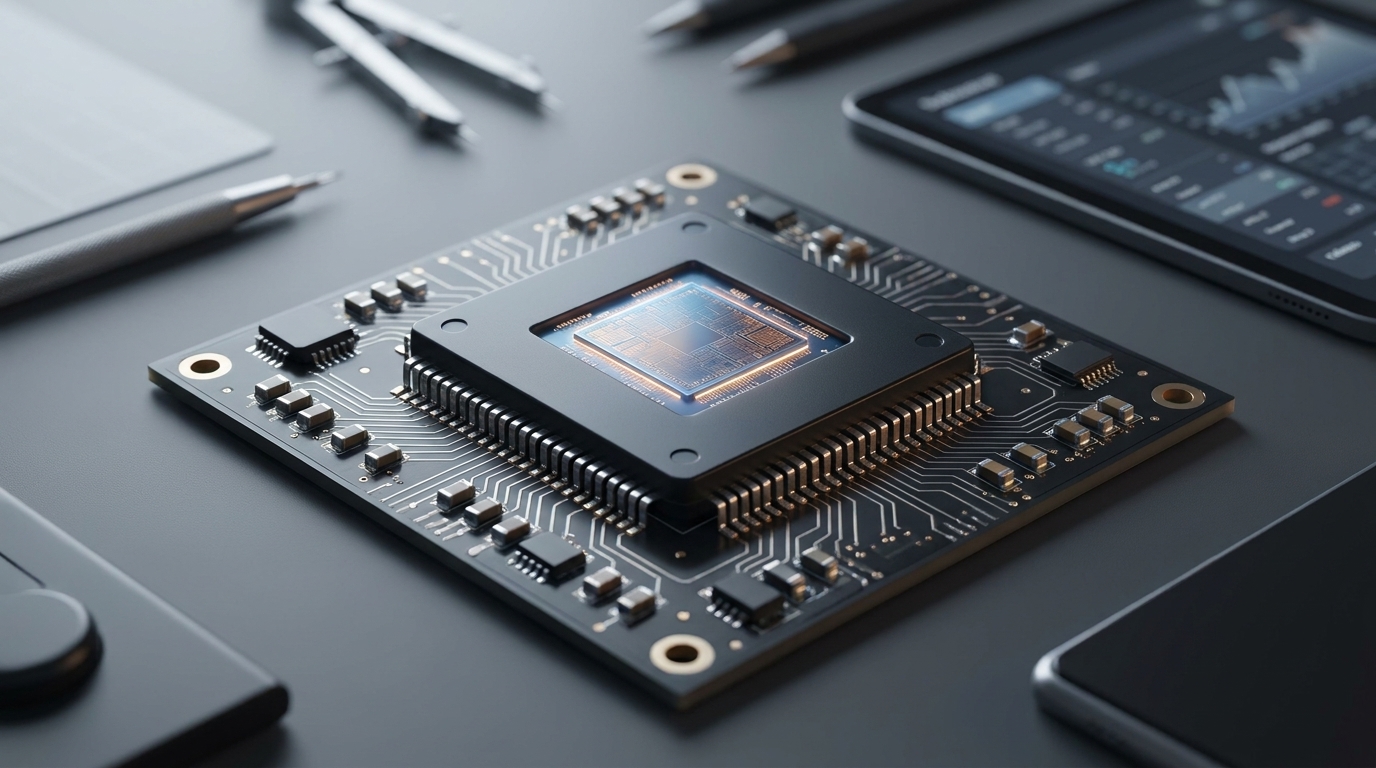
MIC4605 MOSFET Driver: Pinout, Equivalent and Datasheet

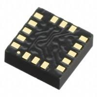
Surface Mount Tape & Reel (TR) Active Gate Drivers ICs Non-Inverting 2 108V V 10-UFDFN Exposed Pad MIC4605
Unit Price: $2.266151
Ext Price: $2.27


Surface Mount Tape & Reel (TR) Active Gate Drivers ICs Non-Inverting 2 108V V 10-UFDFN Exposed Pad MIC4605
The MIC4605 is an 85V half-bridge MOSFET driver that features adaptive dead time and shoot-through protection. The adaptive dead-time circuitry actively monitors the half-bridge outputs to minimize the time between high-side and low-side MOSFET transitions, thus maximizing power efficiency. Furthermore, Huge range of Semiconductors, Capacitors, Resistors and IcS in stock. Welcome RFQ.

Here is why MOSFET drivers are sometimes essential! || MOSFET Driver Part 1 (Driver, Bootstrapping)
MIC4605 Pinout

Pinout
MIC4605 CAD Model

PCB Symbol

PCB Footprint

3D Model
MIC4605 Overview
The MIC4605 is an 85V half-bridge MOSFET driver that features adaptive dead time and shoot-through protection. The adaptive dead-time circuitry actively monitors the half-bridge outputs to minimize the time between high-side and low-side MOSFET transitions, thus maximizing power efficiency. Shoot-through protection circuitry prevents erroneous inputs and noise from turning both MOSFETS on at the same time. The MIC4605 is available in an 8-pin SOIC package and a tiny 10-pin 2.5 mm x 2.5 mm TDFN package. Both packages have an operating junction temperature range of -40°C to +125°C. The MIC4605 also offers a wide 5.5V to 16V operating supply range to maximize system efficiency. The low 5.5V operating voltage allows longer run times in battery-powered applications. Additionally, the MIC4605 device's adjustable gate drive sets the gate drive voltage to VDD for optimal MOSFET RDS(ON), which minimizes power loss due to the MOSFET's RDS(ON).
This article provides you with a basic overview of the MIC4605 MOSFET Driver, including its pin descriptions, features and specifications, etc., to help you quickly understand what MIC4605 is.
MIC4605 Features
● 5.5V to 16V Gate Drive Supply Voltage Range
● Advanced Adaptive Dead Time
● Intelligent Shoot-Through Protection:
◆ MIC4605-1: Dual TTL inputs
◆ MIC4605-2: Single PWM input
● Enable Input for On/Off Control
● On-Chip Bootstrap Diode
● Fast 35 ns Propagation Times
● Drives 1000 pF Load with 20 ns Rise and Fall Times
● Low-Power Consumption: 135 µA Quiescent Current
● Separate High-Side and Low-Side Undervoltage Protection
● -40°C to +125°C Junction Temperature Range
● AEC-Q100 Qualified for the SOIC Package
Specifications
- TypeParameter
- Factory Lead Time8 Weeks
- Mount
In electronic components, the term "Mount" typically refers to the method or process of physically attaching or fixing a component onto a circuit board or other electronic device. This can involve soldering, adhesive bonding, or other techniques to secure the component in place. The mounting process is crucial for ensuring proper electrical connections and mechanical stability within the electronic system. Different components may have specific mounting requirements based on their size, shape, and function, and manufacturers provide guidelines for proper mounting procedures to ensure optimal performance and reliability of the electronic device.
Surface Mount - Mounting Type
The "Mounting Type" in electronic components refers to the method used to attach or connect a component to a circuit board or other substrate, such as through-hole, surface-mount, or panel mount.
Surface Mount - Package / Case
refers to the protective housing that encases an electronic component, providing mechanical support, electrical connections, and thermal management.
10-UFDFN Exposed Pad - Number of Pins10
- Supplier Device Package
The parameter "Supplier Device Package" in electronic components refers to the physical packaging or housing of the component as provided by the supplier. It specifies the form factor, dimensions, and layout of the component, which are crucial for compatibility and integration into electronic circuits and systems. The supplier device package information typically includes details such as the package type (e.g., DIP, SOP, QFN), number of pins, pitch, and overall size, allowing engineers and designers to select the appropriate component for their specific application requirements. Understanding the supplier device package is essential for proper component selection, placement, and soldering during the manufacturing process to ensure optimal performance and reliability of the electronic system.
10-TDFN (2.5x2.5) - Driver ConfigurationHalf-Bridge
- Logic voltage-VIL, VIH0.8V 2.2V
- Operating Temperature
The operating temperature is the range of ambient temperature within which a power supply, or any other electrical equipment, operate in. This ranges from a minimum operating temperature, to a peak or maximum operating temperature, outside which, the power supply may fail.
-40°C~125°C TJ - Packaging
Semiconductor package is a carrier / shell used to contain and cover one or more semiconductor components or integrated circuits. The material of the shell can be metal, plastic, glass or ceramic.
Tape & Reel (TR) - Published2016
- Part Status
Parts can have many statuses as they progress through the configuration, analysis, review, and approval stages.
Active - Moisture Sensitivity Level (MSL)
Moisture Sensitivity Level (MSL) is a standardized rating that indicates the susceptibility of electronic components, particularly semiconductors, to moisture-induced damage during storage and the soldering process, defining the allowable exposure time to ambient conditions before they require special handling or baking to prevent failures
1 (Unlimited) - Max Operating Temperature
The Maximum Operating Temperature is the maximum body temperature at which the thermistor is designed to operate for extended periods of time with acceptable stability of its electrical characteristics.
125°C - Min Operating Temperature
The "Min Operating Temperature" parameter in electronic components refers to the lowest temperature at which the component is designed to operate effectively and reliably. This parameter is crucial for ensuring the proper functioning and longevity of the component, as operating below this temperature may lead to performance issues or even damage. Manufacturers specify the minimum operating temperature to provide guidance to users on the environmental conditions in which the component can safely operate. It is important to adhere to this parameter to prevent malfunctions and ensure the overall reliability of the electronic system.
-40°C - Voltage - Supply
Voltage - Supply refers to the range of voltage levels that an electronic component or circuit is designed to operate with. It indicates the minimum and maximum supply voltage that can be applied for the device to function properly. Providing supply voltages outside this range can lead to malfunction, damage, or reduced performance. This parameter is critical for ensuring compatibility between different components in a circuit.
5.5V~16V - Base Part Number
The "Base Part Number" (BPN) in electronic components serves a similar purpose to the "Base Product Number." It refers to the primary identifier for a component that captures the essential characteristics shared by a group of similar components. The BPN provides a fundamental way to reference a family or series of components without specifying all the variations and specific details.
MIC4605 - Number of Outputs2
- Output Voltage
Output voltage is a crucial parameter in electronic components that refers to the voltage level produced by the component as a result of its operation. It represents the electrical potential difference between the output terminal of the component and a reference point, typically ground. The output voltage is a key factor in determining the performance and functionality of the component, as it dictates the level of voltage that will be delivered to the connected circuit or load. It is often specified in datasheets and technical specifications to ensure compatibility and proper functioning within a given system.
1.9V - Max Output Current
The maximum current that can be supplied to the load.
1A - Max Supply Voltage
In general, the absolute maximum common-mode voltage is VEE-0.3V and VCC+0.3V, but for products without a protection element at the VCC side, voltages up to the absolute maximum rated supply voltage (i.e. VEE+36V) can be supplied, regardless of supply voltage.
16V - Min Supply Voltage
The minimum supply voltage (V min ) is explored for sequential logic circuits by statistically simulating the impact of within-die process variations and gate-dielectric soft breakdown on data retention and hold time.
5.25V - Element Configuration
The distribution of electrons of an atom or molecule (or other physical structure) in atomic or molecular orbitals.
Single - Nominal Supply Current
Nominal current is the same as the rated current. It is the current drawn by the motor while delivering rated mechanical output at its shaft.
135μA - Input Type
Input type in electronic components refers to the classification of the signal or data that a component can accept for processing or conversion. It indicates whether the input is analog, digital, or a specific format such as TTL or CMOS. Understanding input type is crucial for ensuring compatibility between different electronic devices and circuits, as it determines how signals are interpreted and interacted with.
Non-Inverting - Rise Time
In electronics, when describing a voltage or current step function, rise time is the time taken by a signal to change from a specified low value to a specified high value.
20ns - Fall Time (Typ)
Fall Time (Typ) is a parameter used to describe the time it takes for a signal to transition from a high level to a low level in an electronic component, such as a transistor or an integrated circuit. It is typically measured in nanoseconds or microseconds and is an important characteristic that affects the performance of the component in digital circuits. A shorter fall time indicates faster switching speeds and can result in improved overall circuit performance, such as reduced power consumption and increased data transmission rates. Designers often consider the fall time specification when selecting components for their circuits to ensure proper functionality and efficiency.
20 ns - Rise / Fall Time (Typ)
The parameter "Rise / Fall Time (Typ)" in electronic components refers to the time it takes for a signal to transition from a specified low level to a specified high level (rise time) or from a high level to a low level (fall time). It is typically measured in nanoseconds or picoseconds and is an important characteristic in determining the speed and performance of a component, such as a transistor or integrated circuit. A shorter rise/fall time indicates faster signal switching and can impact the overall speed and efficiency of a circuit. Designers often consider this parameter when selecting components for high-speed applications to ensure proper signal integrity and timing.
20ns 20ns - Channel Type
In electronic components, the parameter "Channel Type" refers to the type of channel through which electrical signals or current flow within the component. This parameter is commonly associated with field-effect transistors (FETs) and other semiconductor devices. The channel type can be categorized as either N-channel or P-channel, depending on the polarity of the majority charge carriers (electrons or holes) that carry the current within the channel. N-channel devices have an electron-conducting channel, while P-channel devices have a hole-conducting channel. Understanding the channel type is crucial for proper circuit design and component selection to ensure compatibility and optimal performance.
Independent - Number of Drivers2
- Gate Type
In electronic components, the term "Gate Type" typically refers to the type of logic gate used in digital circuits. A logic gate is a fundamental building block of digital circuits that performs a specific logical operation based on the input signals it receives. Common types of logic gates include AND, OR, NOT, NAND, NOR, XOR, and XNOR gates.The Gate Type parameter specifies the specific logic function that the gate performs, such as AND, OR, or NOT. Different gate types have different truth tables that define their behavior based on the input signals. By selecting the appropriate gate type for a given application, designers can implement various logical functions and operations in digital circuits.Understanding the gate type is essential for designing and analyzing digital circuits, as it determines how the circuit processes and manipulates binary data. Choosing the right gate type is crucial for ensuring the correct functionality and performance of the digital system being designed.
N-Channel MOSFET - Current - Peak Output (Source, Sink)
The parameter "Current - Peak Output (Source, Sink)" in electronic components refers to the maximum amount of current that the component can either supply (source) or sink (absorb) under peak conditions. This parameter is important for understanding the capability of the component to handle sudden surges or spikes in current without being damaged. The peak output current is typically specified in datasheets and is crucial for designing circuits that require high current handling capabilities. It is essential to consider this parameter to ensure the component operates within its safe operating limits and to prevent potential damage or malfunction.
1A 1A - High Side Voltage - Max (Bootstrap)
The parameter "High Side Voltage - Max (Bootstrap)" in electronic components refers to the maximum voltage that can be applied to the high side of a bootstrap circuit. Bootstrap circuits are commonly used in power electronics to drive high-side MOSFETs or IGBTs efficiently. This parameter is crucial for ensuring the proper operation and reliability of the bootstrap circuit, as exceeding the maximum voltage can lead to component failure or malfunction. Designers must carefully consider this specification when selecting components and designing circuits to prevent damage and ensure optimal performance.
108V - RoHS Status
RoHS means “Restriction of Certain Hazardous Substances” in the “Hazardous Substances Directive” in electrical and electronic equipment.
ROHS3 Compliant
MIC4605 Functional Block Diagram

Top-Level Block Diagram
MIC4605 Equivalent
| Model number | Manufacturer | Description |
| MIC4605-1YM-T5 | Microchip Technology Inc | HALF BRDG BASED MOSFET DRIVER |
| MIC4605-2YM-T5 | Microchip Technology Inc | HALF BRDG BASED MOSFET DRIVER |
| MIC4605-2YM | Microchip Technology Inc | HALF BRDG BASED MOSFET DRIVER |
| MIC4605-2YM-TR | Microchip Technology Inc | HALF BRDG BASED MOSFET DRIVER |
| MIC4605-1YMT-TR | Microchip Technology Inc | HALF BRDG BASED MOSFET DRIVER |
| MIC4605-2YMT-T5 | Microchip Technology Inc | HALF BRDG BASED MOSFET DRIVER |
Parts with Similar Specs
- ImagePart NumberManufacturerPackage / CaseNumber of PinsChannel TypeNumber of DriversMax Output CurrentRise TimeMin Supply VoltageMax Supply VoltageView Compare
![MIC4605-2YMT-TR]()
MIC4605-2YMT-TR
10-UFDFN Exposed Pad
10
Independent
2
1 A
20 ns
5.25 V
16 V
![MIC4605-1YMT-TR]()
10-UFDFN Exposed Pad
10
Independent
2
1 A
20 ns
5.25 V
16 V
![MIC4604YMT-TR]()
10-UFDFN Exposed Pad
10
Independent
2
1 A
20 ns
5.25 V
16 V
![MIC4605-1YMT-T5]()
10-UFDFN Exposed Pad
10
Independent
2
1 A
20 ns
5.5 V
16 V
![MIC4604YMT-T5]()
10-UFDFN Exposed Pad
10
Independent
2
1 A
20 ns
5.5 V
16 V


MIC4605 Applications
● Fans
● Power Inverters
● High-Voltage Step-Down Regulators
● Half, Full and 3-Phase Bridge Motor Drives
● Appliances
● E-Bikes
● Automotive Applications
MIC4605 Package

Top view

Side view

Bottom view

Recommended Land Pattern
MIC4605 Manufacturer
Microchip Technology Inc. is a leading provider of microcontroller and analog semiconductors, providing low-risk product development, lower total system cost and faster time to market for thousands of diverse customer applications worldwide. Headquartered in Chandler, Arizona, Microchip offers outstanding technical support along with dependable delivery and quality.
Datasheet PDF
- PCN Assembly/Origin :
- PCN Design/Specification :
- PCN Packaging :
- ConflictMineralStatement :
- Datasheets :
What is the essential property of the MIC4605?
The MIC4605 is a noninverting, 85V half-bridge MOSFET driver designed to independently drive both high-side and low-side N-channel MOSFETs. The MIC4605 offers a wide 5.5V to 16V operating supply range with either dual TTL inputs (MIC4605-1) or a single PWM input (MIC4605-2).
Can the MIC4605 be used for input signals whose amplitude is less than the supply voltage?
The MIC4605 has a TTL-compatible input range and can be used with input signals with amplitude less than the supply voltage.
What are the advantages of the package used in MIC4605?
The MIC4605 is offered in a small 2.5 mm x 2.5 mm TDFN package for applications that are space constrained and an 8-lead SOIC package for ease of manufacturing.
 A Comprehensive Guide to LTC6993CDCB-3#TRMPBF Multivibrator IC
06 March 2024302
 A Comprehensive Guide to LTC6992CS6-4#TRPBF Programmable Timer and Oscillator
06 March 2024288
 LIS3DH Accelerometer: Datasheet, Pinout, Functionality, and Block Diagram
08 July 20218906
 MJE15030G NPN Transistor: Datasheet, Equivalent, and Pinout
28 August 20214974
 STM8S003F3P6TR: Overview, Features, and Applications
05 December 20232511
 UA741 Operational Amplifier Series: Technical Design Guide & Datasheet Analysis
19 January 20262719
 Unraveling the Zilog ZNEO™ Z16F Series Microcontroller: A Comprehensive Technical Analysis
29 February 2024496
 TPS1H200AQDGNRQ1 High-Side Switch: Diagram, Pinout, and Datasheet
30 March 20222732
 LLC Converter with Planar Matrix Transformer for High-Current-High-Power Applications
15 March 20244916
 5G Enters an Arena All Its Own: AT&T to bring 5G to AT&T Stadium
15 November 2019982
 Several Steps to Choose a Microcontroller MCU
17 June 20224729
 The 2026 Engineer’s Guide: Choosing the Right MCU for Your Next IoT & New Energy Project
30 April 2026712
 When Designing a Power Supply, How to Consider the Selection of Topology?
07 March 20224451
 LDO vs Buck Converter: Which Power Regulator Is Best For Your Application?
16 May 20257583
 How to read Resistors Color Code?
16 October 202524430
 What is LED Drive Power?
18 March 2022795
Microchip Technology
In Stock: 20780
Minimum: 1 Multiples: 1
Qty
Unit Price
Ext Price
1
$2.266151
$2.27
10
$2.137878
$21.38
100
$2.016866
$201.69
500
$1.902704
$951.35
1000
$1.795004
$1,795.00
Not the price you want? Send RFQ Now and we'll contact you ASAP.
Inquire for More Quantity
![TC4426EOA713]() TC4426EOA713
TC4426EOA713Microchip Technology
![TC4427EOA713]() TC4427EOA713
TC4427EOA713Microchip Technology
![TC4426AEOA713]() TC4426AEOA713
TC4426AEOA713Microchip Technology
![TC4422AVOA]() TC4422AVOA
TC4422AVOAMicrochip Technology
![MCP1402T-E/OT]() MCP1402T-E/OT
MCP1402T-E/OTMicrochip Technology
![MCP1416T-E/OT]() MCP1416T-E/OT
MCP1416T-E/OTMicrochip Technology
![MIC4427YMM]() MIC4427YMM
MIC4427YMMMicrochip Technology
![TC4426ACOA]() TC4426ACOA
TC4426ACOAMicrochip Technology
![TC4426EOA]() TC4426EOA
TC4426EOAMicrochip Technology
![TC4427ACOA713]() TC4427ACOA713
TC4427ACOA713Microchip Technology


