
 Product
 Brand
Brand Articles
 Tools
Tools
RF Mixer: Types, Applications, and Practical Guide
Introduction to RF Mixers
An RF mixer is a three-port electronic device that performs frequency conversion in radio frequency systems. It takes two input signals and produces an output containing various combinations of the input frequencies. As one of the most critical components in modern communication systems, RF mixers enable the translation of signals between different frequency bands, making them essential for transmitters, receivers, and test equipment.
In this comprehensive guide, we'll explore the various types of RF mixers, their working principles, practical applications, performance metrics, and provide recommendations for selecting the right mixer for your specific needs.

What You'll Learn in This Article:
Different types of RF mixers and their unique characteristics
How mixers perform frequency conversion using nonlinear principles
Performance metrics to evaluate mixer quality
Applications across wireless communications, radar, and test equipment
Practical selection guide for choosing the right RF mixer
Comparison of leading RF mixer products on the market
Troubleshooting common mixer issues
Expert recommendations and best practices
"RF mixers are the unsung heroes of modern communications, translating signals between frequency domains to enable everything from smartphones to satellite communications."
Understanding RF Mixer Basics
What Is an RF Mixer?
A mixer, as the name suggests, combines two input signals to generate their frequency sum or difference. In RF systems, mixers serve as frequency translators, taking a signal at one frequency and converting it to another while preserving the modulation information.
The primary function of an RF mixer is to change the frequency of an input signal. This is achieved by mixing the input signal with a local oscillator (LO) signal, resulting in output frequencies that are the sum and difference of the input frequencies.
The Three Ports of an RF Mixer
RF Port
The Radio Frequency port receives the input signal to be frequency-translated. In a receiver, this is where the antenna signal enters.
LO Port
The Local Oscillator port receives a stable signal from an oscillator circuit, which determines the frequency conversion result.
IF Port
The Intermediate Frequency port outputs the frequency-translated signal, typically containing both sum and difference products.
The Mathematics Behind Mixing
When two signals with frequencies fRF and fLO are input to a mixer, the output contains various frequency components, primarily:
fRF (original RF signal)
fLO (local oscillator signal)
fRF + fLO (sum product)
|fRF - fLO| (difference product)
Higher-order products (2fRF ± fLO, fRF ± 2fLO, etc.)
In most applications, a filter following the mixer selects either the sum or difference product while rejecting the others.
Key Mixer Operations
Upconversion
When a mixer is used to produce an output frequency greater than the input signal (the two frequencies are added), it's known as up-conversion. This process is commonly used in transmitters to move baseband signals up to RF.
Downconversion
When a mixer is used to produce an output frequency lower than the input signal (the difference between frequencies), it's known as down-conversion. This is fundamental in receivers to move RF signals down to baseband.
Video: Detailed explanation of RF mixer basics and frequency conversion principles
Types of RF Mixers
RF mixers come in various configurations, each with unique characteristics that make them suitable for specific applications. Understanding the different types is essential for selecting the right mixer for your needs.
Passive Mixers: Single, Double, and Triple Balanced
Single-Balanced Mixers
These mixers use a single diode or transistor pair. They offer simplicity but provide only moderate isolation between ports.
Key Characteristics:
Simplest design
Limited port isolation
Good for cost-sensitive applications
Higher spurious responses
Double-Balanced Mixers
Using a ring of four diodes or a quad transistor arrangement, these mixers provide better isolation and spurious signal rejection.
Key Characteristics:
Excellent isolation between ports
Good balance of performance
Reduced even-order harmonics
Widely used in commercial systems
Triple-Balanced Mixers
The most complex design using multiple diode rings, offering superior isolation and intermodulation performance.
Key Characteristics:
Highest isolation performance
Complex architecture
Lower intermodulation distortion
Used in high-performance applications
Advantages of Passive Mixers
Wide bandwidth - Excellent performance across large frequency ranges
High dynamic range - Better handling of strong signals without distortion
Low noise figure - Often equal to the mixer's conversion loss
Good port-to-port isolation - Especially in double and triple-balanced designs
No DC power required - Simplifies integration in some systems
Limitations of Passive Mixers
High LO drive requirements - Typically 13-20 dBm, which can be challenging in some applications
Conversion loss - Output signal power is lower than input power
Limited low-frequency operation - Performance may degrade at very low frequencies

Figure: Double-Balanced Mixer Circuit Diagram
I/Q Image Reject (IRM) Mixer
I/Q mixers are specialized passive mixers that provide the ability to filter out unwanted image signals internally. They consist of two identical mixers with phase shifters that create output signals 90° out of phase with each other.
How I/Q Mixers Work
I/Q mixers split the LO signal into two paths with a 90° phase shift. This allows the mixer to generate only the desired sideband while suppressing the unwanted one. When used as downconverters, they're called Image Reject Mixers (IRMs), and when used as upconverters, they're known as Single Sideband Mixers (SSBs).
Key Advantages
Inherent image rejection (typically 20-40 dB)
No need for expensive external filtering
Good amplitude and phase matching
Excellent for applications requiring sideband suppression

Figure: I/Q Mixer Block Diagram and Image Rejection Frequency Domain Diagram
Limitations of I/Q Mixers
Higher LO drive requirements - Typically requires about 3 dB more LO power than standard double-balanced mixers
Sensitivity to phase/amplitude balance - Performance depends on precise 90° phase shifts and amplitude matching
More complex to implement - Requires careful design to achieve specified image rejection
I/Q mixers are particularly valuable in microwave point-to-point backhaul communications, test and measurement equipment, and military applications where sideband suppression is critical without adding complex external filtering.
Active Mixers
Active mixers incorporate gain stages and typically use transistors in their design. Most common active mixers are based on Gilbert cell multiplier configurations, which provide conversion gain rather than loss.
Types of Active Mixers
The two basic varieties are single-balanced and double-balanced active mixers (Gilbert cell mixers). They include built-in gain blocks at the RF output and LO port, offering advantages in many applications.
Key Advantages
Conversion gain - Amplifies the signal rather than attenuating it
Low LO drive requirements - Typically around 0 dBm versus 13-20 dBm for passive mixers
Integrated LO doubler - Some include frequency multiplication functionality
High integration and small size - Good for space-constrained designs
Good port isolation - Especially in well-designed Gilbert cell configurations

Figure: Double-balanced active mixer schematic based on Gilbert cell
Limitations of Active Mixers
Higher noise figure - Active components contribute additional noise
Lower linearity - Generally poorer distortion performance compared to passive mixers
DC power consumption - Requires external power supply
Limited dynamic range - More susceptible to overload from strong signals
Active mixers are commonly used in communications and defense applications where low LO drive and integrated conversion gain are crucial. They're also frequently employed in low-end instrumentation or as the third or final stage mixer in the IF portion of test and measurement equipment.
Integrated Frequency Conversion Mixer
Integrated frequency converters combine multiple functional components into a single package or chip, forming a subsystem that simplifies the final system design for the customer.
Components Often Integrated
Mixers
Phase-locked loops (PLLs)
Voltage-controlled oscillators (VCOs)
Frequency multipliers
Gain blocks
Detectors
Filters
Amplifiers
Control interfaces
Key Benefits
Reduced Size
Single package solutions take up less PCB space than discrete components
Fewer Components
Reduces bill of materials and simplifies sourcing
Simplified Design Architecture
Less time spent on interfacing between components
Faster Time to Market
Pre-integrated solutions reduce development cycles

Figure: Functional block diagram of an integrated frequency translation mixer
Integrated frequency converters are ideal for applications where space is limited, development time is critical, or when consistent performance across many units is required. They've become increasingly popular in modern wireless systems, software-defined radios, and small form factor communication devices.
Applications of RF Mixers
RF mixers are essential components in numerous wireless systems and communication devices. Their frequency translation capabilities make them crucial in both transmitters and receivers, as well as in test and measurement equipment.
Communications Systems
Superheterodyne Receivers
The most common receiver architecture uses mixers to convert RF signals to a fixed intermediate frequency (IF) where filtering and amplification are optimized.
Transmitters
Mixers upconvert baseband or IF signals to RF for transmission through antennas.
Common Communication Applications:
Cellular networks (GSM, CDMA, LTE, 5G)
Satellite communications
Wireless local area networks (WLAN)
Bluetooth devices
Two-way radios
Broadcasting equipment
Radar Systems
Radar Receivers
Mixers convert received radar echoes to lower frequencies for processing and analysis.
Doppler Processing
Special mixer configurations extract Doppler shift information to determine target velocity.
Radar Applications:
Military surveillance and targeting
Weather forecasting
Air traffic control
Automotive collision avoidance
Ground penetrating radar
Marine navigation
Test and Measurement
Spectrum Analyzers
Mixers are key components in translating input frequencies to a range that can be analyzed.
Signal Generators
Used to create precise frequency outputs by mixing and filtering reference signals.
Network Analyzers
Employ mixers to convert signals for phase and amplitude comparison.
Common Applications:
RF system characterization
Component testing
Research and development
Production testing
Specialized Applications
Software Defined Radio (SDR)
Mixers convert between RF and baseband/IF for digital processing in flexible radio architectures.
Medical Imaging
RF mixers are used in MRI systems and ultrasound equipment for signal processing.
Scientific Research
Applications in radio astronomy, particle accelerators, and quantum computing.
Additional Applications:
Electronic warfare systems
RFID readers
IoT wireless devices
GPS receivers
Real-World Application Example: Cellular Phone RF Front End
In a modern smartphone, RF mixers are critical components in the RF transceiver section. The RF chip is responsible for RF transceiver functions, frequency synthesis, and power amplification.
Receiver Path:
The antenna receives electromagnetic waves from cell towers
Signals pass through the antenna switch to the receiver path
Low-noise amplifiers boost the weak RF signal
RF mixers downconvert the signal to a lower IF frequency
The signal is filtered, amplified, and sent to the baseband processor
Transmitter Path:
Baseband processor sends data to be transmitted
Modulator inside the RF chip processes the signal
RF mixers upconvert the signal to the proper transmission frequency
Power amplifiers boost the signal to the needed transmission power
The signal passes through the antenna switch to the antenna

Block diagram of a transmitter circuit in a cellular device showing the RF mixer's role
RF Mixer Performance Metrics
To properly evaluate and select RF mixers for specific applications, it's essential to understand their key performance parameters and specifications. These metrics determine how well a mixer will perform in your system.
| Parameter | Description | Typical Values | Importance |
|---|---|---|---|
| Conversion Loss/Gain | The ratio of RF input power to IF output power (loss for passive, gain for active mixers) | 5-8 dB loss (passive) 5-15 dB gain (active) | Determines system gain budget and sensitivity |
| Noise Figure | The degradation in signal-to-noise ratio caused by the mixer | 5-10 dB (passive) 10-15 dB (active) | Critical for receiver sensitivity and weak signal detection |
| 1dB Compression Point (P1dB) | RF input power at which the conversion gain decreases by 1 dB from its small-signal value | 0 to +20 dBm | Indicates linearity and ability to handle strong signals |
| Third-Order Intercept Point (IP3) | Theoretical point where third-order intermodulation products equal the fundamental output | +10 to +30 dBm | Key linearity metric, especially for handling multiple signals |
| Port-to-Port Isolation | The attenuation of signals between mixer ports (LO-RF, LO-IF, RF-IF) | 20-60 dB | Prevents signal leakage and unwanted interference |
| Frequency Range | The operational bandwidth of RF, LO, and IF ports | Varies widely by design | Must match system frequency requirements |
| LO Drive Level | The power level required at the LO port for optimal performance | +7 to +27 dBm (passive) -10 to +3 dBm (active) | Determines LO amplifier requirements |
| VSWR (Voltage Standing Wave Ratio) | Measure of the impedance match at each port | 1.5:1 to 3:1 | Affects signal reflection and power transfer |
Understanding Conversion Loss/Gain
Conversion loss (or gain for active mixers) is one of the most fundamental parameters of a mixer. It measures how efficiently the mixer transfers power from the RF input to the IF output.
For Passive Mixers:
Conversion Loss = PRF_input - PIF_output (in dB)
A lower conversion loss indicates better performance. For example, if a mixer has 6 dB of conversion loss and the input RF power is 0 dBm, the IF output power will be -6 dBm.
For Active Mixers:
Conversion Gain = PIF_output - PRF_input (in dB)
Active mixers provide gain rather than loss, amplifying the signal during the frequency conversion process.
Noise Figure
Noise figure measures how much the mixer degrades the signal-to-noise ratio of the signal passing through it.
For passive mixers, the noise figure is approximately equal to the conversion loss under matched conditions. For active mixers, the noise figure is typically higher due to the additional noise from active components.
Why It Matters:
In receiver applications, the mixer's noise figure directly impacts the system's ability to detect weak signals. A lower noise figure means better sensitivity and performance in low-signal environments.
Linearity Metrics (P1dB and IP3)
Linearity describes how well a mixer maintains proportional output as input power increases. Two key metrics are:
P1dB (1dB Compression Point): The input power where the output is 1dB less than the ideal linear response
IP3 (Third-Order Intercept Point): A theoretical point indicating the mixer's ability to suppress intermodulation products
Why It Matters:
Higher linearity allows the mixer to handle multiple strong signals without generating unwanted intermodulation products that can interfere with desired signals.
Port-to-Port Isolation
Port-to-port isolation measures how well the mixer prevents signals from leaking between its ports. Good isolation is crucial for system performance and preventing unwanted interactions.
LO-RF Isolation
Prevents the LO signal from appearing at the RF port, which could radiate from the antenna or interfere with preceding stages.
LO-IF Isolation
Prevents the LO signal from appearing at the IF output, which could overload subsequent stages or create unwanted responses.
RF-IF Isolation
Prevents the RF signal from directly leaking to the IF output without proper frequency conversion.
Double-balanced and triple-balanced mixers typically offer better isolation performance than single-balanced designs. For applications where isolation is critical, such as in high-performance receivers or systems with high-power transmitters nearby, this parameter becomes especially important.
Recommended Equipment for Mixer Performance Testing
Essential Equipment:
Signal generators for RF and LO inputs
Spectrum analyzer for output measurement
Power meters for accurate level setting
Filters for isolating desired products
Vector network analyzer for impedance measurements
Measurement Best Practices:
Maintain proper impedance matching at all ports
Use appropriate filtering to isolate the desired output product
Set LO power to the manufacturer's recommended level
Account for cable and connector losses in measurements
Verify measurements with multiple methods when possible
Top RF Mixer Products Comparison
When selecting an RF mixer for your application, it's helpful to compare the specifications and features of leading products on the market. Below, we examine three popular RF mixers with different characteristics to suit various applications.
Analog Devices ADL5350ACPZ-R7
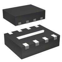 The ADL5350 is a high-performance, wide bandwidth mixer designed for cellular, CDMA, and GSM applications operating in the 750 MHz to 4 GHz range. It offers excellent linearity and noise performance in a compact package.
Key Specifications:
Frequency Range: 750 MHz - 4 GHz
Noise Figure: 6.5 dB
P1dB: 19.8 dBm
Package: 8-VFDFN Exposed Pad
Operating Temperature: -40°C to +85°C
Electrical Characteristics:
Supply Voltage: 2.7V - 3.5V
Current Consumption: 16.5 mA
Power Dissipation: 324 mW
Number of Mixers: 1
Ideal For:
Cellular base stations
Wireless infrastructure
Test and measurement equipment
High-performance receivers
Pros & Cons:
Pros:
Excellent linearity
Wide bandwidth
Small form factor
Cons:
Higher cost
Requires proper heatsinking
Mini-Circuits MAC-42+

The MAC-42+ is a versatile double-balanced mixer designed for cellular, PCN, radar, and WCDMA applications. It provides excellent isolation and conversion performance across a wide frequency range from 1 GHz to 4.2 GHz.
Key Specifications:
Frequency Range: 1 GHz - 4.2 GHz
Conversion Loss: 6.5 dB typical
LO-RF Isolation: 35 dB typical
Package: 10-SMD, No Lead
LO Power: +13 dBm (recommended)
Electrical Characteristics:
Passive design (no DC power required)
Current Consumption: 40 mA (when driven)
Input IP3: +18 dBm typical
Number of Mixers: 1
Ideal For:
Wireless base stations
Point-to-point communications
Radar systems
General-purpose RF applications
Pros & Cons:
Pros:
Excellent isolation
No DC power required
Good intermodulation performance
Cons:
Requires high LO drive level
Conversion loss (vs. gain)
Skyworks SKY73021-11
 The SKY73021-11 is a high-performance double-balanced mixer designed for CDMA, EDGE, GSM, and WCDMA applications. It operates in the 1.7 GHz to 2.2 GHz range and features two mixers in a single package for versatility.
Key Specifications:
Frequency Range: 1.7 GHz - 2.2 GHz
Noise Figure: 9.6 dB
Gain: 6 dB
Package: 36-SMD Module
Characteristic Impedance: 50 Ohm
Electrical Characteristics:
Supply Voltage: 5V
Current Consumption: 380 mA
Operating Temperature: -40°C to +85°C
Number of Mixers: 2
Ideal For:
Mobile communication devices
Wireless base stations
Dual-channel applications
WCDMA/UMTS systems
Pros & Cons:
Pros:
Dual mixer functionality
Good isolation
Positive gain (active design)
Cons:
Higher power consumption
Narrower bandwidth
Discontinued (legacy support)
Comparative Analysis
| Feature | ADL5350ACPZ-R7 | MAC-42+ | SKY73021-11 |
|---|---|---|---|
| Type | Active Mixer | Passive Double-Balanced | Double-Balanced Active |
| Frequency Range | 750 MHz - 4 GHz | 1 GHz - 4.2 GHz | 1.7 GHz - 2.2 GHz |
| Noise Figure | 6.5 dB | ~6.5 dB (equal to conversion loss) | 9.6 dB |
| Gain/Loss | Gain (value not specified) | 6.5 dB loss | 6 dB gain |
| Supply Voltage | 2.7V - 3.5V | None (Passive) | 5V |
| Current Consumption | 16.5 mA | 0 mA (Passive) | 380 mA |
| Package | 8-VFDFN | 10-SMD | 36-SMD Module |
| Number of Mixers | 1 | 1 | 2 |
| Best For | Wide bandwidth applications | Low power consumption | Dual-channel systems |
Selection Guidelines
When selecting an RF mixer for your application, consider these key factors:
Technical Considerations:
Frequency Range: Must cover your operating frequencies
Mixer Type: Active vs. passive based on system requirements
Linearity Requirements: P1dB and IP3 specifications
Power Budget: Consider DC power availability
Noise Requirements: Critical for receiver applications
Practical Considerations:
Cost: Budget constraints for your project
Availability: Supply chain considerations
Form Factor: Space constraints in your design
Reliability: Environmental conditions and lifetime requirements
Support: Manufacturer documentation and resources
Checklist of Options:
For highest performance: Consider Analog Devices ADL5350 or similar high-performance mixers
For lowest power consumption: Passive mixers like Mini-Circuits MAC series offer zero DC power consumption
For multi-channel applications: Look for dual-mixer solutions like the Skyworks SKY73021 series
For budget-sensitive projects: Simpler single-balanced designs may offer adequate performance at lower cost
For miniaturization: Look for highly integrated solutions with multiple functions in one package
Troubleshooting Common RF Mixer Issues
Even the best-designed RF systems can encounter mixer-related issues. Understanding common problems and their solutions can help you quickly diagnose and resolve issues in your RF designs.
Poor Conversion Performance
Symptoms:
Higher conversion loss than expected
Weak or no output signal
Inconsistent output levels
Possible Causes and Solutions:
Incorrect LO Power: Verify the LO is at the recommended power level for optimal conversion
Poor Impedance Matching: Use proper matching networks at all ports
Frequency Range Issues: Ensure the mixer is rated for your operating frequencies
LO Signal Quality: Check for phase noise or stability issues in your local oscillator
Unwanted Signal Feedthrough
Symptoms:
LO signal appears at RF or IF ports
Input signal leaking directly to output
Poor isolation performance
Possible Causes and Solutions:
Inadequate Mixer Balance: Use a more balanced mixer topology (double or triple-balanced)
Poor PCB Layout: Improve isolation between ports through better layout practices
Insufficient Shielding: Add proper RF shielding between stages
Port Termination Issues: Ensure proper termination of all mixer ports, especially at image frequencies
Intermodulation Distortion
Symptoms:
Unwanted signals appearing at output
Distortion with multiple input signals
Degraded signal quality
Possible Causes and Solutions:
Input Signal Too Strong: Reduce input power or add attenuation
Mixer Linearity Limitations: Choose a mixer with better IP3 specifications
Power Supply Issues: Ensure clean, well-regulated power supply (for active mixers)
Input Filtering: Add bandpass filtering before the mixer to limit out-of-band signals
Temperature-Related Performance Variations
Symptoms:
Performance changes as device warms up
Drift in conversion loss over time
Unreliable operation in extreme temperatures
Possible Causes and Solutions:
Thermal Considerations: Improve heatsinking for active mixers
Component Selection: Choose mixers rated for your temperature range
Thermal Compensation: Consider automatic level control circuits
Stabilization Time: Allow sufficient warm-up time for sensitive applications
Image Frequency Issues
Symptoms:
Unwanted signals appearing at the IF
Response to signals at image frequencies
Interference issues
Possible Causes and Solutions:
Image Rejection: Use an image reject mixer (IRM) for better image suppression
Pre-Selection Filtering: Add RF filtering before the mixer to reject image frequencies
IF Selection: Choose an IF frequency that places the image far from bands of interest
Multiple Conversion Stages: Consider using multiple mixing stages for better image rejection
Repeated Mixer Failures
Symptoms:
Mixer stops working after a period of operation
Permanent damage to mixer components
Recurring failures after replacement
Possible Causes and Solutions:
ESD Damage: Implement proper ESD protection during handling
Excessive RF Input: Add limiters to prevent damage from strong signals
DC Supply Issues: Check for transients or improper biasing
Overheating: Improve thermal management and air flow
Out-of-Spec Operation: Review datasheet absolute maximum ratings
Real User Experience Stories
Case Study: Solving Interference Issues in a Wireless Base Station
"We were experiencing intermittent interference in our wireless base station receiver. After troubleshooting, we discovered that our passive mixer's LO-RF isolation was insufficient, allowing the LO signal to leak back to our antenna. By replacing it with a double-balanced mixer with better isolation characteristics, we eliminated the problem completely."
— RF Engineer, Telecommunications Company
Case Study: Overcoming Power Budget Limitations in a Portable Device
"Our portable medical device had strict power constraints, but we needed good RF performance. Initially, we used an active mixer, but battery life was suffering. Switching to a passive mixer with an efficient LO buffer amplifier reduced our power consumption by 70% while maintaining acceptable performance. The key was finding the right balance between LO drive requirements and power budget."
— Design Engineer, Medical Devices Manufacturer
Common Misconceptions About RF Mixers
Misconception: More Expensive Mixers Are Always Better
The Reality: The "best" mixer depends entirely on your application requirements. In some cases, a simple passive mixer may outperform an expensive active mixer, especially in terms of linearity and intermodulation performance.
Better Approach: Focus on selecting a mixer whose specifications match your specific needs rather than choosing based solely on price or brand reputation.
Misconception: Active Mixers Are Always Superior to Passive Mixers
The Reality: While active mixers provide gain and require lower LO drive levels, passive mixers often have better linearity, lower noise figures, and broader frequency ranges.
Better Approach: Understand the trade-offs between active and passive mixers and select based on your system's specific requirements for power, noise, and linearity.
Misconception: Mixers Are Plug-and-Play Components
The Reality: RF mixers require careful attention to impedance matching, port termination, and power levels to achieve optimal performance.
Better Approach: Treat the mixer and its surrounding circuitry as a system, paying special attention to proper matching networks, filtering, and bias conditions.
Misconception: All Mixers Have Similar Performance
The Reality: Different mixer topologies (single-balanced, double-balanced, etc.) have dramatically different performance characteristics in terms of isolation, spurious responses, and intermodulation.
Better Approach: Choose the mixer topology that best addresses your application's critical requirements, whether that's isolation, linearity, or another parameter.
Frequently Asked Questions About RF Mixers
Here are answers to some of the most common questions about RF mixers and their applications.
What is the difference between active and passive RF mixers?
Active mixers incorporate gain stages using transistors and require DC power to operate. They typically provide conversion gain (amplification) rather than loss and need lower LO drive levels. Passive mixers, on the other hand, use components like diodes that don't require DC power. They exhibit conversion loss but often provide better linearity, lower noise figures, and can handle higher power levels. Active mixers are preferred when system gain is critical, while passive mixers excel in applications requiring high linearity and lower power consumption.
How do I select the right LO power level for my mixer?
The optimal LO power level is typically specified in the mixer's datasheet and is critical for achieving the best performance. For passive mixers, insufficient LO power leads to higher conversion loss and poorer linearity, while excessive LO power can cause saturation and increased spurious responses. Most passive mixers require +7 to +17 dBm LO power, while active mixers typically need -10 to +3 dBm. Always check the datasheet for the recommended LO drive level that provides the best balance of conversion loss/gain, linearity, and spurious performance.
What is image rejection and why is it important in receiver designs?
Image rejection refers to a receiver's ability to suppress unwanted signals at the "image frequency" - a frequency that, when mixed with the LO, produces the same IF as the desired signal. For example, if you're receiving a signal at 100 MHz using a 90 MHz LO to produce a 10 MHz IF, a signal at 80 MHz would also produce a 10 MHz IF (90-80=10). This 80 MHz signal is the "image" and could interfere with reception of the desired 100 MHz signal.
Image rejection is crucial because without it, receivers would be susceptible to interference from signals at the image frequency. Techniques for image rejection include using pre-selection filters before the mixer, image-reject mixer architectures, or selecting a high enough IF so that the image frequency can be easily filtered.
Can I use an RF mixer for audio applications?
While RF mixers are designed for radio frequency applications, some types can be used for audio mixing, particularly for effects like ring modulation in music synthesizers. However, traditional RF mixers may not be optimal for audio applications due to their frequency response characteristics, impedance levels, and typical operating frequency ranges.
For audio applications, dedicated audio mixers or analog multiplier ICs are typically more appropriate. They're designed with the right impedance levels, noise characteristics, and frequency response for audio signals. If you do need to use an RF mixer for audio, look for ones that can operate at low frequencies and consider impedance matching networks to interface with audio equipment.
How do I properly terminate the unused port of a mixer?
Proper termination of unused mixer ports is critical for achieving optimal performance. The general rule is to terminate any unused port with the mixer's characteristic impedance (typically 50 ohms for RF systems) across the frequency range of interest.
For RF and LO ports, use a broadband 50-ohm termination that covers the operating frequency range. For IF ports in downconversion applications, ensure the termination covers from DC to the highest expected IF frequency. Improper termination can lead to increased conversion loss, poor isolation, and unwanted reflections that degrade overall performance.
In sensitive applications, consider using terminations that present the correct impedance not just at the fundamental frequencies but also at harmonic and image frequencies to minimize spurious responses.
Conclusion: Making the Right RF Mixer Choice
RF mixers are fundamental components in modern wireless communication systems, playing a critical role in frequency translation for both transmitters and receivers. As we've explored throughout this article, the selection of the appropriate mixer type and model requires a careful assessment of your application's specific requirements and constraints.
Key Takeaways
Mixer Variety: From simple single-balanced designs to complex triple-balanced and image-reject architectures, each mixer type offers unique advantages for specific applications.
Performance Trade-offs: Consider the balance between conversion loss/gain, linearity, noise figure, port isolation, and power requirements when selecting a mixer.
Active vs. Passive: Active mixers offer gain and low LO drive requirements at the expense of linearity and power consumption, while passive mixers provide better linearity and no DC power requirement but need higher LO drive levels.
Application-Specific Selection: The "best" mixer depends entirely on your application's unique requirements for frequency range, power handling, linearity, and cost.
System-Level Thinking: Mixer performance can't be evaluated in isolation—consider how it interacts with surrounding components like filters, amplifiers, and oscillators in your overall system design.
Looking Forward: Trends in RF Mixer Technology
The field of RF mixer design continues to evolve with emerging technologies and market demands:
Higher Integration: Multi-function chips that combine mixers with LNAs, PLLs, filters, and digital interfaces are becoming increasingly common.
Wideband Performance: Mixers supporting ultra-wideband operation from DC to millimeter-wave frequencies are emerging for software-defined radio and 5G/6G applications.
Improved Linearity: Advanced designs are pushing the boundaries of linearity performance while maintaining reasonable power consumption.
Digital Control: More mixers now feature digital control interfaces for programmable gain, bias conditions, and operating modes.
Size Reduction: Continued miniaturization is enabling mixers to fit into increasingly compact wireless devices.
Final Thoughts
Selecting the right RF mixer requires balancing multiple performance parameters against your application's specific needs. By understanding the fundamental principles of mixer operation, the various mixer architectures available, and the key performance metrics that matter for your application, you can make informed decisions that optimize your RF system's performance.
Whether you're designing a cellular base station, a satellite communications system, or a portable IoT device, the right mixer selection can make the difference between mediocre and exceptional RF performance. Take the time to evaluate your requirements carefully, consider the trade-offs between different mixer technologies, and select a component that will provide reliable performance for your specific application.
References and Further Reading
External Resources
Electronics Notes - RF Mixing / Multiplication: Frequency Mixers
Comprehensive overview of RF mixer basics and operation principles.
DigiKey - The Basics of Mixers
Introductory guide to mixer principles and applications.
Marki Microwave - Mixer Basics Primer
Detailed technical primer on mixer operation and performance metrics.
Microwaves & RF - Understanding Mixers and Their Parameters
In-depth analysis of mixer parameters and selection criteria.
Mini-Circuits Blog - A Quick Guide to Mixer Topologies
Overview of different mixer architectures and their applications.
Related Internal Articles
Basic Knowledge of Various Types of Mixers
Detailed overview of different mixer types and their applications.
Everything You Need to Know About RF Chip
Comprehensive guide to RF chips and their role in wireless systems.
 UTMEL
UTMEL
We are the professional distributor of electronic components, providing a large variety of products to save you a lot of time, effort, and cost with our efficient self-customized service. careful order preparation fast delivery service
 Explain in Detail the Three Sharp Weapons to Eliminate EMC: Capacitors/Inductors/Magnetic BeadsUTMEL24 December 20214767
Filter capacitors, common mode inductors, and magnetic beads are all typical components in EMC design circuits, and they're the three main tools for reducing electromagnetic interference.The notion of removing the three principal EMC weapons from the design is examined in-depth in this article.
Read More Everything You Need to Know about RF ChipUTMEL14 January 202619867
RF chip is one of the most important cores of cell phone terminals. The RF chip is responsible for RF transceiver, frequency synthesis, and power amplification.
Read More What are Electromagnetic Waves?UTMEL07 December 20215428
Hello everyone, I am Rose. Today I will introduce Electromagnetic waves to you. Electromagnetic waves are a type of electromagnetic energy.It can be considered the most perfect signal carrier because it can be carried without restriction in open space, as well as through metal transmission lines and controlled freely.
Read More Is Electromagnetic Radiation from Base Stations Terrible?UTMEL06 December 20214790
Hello everyone, I am Rose. Today I will introduce electromagnetic radiation to you. Through this article, I hope that everyone can better understand electromagnetic radiation and protect themselves better.
Read More Antenna: Principles, Performance Parameters and ClassificationUTMEL15 November 20218502
An antenna is a transducer that takes a guided wave propagating on a transmission line and transforms it into an electromagnetic wave propagating in an unbounded medium (usually free space) or vice versa. It is a component used in radio equipment to transmit or receive electromagnetic waves.
Read More
Subscribe to Utmel !
![AT88RF1354-ZU-T]() AT88RF1354-ZU-T
AT88RF1354-ZU-TMicrochip Technology
![MT9P031I12STM-DR1]() MT9P031I12STM-DR1
MT9P031I12STM-DR1ON Semiconductor
![AT88SC3216CRF-MX1]() AT88SC3216CRF-MX1
AT88SC3216CRF-MX1Microchip Technology
![AR0141CS2C00SUEA0-DP]() AR0141CS2C00SUEA0-DP
AR0141CS2C00SUEA0-DPON Semiconductor
![MCP2030AT-I/ST]() MCP2030AT-I/ST
MCP2030AT-I/STMicrochip Technology
![ACS718KMATR-20B-T]() ACS718KMATR-20B-T
ACS718KMATR-20B-TAllegro MicroSystems
![CLRC66302HN,151]() CLRC66302HN,151
CLRC66302HN,151NXP USA Inc.
![AR0141CS2C00SUEA0-DR]() AR0141CS2C00SUEA0-DR
AR0141CS2C00SUEA0-DRON Semiconductor
![ACS709LLFTR-6BB-T]() ACS709LLFTR-6BB-T
ACS709LLFTR-6BB-TAllegro MicroSystems
![AR0134CSSC00SUEA0-DRBR]() AR0134CSSC00SUEA0-DRBR
AR0134CSSC00SUEA0-DRBRON Semiconductor


