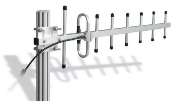
Antenna: Principles, Performance Parameters and Classification

How does an Antenna work?
Catalog |
Ⅰ The function of antennas
The antenna radiates radio waves and receives radio waves. However, the transmitter through the feed line to the antenna is not radio waves. Receiving antenna also can not send radio waves directly through the feed line to the receiver, which must go through the energy conversion process. Here we analyze the signal transmission process as an example of radio communication equipment, and then explain the role of energy conversion of the antenna.

Antenna energy conversion principle diagram
At the transmitter side, the transmitter has been modulated high-frequency oscillation current (energy) by the feeder into the transmitting antenna. Transmitting antenna will be high-frequency current or guide wave (energy) into radio waves - free electromagnetic wave (energy) to the surrounding space radiation (see figure); in the receiving end, radio waves (energy) through the receiving antenna into high-frequency current or guide wave (energy) by the feeder equipment to the receiver. From the above process can be seen, the antenna is not only radiation and receive radio waves device, but also an energy converter is the interface device between the circuit and space.
Ⅱ Principle of Antenna
The principle of the antenna should be divided into two parts, one is the transmitting antenna, another one is the receiving antenna. Transmitting antenna: through an electrode between the antenna and the ground to form a high-frequency electric field into electromagnetic waves, so as to be able to send out and transmit waves to distant places. Receiving antenna: The electromagnetic waves coming from the air are induced into an electric field by an electrode, generating a high-frequency signal voltage, which is sent to the receiver for signal processing.
Ⅲ Antenna performance parameters
1 Working Frequency Range
Frequency range: Whether the antenna or other communication products, always work in a certain frequency range (bandwidth), which depends on the requirements of the indicators. Usually, the target requirements of the frequency range can be the working frequency of the antenna. The width of the working band is called the working bandwidth, the general omnidirectional antenna working bandwidth can reach the center frequency of 3-5%, the directional antenna working bandwidth can reach the center frequency of 5-10%.
2 Input Impedance
Input impedance: antenna input signal voltage and signal current ratio, called the antenna input impedance. The general mobile communication antenna input impedance is 50Ω. Input impedance is related to the structure, size, and work wavelength of the antenna. In the required working frequency range, the input impedance of the imaginary part is very small and the real part is quite close to 50Ω, which means that the antenna and feed line a good impedance matching.
3 Voltage standing wave ratio (VSWR)
VSWR is also known as Voltage Standing Wave Ratio, refers to the ratio of the voltage of the standing wave belly and the amplitude of the voltage of the trough, also known as standing wave coefficient, standing wave ratio. When VSWR is equal to 1, the feed line and the antenna impedance match completely. At this time all high-frequency energy is radiated out by the antenna, there is no energy loss of reflection. When VSWR is infinity, that the total reflection, energy is not radiated out completely.
VSWR is due to the incident wave energy transmission to the antenna input is not all absorbed (radiation) generated by the reflected wave iteration and formed. The larger the VSWR, the greater the reflection, the worse the match. In the mobile communication system, the general requirement of VSWR is less than 1.5.
4 Isolation
Isolation degree on behalf of feed to dual-polarized antenna a port (a polarization) signal in another port (another polarization) in the proportion of the signal.
5 Third Order Intermodulation
Third order intermodulation signal: There are two signals in a linear system. Due to the presence of nonlinear factors, the second harmonic of one signal and the other signal's fundamental waveform to produce a differential beat (mixing) after the parasitic signal. The intermodulation phenomenon is the mixing of two or more carrier frequencies from outside the frequency band after falling in the band of the new frequency components, resulting in the phenomenon of system performance degradation.
6 Power Capacity
Power capacity: the power capacity of the antenna is the maximum continuous RF power that can be continuously added to the antenna without reducing its performance according to the specified conditions in the specified time period.
7 Gain
Antenna gain is used to measure the ability of the antenna to send and receive signals in a particular direction, it is one of the important parameters for choosing the base station antenna. The higher the antenna gain, the better the directionality, the more concentrated the energy, the narrower the flap.
8 H/V-Plane Half Power Beam Width
In the main flap of the power direction map, the relative maximum radiation direction power down to half or less than the maximum 3dB beamwidth angle between the two points is called half-power beamwidth. The horizontal plane of the half-power beamwidth called horizontal plane beamwidth; the vertical plane of the half-power beamwidth is called vertical beamwidth.
9 Electrical Down Tilt
Electric down tilt angle is the maximum radiation pointing on the vertical radiation of the communication antenna and the angle of the antenna is normal. Communication antenna is divided into the fixed down-tilt antenna and electric tilt antenna according to whether it supports electric down tilt adjustment: fixed down-tilt antenna refers to the fixed down-tilt antenna generated by the amplitude and phase assignment of antenna radiation unit array according to the wireless coverage demand. Electric tilt antenna refers to the phase difference of different radiation units in the array through phase shifting unit to produce different radiation main flap down tilt state. Usually, the lower state of the electrical tuning antenna is only within a certain adjustable angle range.
10 Cross Polarization Ratio
The difference between the power level of the antenna with polarization reception (maximum reception level) and the power level of the heteropolar reception (minimum reception level) in the 3dB beamwidth of the directional map.
11 Circularity
Omni-directional antenna directional map circularity is in the horizontal directional map, the maximum or minimum level value and the deviation of the average value. The average value is the arithmetic average of the maximum interval not more than 5 ° orientation level dB value in the horizontal direction map.
12 Polarization
Antenna radiation of the electric field direction of the electromagnetic wave is the antenna polarization direction. If the electric field direction is perpendicular to the ground, we call it vertical polarization; if the electric field direction and the ground parallel, it is called the horizontal polarization; if the electric field direction and the ground is 45 ° angle, it is called +45 ° or -45 ° polarization.
Ⅳ Antenna classification
1 Mechanical antenna
The so-called mechanical antenna is the mobile antenna that uses mechanical adjustment of a downward angle. After the installation of the mechanical antenna, if the requirements of network optimization, it needs to adjust the position of the antenna back bracket to change the tilt angle of the antenna to achieve. In the adjustment process, although the coverage distance of the antenna main flap direction changes obviously, the amplitude of the antenna vertical component and the horizontal component remains unchanged, so the antenna direction map is easy to deform.
Practice proves that: the best mechanical antenna tilt angle is 1~5 degrees; when the tilt angle changes within 5~10 degrees, the antenna direction map changes slightly but not much; when the tilt angle changes between 10~15 degrees, the antenna direction map changes more; when the mechanical antenna tilt more than 15 degrees, the antenna direction map shape changes a lot. Mechanical antenna tilt angle adjustment is very troublesome, generally needs maintenance personnel to climb to the antenna installation to adjust.
2 Electrical tuning antenna

Electrical tuning antenna
The so-called electric tuning antenna is a mobile antenna that uses electronics to adjust the down-tilt angle. The principle of electronic tilt is through changing the phase of the antenna array antenna oscillator, changing the magnitude of the vertical component and horizontal component size, change the synthetic component field strength, so that the vertical direction of the antenna tilt. Because the antenna field strength intensity in each direction increases and decreases at the same time, ensure that the antenna directional map does not change much after changing the inclination angle, so that the main flap direction coverage distance is shortened, and at the same time make the whole directional map in the service cell sector to reduce the coverage area but do not produce interference.
3 Omnidirectional antenna
The Omni-directional antenna has a uniform radiation direction map in the horizontal direction. However, from the vertical direction, the radiation direction map is concentrated, so you can get antenna gain. Arrange the dipole in the same vertical line and feed to each dipole unit correct power and phase can improve the radiation power. The number of dipole units every doubled (also equivalent to double the length), the gain increased by 3 dB. The typical gain is 6 ~ 9 dBd. limited by factors are mainly physical size. For example, 9 dBd gain omnidirectional antenna, its height is 3m.
4 Directional antenna

Directional antenna
This type of antenna horizontal and vertical radiation direction map is non-uniform. It is often used in fan-shaped cells. Therefore, it is also known as sector antenna. The radiation power is more or less concentrated in one direction. The typical value of a directional antenna is 9 ~ 16 dBd.
5 Special antenna
This antenna is used for special purposes, such as indoor, tunnel use.
1.What is called antenna?
An antenna is a metallic structure that captures and/or transmits radio electromagnetic waves. Antennas come in all shapes and sizes from little ones that can be found on your roof to watch TV to really big ones that capture signals from satellites millions of miles away.
2.What is the purpose of the antennas?
Whether it be radio, LAN, or otherwise, an antenna is extremely important. The antennas primary function is to transmit and receive clear signals between multiple wireless points. It is safe to say that an effective and efficient wireless network will require antennas to operate properly.
 Explain in Detail the Three Sharp Weapons to Eliminate EMC: Capacitors/Inductors/Magnetic BeadsUTMEL24 December 20213037
Filter capacitors, common mode inductors, and magnetic beads are all typical components in EMC design circuits, and they're the three main tools for reducing electromagnetic interference.The notion of removing the three principal EMC weapons from the design is examined in-depth in this article.
Read More Everything You Need to Know about RF ChipUTMEL05 January 202216497
RF chip is one of the most important cores of cell phone terminals. The RF chip is responsible for RF transceiver, frequency synthesis, and power amplification.
Read More What are Electromagnetic Waves?UTMEL07 December 20213601
Hello everyone, I am Rose. Today I will introduce Electromagnetic waves to you. Electromagnetic waves are a type of electromagnetic energy.It can be considered the most perfect signal carrier because it can be carried without restriction in open space, as well as through metal transmission lines and controlled freely.
Read More Is Electromagnetic Radiation from Base Stations Terrible?UTMEL06 December 20213051
Hello everyone, I am Rose. Today I will introduce electromagnetic radiation to you. Through this article, I hope that everyone can better understand electromagnetic radiation and protect themselves better.
Read More Antenna: Principles, Performance Parameters and ClassificationUTMEL15 November 20216451
An antenna is a transducer that takes a guided wave propagating on a transmission line and transforms it into an electromagnetic wave propagating in an unbounded medium (usually free space) or vice versa. It is a component used in radio equipment to transmit or receive electromagnetic waves.
Read More
Subscribe to Utmel !
![AR0135AT2M25XUEA0-DPBR]() AR0135AT2M25XUEA0-DPBR
AR0135AT2M25XUEA0-DPBRON Semiconductor
![103MG5]() 103MG5
103MG5Honeywell Sensing and Productivity Solutions
![AR0135CS2M25SUEA0-DRBR1]() AR0135CS2M25SUEA0-DRBR1
AR0135CS2M25SUEA0-DRBR1ON Semiconductor
![FSG15N1A]() FSG15N1A
FSG15N1AHoneywell Sensing and Productivity Solutions
![AS5045B-ASSM]() AS5045B-ASSM
AS5045B-ASSMams
![MT9V034C12STC-DP]() MT9V034C12STC-DP
MT9V034C12STC-DPON Semiconductor
![EM14C0D-E28-L064N]() EM14C0D-E28-L064N
EM14C0D-E28-L064NBourns Inc.
![E69-FCA]() E69-FCA
E69-FCAOmron Automation and Safety
![NOIP1SN012KA-GDI]() NOIP1SN012KA-GDI
NOIP1SN012KA-GDION Semiconductor
![Y92E-B8]() Y92E-B8
Y92E-B8Omron Automation and Safety


