
 Product
 Brand
Brand Articles
 Tools
Tools
Top Tips for Getting Started with EP2C5T144C8N FPGA Boards


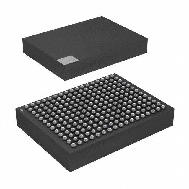
1.6mm mm FPGAs Cyclone® II Series 144-LQFP 0.5mm mm 144
Start your FPGA journey with the EP2C5T144C8N board. Learn its features, setup steps, and beginner tips to create projects like LED blinking and IoT devices.
Product Introduction
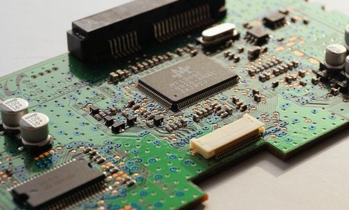
If you've ever wanted to dive into the world of FPGAs, the EP2C5T144C8N is the perfect starting point. Why? It’s affordable, compact, and packed with features that make experimenting easy for first-timers. You don’t need to be an expert in hardware to get started. This board simplifies the process and helps you focus on learning.
Think of this as your beginners guide to FPGAs. You’ll discover how to use the EP2C5T144C8N without feeling overwhelmed. With the right tools and a little guidance, you’ll unlock its potential in no time.
Key Features of the EP2C5T144C8N FPGA Board
The EP2C5T144C8N FPGA board is packed with features that make it a standout choice for beginners and hobbyists. Let’s dive into its key aspects, from technical specifications to its user-friendly design.
Specifications of the EP2C5T144C8N FPGA chip
The EP2C5T144C8N chip is the heart of this FPGA board. It’s designed to handle a variety of tasks, from simple logic circuits to more complex digital systems. Here are some highlights:
Block RAM (BRAM): Ideal for storing data, ranging from a few hundred bits to hundreds of kilobits. This makes it perfect for projects requiring efficient memory usage.
User-defined RAM: Embedded throughout the chip, allowing you to store custom data sets.
Configurable Memory Blocks: You can set up memory blocks of 16 or 36 kb, depending on your project’s needs.
Clock Speed: The chip supports high-speed clocking, ensuring smooth performance for time-sensitive applications.
A study on motor speed measurement systems demonstrated the EP2C5T144C8N’s capabilities. Using Quartus II software and VHDL, the FPGA chip successfully measured small square wave frequencies and displayed results dynamically. This highlights its reliability in real-world applications.
Input/output capabilities and pin layout
The EP2C5T144C8N FPGA board offers a versatile range of input/output (I/O) options, making it easy to connect with external components. Here’s a quick overview of its pin layout and functionality:
| Pin Name | Function Description |
|---|---|
| DQS | Data strobe signal for DDR memory read/write operations. |
| VREF | Reference voltage for DDR memory calibration. |
| SRCC, MRCC | Clock pins that reduce skew and jitter for better performance. |
| PUDC_B | Controls the state of all I/O pins during power-up. |
| AD#P/N | Analog-to-digital converter inputs for digitizing analog signals. |
| PS Pin Names | Used for clock input, reset, and other specific functions. |
The board’s I/O bank architecture supports multiple standards, giving you flexibility in pin assignments. Additionally, it includes special function pins like DQS and SRCC, which are essential for memory control and clock management.
Beginner-friendly features and benefits
If you’re new to FPGA development boards, the EP2C5T144C8N is a fantastic starting point. It’s designed with simplicity and learning in mind. Here’s why it’s so beginner-friendly:
Affordable and Accessible: The board is budget-friendly, making it a great choice for students and hobbyists.
Basic Peripherals: It includes essential components like switches and LEDs, which are perfect for learning the basics of FPGA programming.
Compatibility with Free Tools: You can use free software like Quartus II to program the board, saving you money and reducing the learning curve.
Hands-on Experience: The board’s design encourages experimentation, helping you build confidence as you explore field programmable gate arrays.
Other development boards, like the Basys 3 and Elbert V2, are also popular among beginners. However, the EP2C5T144C8N stands out for its balance of affordability, functionality, and ease of use. It’s a tool that grows with you as you advance in your FPGA journey.
Setting Up the EP2C5T144C8N FPGA Board
Getting your EP2C5T144C8N FPGA board ready for action is an exciting step. With the right tools and a clear plan, you’ll have it up and running in no time. Let’s walk through the essentials, from gathering accessories to powering it up for the first time.
Essential accessories and tools for setup
Before you dive into the setup process, make sure you have everything you need. Here’s a checklist of essential accessories and tools:
USB Blaster Programmer: This is crucial for uploading your Verilog or VHDL code to the FPGA.
Power Supply: A stable 5V power source is recommended for the Cyclone II EP2C5T144 board.
Breadboard and Jumper Wires: These are handy for connecting external components like LEDs or sensors.
Multimeter: Useful for checking connections and ensuring proper voltage levels.
Soldering Kit: If your board requires additional components, a soldering iron and solder wire will come in handy.
Computer with Quartus II Software: You’ll need this to program the FPGA and test your projects.
Tip: If you’re just starting out, consider purchasing a beginner’s FPGA kit that includes the board, programmer, and basic accessories. This saves time and ensures compatibility.
Step-by-step assembly instructions
Setting up your FPGA board might sound intimidating, but it’s simpler than you think. Follow these steps to assemble and prepare your board:
Inspect the Board: Check for any visible damage or missing components. Ensure all solder joints look clean and solid.
Connect the Programmer: Attach the USB Blaster Programmer to the JTAG port on the board. Make sure the connection is secure.
Prepare the Power Supply: Connect the 5V power supply to the board’s power input. Double-check the polarity to avoid damage.
Install Quartus II Software: Download and install the Quartus II software on your computer. This will be your primary tool for FPGA programming.
Load Example Code: Open Quartus II and load a simple Verilog or VHDL project, such as an LED blinking program. This helps verify that the board is functioning correctly.
Upload the Program: Use the USB Blaster to upload the code to the FPGA. Watch for any error messages during the process.
Test the Output: If you’ve uploaded an LED blinking program, check if the LED on the board blinks as expected.
Note: For more advanced projects, you may need to connect additional components like sensors or displays. Use a breadboard for easy prototyping.
Powering the board and performing initial checks
Powering up your FPGA board for the first time is a critical step. Follow these procedures to ensure everything works smoothly:
Check for Shorts: Use a multimeter to verify there are no shorts between the power and ground pins.
Connect the Power Supply: Plug in the 5V power supply and turn it on. Observe the board for any unusual behavior, such as overheating or strange smells.
Verify Voltage Levels: Measure the voltage at key points on the board using a multimeter. Ensure the values match the specifications.
Inspect Component Placement: Look for any misplaced or incorrectly oriented components. Fix any issues before proceeding.
Run a Stability Test: Load a simple program, like an LED blink, and let it run for a few minutes. This tests the board’s stability under load.
Pro Tip: Keep a log of your initial checks, including voltage readings and test results. This can help you troubleshoot issues later.
By following these steps, you’ll set up your EP2C5T144C8N FPGA board with confidence. Once it’s powered up and tested, you’re ready to dive into the exciting world of FPGA programming and hardware development.
Programming Basics for Beginners
Introduction to Quartus II software
To program your EP2C5T144C8N FPGA board, you’ll need Quartus II software. It’s a powerful tool designed specifically for FPGA development. Don’t worry—it’s beginner-friendly once you get the hang of it.
Quartus II lets you create, simulate, and upload your designs to the FPGA. Think of it as the brain behind your board. You’ll use it to write code, test your ideas, and bring your projects to life. The software supports both Verilog and VHDL, so you can choose the language that suits you best.
Here’s how to get started:
Download and Install: Visit Intel’s website and grab the free version of Quartus II. Follow the installation steps.
Create a New Project: Open the software and start a new project. Select the EP2C5T144C8N as your target FPGA.
Write Your Code: Use the built-in editor to write your design.
Simulate and Test: Run simulations to check if your design works as expected.
Upload to FPGA: Use the USB Blaster to transfer your design to the board.
Tip: Quartus II has a steep learning curve, but don’t let that discourage you. Start with simple projects, and you’ll build confidence quickly.
Overview of Verilog and VHDL for FPGA programming
When programming FPGAs, you’ll encounter two main languages: Verilog and VHDL. Both are great for FPGA development, but they have some differences.
| Feature | Verilog | VHDL |
|---|---|---|
| Syntax | Compact, C-like syntax | Verbose, non-C-like syntax |
| Typing | Weakly typed | Strongly typed |
| Code Length | Fewer lines of code | More lines of code |
| Error Checking | Less structured | Better structure and error checking |
| Industry Adoption | Widely adopted | Also widely used, but more niche |
If you’ve worked with Arduino before, Verilog might feel more familiar because of its C-like syntax. On the other hand, VHDL is stricter, which helps catch errors early. For beginners, Verilog is often the easier choice.
Note: Both languages are widely used in the industry, so learning either will serve you well in FPGA development.
Simple project: Blinking an LED with the EP2C5T144C8N
Let’s dive into your first FPGA project: blinking an LED. It’s a classic beginner project that introduces you to FPGA programming.
Here’s what you’ll need:
Your EP2C5T144C8N FPGA board
Quartus II software installed on your computer
A USB Blaster programmer
Follow these steps:
Write the Code: Open Quartus II and create a new Verilog file. Use this simple code:
module blink_led(input CLOCK_50, output reg LED);
    reg [24:0] counter;
    always @(posedge CLOCK_50) begin
        counter <= counter + 1;
        LED <= counter[24];
    end
endmodule
This code toggles the LED on and off using the board’s clock signal.
Compile the Design: Click the compile button in Quartus II to check for errors.
Upload to FPGA: Use the USB Blaster to program the board.
Watch the LED Blink: If everything works, you’ll see the LED blinking at a steady rate.
Pro Tip: Experiment with the counter value to change the blinking speed. This helps you understand how timing works in FPGA design.
This simple project is a great way to get hands-on experience with your FPGA. Once you’ve mastered it, you can move on to more complex designs, like controlling multiple LEDs or integrating sensors.
Overcoming Common Challenges
Understanding digital electronics for FPGA development
Getting comfortable with digital electronics is a big step in mastering FPGA development. You don’t need to be an expert, but understanding the basics will make your journey smoother. Concepts like logic gates, flip-flops, and clock signals are the building blocks of FPGA programming. If these sound unfamiliar, don’t worry—there are plenty of resources to help you.
Here’s a quick look at some educational courses that can strengthen your foundation:
| Course Title | Credits | Key Topics |
|---|---|---|
| Low Power FPGA Hardware for Machine Learning | 3 | Digital systems, hardware architectures, Verilog design, pipelining, and real-world testing. |
| FPGA Synthesis Lab | 3 | VHDL synthesis, system clocking, flip-flop registers, state-machine control, and CAD software. |
These courses focus on practical skills, like designing circuits and testing them in real-world scenarios. Even if you’re learning on your own, you can find similar topics in online tutorials or books.
Debugging code and troubleshooting hardware
Debugging is a skill you’ll develop quickly when working with FPGAs. Mistakes happen, and that’s okay. The key is knowing how to find and fix them. Start by checking your code for syntax errors or typos. Tools like Quartus II can help by pointing out issues during compilation.
When it comes to hardware, having the right tools makes a huge difference. Here are some essentials:
| Tool/Practice | Description |
|---|---|
| In-circuit programmer/debugger | Lets you modify code and set breakpoints for tracing errors. |
| Logic analyzer | Helps you view digital waveforms and communication between devices. |
| Signal generator | Simulates signals to test sensors and other components. |
| Soldering tools and microscope | Useful for repairing or modifying hardware when something isn’t working. |
| Code reuse | Speeds up development by using existing designs and focusing on necessary changes. |
For example, if your LED isn’t blinking, a logic analyzer can check if the clock signal is reaching the pin. If it’s not, you’ll know where to focus your efforts.
Tips for avoiding common beginner mistakes
As a beginner, it’s easy to make mistakes. But with a little preparation, you can avoid many of them. Here are some tips to keep in mind:
Double-check your connections: Misplaced wires or reversed polarity can damage your FPGA board. Always verify before powering up.
Start small: Don’t jump into complex projects right away. Begin with simple tasks, like blinking an LED, to build confidence.
Save your work often: Quartus II can crash unexpectedly. Save your progress frequently to avoid losing hours of work.
Read the datasheet: The EP2C5T144C8N datasheet is your best friend. It contains valuable information about pin layouts and voltage requirements.
Ask for help: Join FPGA forums or communities. Other developers can offer advice and solutions when you’re stuck.
Pro Tip: Keep a notebook to track your progress and document any issues you encounter. This habit will save you time in the long run.
By understanding digital electronics, using the right debugging tools, and avoiding common pitfalls, you’ll overcome challenges with confidence. Every mistake is a learning opportunity, so don’t be afraid to experiment and explore.
Tips for Success with FPGA and IoT Development Boards
Leveraging online resources and tutorials
The internet is your best friend when working with FPGA and IoT development boards. You’ll find countless tutorials, videos, and forums dedicated to helping beginners like you. Start with platforms like YouTube, where creators break down complex topics into bite-sized lessons. Websites like Hackster.io and Instructables also offer step-by-step guides for projects involving IoT and FPGA boards.
Don’t overlook official documentation. Altera provides detailed manuals and datasheets for their FPGA chips. These resources explain pin layouts, power requirements, and programming tips. If you’re stuck, a quick search can often lead you to a solution.
Tip: Bookmark a few trusted websites or channels. Having go-to resources saves time and keeps you focused.
Joining FPGA and IoT communities
Learning alone can feel overwhelming. That’s why joining communities focused on FPGA and IoT development boards is so helpful. Online forums like Reddit’s r/FPGA or Stack Overflow are great places to ask questions and share ideas. You’ll find people who’ve faced the same challenges and are eager to help.
Social media groups and Discord servers are also worth exploring. Many Altera enthusiasts hang out in these spaces, sharing tips and showcasing their projects. You might even find local meetups or hackathons where you can connect with others in person.
Pro Tip: Don’t hesitate to ask questions, no matter how basic they seem. Everyone starts somewhere, and most community members are happy to help.
Experimenting with small IoT projects
The best way to learn is by doing. Start with small IoT projects that use your FPGA board. For example, you could build a temperature monitor using a sensor and display the data on an LCD. Another idea is creating a smart light system that you control with your phone.
These projects teach you how to integrate hardware and software, a key skill for working with IoT development boards. They also help you understand how Altera FPGAs handle real-world tasks.
Note: Keep your projects simple at first. As you gain confidence, you can tackle more complex designs, like home automation systems or IoT-enabled robots.
By leveraging online resources, joining communities, and experimenting with small projects, you’ll quickly build your skills. The world of IoT and FPGA development boards is full of possibilities—dive in and start creating!
The EP2C5T144C8N FPGA board is a fantastic choice for beginners. Its affordability, user-friendly design, and compatibility with free tools like Quartus II make it easy to dive into FPGA development. You’ll find it perfect for experimenting with projects, whether it’s blinking an LED or tackling more advanced designs.
FPGAs are already transforming industries like robotics. They’re powering autonomous robots for tasks like mapping and navigation, thanks to their speed and energy efficiency. Imagine what you can create! Start small, stay curious, and let this board be your gateway to endless possibilities. 🚀
FAQ
What is the EP2C5T144C8N FPGA board used for?
The EP2C5T144C8N FPGA board is perfect for learning digital design and creating custom hardware. You can use it for projects like controlling LEDs, building IoT devices, or experimenting with logic circuits. It’s a great tool for beginners and hobbyists.
Do I need programming experience to use this board?
Not much! If you know basic programming, you’re good to go. Learning Verilog or VHDL might take some time, but tools like Quartus II make it easier. Start with simple projects, and you’ll pick it up quickly.
Can I use the EP2C5T144C8N for IoT projects?
Absolutely! This board works well for IoT experiments. You can connect sensors, process data, and even control devices remotely. Pair it with a microcontroller or Wi-Fi module to unlock more IoT possibilities.
What should I do if my code doesn’t work?
Don’t panic! Check for typos or syntax errors first. Use Quartus II’s error messages to guide you. If it’s a hardware issue, verify your connections with a multimeter. Online forums and FPGA communities are also great for troubleshooting.
Where can I find more resources to learn FPGA programming?
You’ve got plenty of options! Check out YouTube tutorials, FPGA forums, and websites like Hackster.io. The official Altera documentation is also super helpful. Bookmark a few trusted resources to make learning easier.
Tip: Start with beginner-friendly projects like blinking an LED. It’s a fun way to build confidence!
Specifications
- TypeParameter
- Factory Lead Time8 Weeks
- Package / Case
refers to the protective housing that encases an electronic component, providing mechanical support, electrical connections, and thermal management.
144-LQFP - Surface Mount
having leads that are designed to be soldered on the side of a circuit board that the body of the component is mounted on.
YES - Mounting Type
The "Mounting Type" in electronic components refers to the method used to attach or connect a component to a circuit board or other substrate, such as through-hole, surface-mount, or panel mount.
Surface Mount - Number of I/Os89
- Operating Temperature
The operating temperature is the range of ambient temperature within which a power supply, or any other electrical equipment, operate in. This ranges from a minimum operating temperature, to a peak or maximum operating temperature, outside which, the power supply may fail.
0°C~85°C TJ - Packaging
Semiconductor package is a carrier / shell used to contain and cover one or more semiconductor components or integrated circuits. The material of the shell can be metal, plastic, glass or ceramic.
Tray - Series
In electronic components, the "Series" refers to a group of products that share similar characteristics, designs, or functionalities, often produced by the same manufacturer. These components within a series typically have common specifications but may vary in terms of voltage, power, or packaging to meet different application needs. The series name helps identify and differentiate between various product lines within a manufacturer's catalog.
Cyclone® II - Published2008
- JESD-609 Code
The "JESD-609 Code" in electronic components refers to a standardized marking code that indicates the lead-free solder composition and finish of electronic components for compliance with environmental regulations.
e3 - Part Status
Parts can have many statuses as they progress through the configuration, analysis, review, and approval stages.
Active - Moisture Sensitivity Level (MSL)
Moisture Sensitivity Level (MSL) is a standardized rating that indicates the susceptibility of electronic components, particularly semiconductors, to moisture-induced damage during storage and the soldering process, defining the allowable exposure time to ambient conditions before they require special handling or baking to prevent failures
3 (168 Hours) - Number of Terminations144
- ECCN Code
An ECCN (Export Control Classification Number) is an alphanumeric code used by the U.S. Bureau of Industry and Security to identify and categorize electronic components and other dual-use items that may require an export license based on their technical characteristics and potential for military use.
EAR99 - Terminal Finish
Terminal Finish refers to the surface treatment applied to the terminals or leads of electronic components to enhance their performance and longevity. It can improve solderability, corrosion resistance, and overall reliability of the connection in electronic assemblies. Common finishes include nickel, gold, and tin, each possessing distinct properties suitable for various applications. The choice of terminal finish can significantly impact the durability and effectiveness of electronic devices.
Matte Tin (Sn) - Additional Feature
Any Feature, including a modified Existing Feature, that is not an Existing Feature.
ALSO REQUIRES 3.3 SUPPLY - HTS Code
HTS (Harmonized Tariff Schedule) codes are product classification codes between 8-1 digits. The first six digits are an HS code, and the countries of import assign the subsequent digits to provide additional classification. U.S. HTS codes are 1 digits and are administered by the U.S. International Trade Commission.
8542.39.00.01 - Voltage - Supply
Voltage - Supply refers to the range of voltage levels that an electronic component or circuit is designed to operate with. It indicates the minimum and maximum supply voltage that can be applied for the device to function properly. Providing supply voltages outside this range can lead to malfunction, damage, or reduced performance. This parameter is critical for ensuring compatibility between different components in a circuit.
1.15V~1.25V - Terminal Position
In electronic components, the term "Terminal Position" refers to the physical location of the connection points on the component where external electrical connections can be made. These connection points, known as terminals, are typically used to attach wires, leads, or other components to the main body of the electronic component. The terminal position is important for ensuring proper connectivity and functionality of the component within a circuit. It is often specified in technical datasheets or component specifications to help designers and engineers understand how to properly integrate the component into their circuit designs.
QUAD - Terminal Form
Occurring at or forming the end of a series, succession, or the like; closing; concluding.
GULL WING - Peak Reflow Temperature (Cel)
Peak Reflow Temperature (Cel) is a parameter that specifies the maximum temperature at which an electronic component can be exposed during the reflow soldering process. Reflow soldering is a common method used to attach electronic components to a circuit board. The Peak Reflow Temperature is crucial because it ensures that the component is not damaged or degraded during the soldering process. Exceeding the specified Peak Reflow Temperature can lead to issues such as component failure, reduced performance, or even permanent damage to the component. It is important for manufacturers and assemblers to adhere to the recommended Peak Reflow Temperature to ensure the reliability and functionality of the electronic components.
260 - Supply Voltage
Supply voltage refers to the electrical potential difference provided to an electronic component or circuit. It is crucial for the proper operation of devices, as it powers their functions and determines performance characteristics. The supply voltage must be within specified limits to ensure reliability and prevent damage to components. Different electronic devices have specific supply voltage requirements, which can vary widely depending on their design and intended application.
1.2V - Terminal Pitch
The center distance from one pole to the next.
0.5mm - Time@Peak Reflow Temperature-Max (s)
Time@Peak Reflow Temperature-Max (s) refers to the maximum duration that an electronic component can be exposed to the peak reflow temperature during the soldering process, which is crucial for ensuring reliable solder joint formation without damaging the component.
40 - Base Part Number
The "Base Part Number" (BPN) in electronic components serves a similar purpose to the "Base Product Number." It refers to the primary identifier for a component that captures the essential characteristics shared by a group of similar components. The BPN provides a fundamental way to reference a family or series of components without specifying all the variations and specific details.
EP2C5 - JESD-30 Code
JESD-30 Code refers to a standardized descriptive designation system established by JEDEC for semiconductor-device packages. This system provides a systematic method for generating designators that convey essential information about the package's physical characteristics, such as size and shape, which aids in component identification and selection. By using JESD-30 codes, manufacturers and engineers can ensure consistency and clarity in the specification of semiconductor packages across various applications and industries.
S-PQFP-G144 - Number of Outputs81
- Qualification Status
An indicator of formal certification of qualifications.
Not Qualified - Power Supplies
an electronic circuit that converts the voltage of an alternating current (AC) into a direct current (DC) voltage.?
1.21.5/3.33.3V - Number of Inputs89
- Programmable Logic Type
Generally, programmable logic devices can be described as being one of three different types: Simple programmable logic devices (SPLD) Complex programmable logic devices (CPLD) Field programmable logic devices (FPGA).
FIELD PROGRAMMABLE GATE ARRAY - Number of Logic Elements/Cells4608
- Total RAM Bits
Total RAM Bits refers to the total number of memory bits that can be stored in a Random Access Memory (RAM) component. RAM is a type of computer memory that allows data to be accessed in any random order, making it faster than other types of memory like hard drives. The total RAM bits indicate the capacity of the RAM chip to store data temporarily for quick access by the computer's processor. The more total RAM bits a component has, the more data it can store and process at any given time, leading to improved performance and multitasking capabilities.
119808 - Number of LABs/CLBs288
- Number of CLBs288
- Height Seated (Max)
Height Seated (Max) is a parameter in electronic components that refers to the maximum allowable height of the component when it is properly seated or installed on a circuit board or within an enclosure. This specification is crucial for ensuring proper fit and alignment within the overall system design. Exceeding the maximum seated height can lead to mechanical interference, electrical shorts, or other issues that may impact the performance and reliability of the electronic device. Manufacturers provide this information to help designers and engineers select components that will fit within the designated space and function correctly in the intended application.
1.6mm - Width20mm
- Length20mm
- RoHS Status
RoHS means “Restriction of Certain Hazardous Substances” in the “Hazardous Substances Directive” in electrical and electronic equipment.
RoHS Compliant
Datasheet PDF
- Datasheets :
- PCN Packaging :
 A Comprehensive Guide to LTM9012IY-AB#PBF µModule® Simultaneous Sampling ADC
06 March 2024513
 Unveiling the LC88F83B0A 16-bit Microcontroller: In-depth Analysis
29 February 2024120
 LM2575 Step-Down Switching Regulators: Datasheet pdf, Equivalents and Circuit
03 December 20214929
 L7805ACV Voltage Regulator: Pinout, Applications and Datasheet
21 November 20231328
 TIP42C Power Transistor: Pinout, Datasheet, and Applications
22 July 202127600
 IRF644 Power MOSFET: Datasheet, Pinout, Test Circuit
25 September 20212908
 MX25V1635FM1I Flash Memory: Features, Pinout, and Datasheet
18 March 20221398
 APX803S 3-Pin Microprocessor Reset Circuit: Pinout, Equivalent and Datasheet
02 March 20221516
 What is FIR Filter?
24 September 202017396
 SIA's Latest Report: Status and Challenges of US Semiconductors
22 February 20232840
 Detailed Introduction of the Chip Design Process
21 December 202117250
 What is Flexible Sensor?
30 May 20225277
 What is a Delay Circuit? 6 Types of Delay Circuits Explained
28 March 202549028
 AC Contactor: What is Self-Locking?
01 March 202211420
 Linear Induction Motor: Working Principle, Characteristics, and Applications
02 March 202114443
 How to Choose the Best Deep Cycle Battery in 2024 | Reviews and Buying Guide
21 July 20252460
Intel
In Stock: 3600
United States
China
Canada
Japan
Russia
Germany
United Kingdom
Singapore
Italy
Hong Kong(China)
Taiwan(China)
France
Korea
Mexico
Netherlands
Malaysia
Austria
Spain
Switzerland
Poland
Thailand
Vietnam
India
United Arab Emirates
Afghanistan
Åland Islands
Albania
Algeria
American Samoa
Andorra
Angola
Anguilla
Antigua & Barbuda
Argentina
Armenia
Aruba
Australia
Azerbaijan
Bahamas
Bahrain
Bangladesh
Barbados
Belarus
Belgium
Belize
Benin
Bermuda
Bhutan
Bolivia
Bonaire, Sint Eustatius and Saba
Bosnia & Herzegovina
Botswana
Brazil
British Indian Ocean Territory
British Virgin Islands
Brunei
Bulgaria
Burkina Faso
Burundi
Cabo Verde
Cambodia
Cameroon
Cayman Islands
Central African Republic
Chad
Chile
Christmas Island
Cocos (Keeling) Islands
Colombia
Comoros
Congo
Congo (DRC)
Cook Islands
Costa Rica
Côte d’Ivoire
Croatia
Cuba
Curaçao
Cyprus
Czechia
Denmark
Djibouti
Dominica
Dominican Republic
Ecuador
Egypt
El Salvador
Equatorial Guinea
Eritrea
Estonia
Eswatini
Ethiopia
Falkland Islands
Faroe Islands
Fiji
Finland
French Guiana
French Polynesia
Gabon
Gambia
Georgia
Ghana
Gibraltar
Greece
Greenland
Grenada
Guadeloupe
Guam
Guatemala
Guernsey
Guinea
Guinea-Bissau
Guyana
Haiti
Honduras
Hungary
Iceland
Indonesia
Iran
Iraq
Ireland
Isle of Man
Israel
Jamaica
Jersey
Jordan
Kazakhstan
Kenya
Kiribati
Kosovo
Kuwait
Kyrgyzstan
Laos
Latvia
Lebanon
Lesotho
Liberia
Libya
Liechtenstein
Lithuania
Luxembourg
Macao(China)
Madagascar
Malawi
Maldives
Mali
Malta
Marshall Islands
Martinique
Mauritania
Mauritius
Mayotte
Micronesia
Moldova
Monaco
Mongolia
Montenegro
Montserrat
Morocco
Mozambique
Myanmar
Namibia
Nauru
Nepal
New Caledonia
New Zealand
Nicaragua
Niger
Nigeria
Niue
Norfolk Island
North Korea
North Macedonia
Northern Mariana Islands
Norway
Oman
Pakistan
Palau
Palestinian Authority
Panama
Papua New Guinea
Paraguay
Peru
Philippines
Pitcairn Islands
Portugal
Puerto Rico
Qatar
Réunion
Romania
Rwanda
Samoa
San Marino
São Tomé & Príncipe
Saudi Arabia
Senegal
Serbia
Seychelles
Sierra Leone
Sint Maarten
Slovakia
Slovenia
Solomon Islands
Somalia
South Africa
South Sudan
Sri Lanka
St Helena, Ascension, Tristan da Cunha
St. Barthélemy
St. Kitts & Nevis
St. Lucia
St. Martin
St. Pierre & Miquelon
St. Vincent & Grenadines
Sudan
Suriname
Svalbard & Jan Mayen
Sweden
Syria
Tajikistan
Tanzania
Timor-Leste
Togo
Tokelau
Tonga
Trinidad & Tobago
Tunisia
Turkey
Turkmenistan
Turks & Caicos Islands
Tuvalu
U.S. Outlying Islands
U.S. Virgin Islands
Uganda
Ukraine
Uruguay
Uzbekistan
Vanuatu
Vatican City
Venezuela
Wallis & Futuna
Yemen
Zambia
Zimbabwe
![EP1K100FI256-2]() EP1K100FI256-2
EP1K100FI256-2Intel
![EP4CE22F17C8N]() EP4CE22F17C8N
EP4CE22F17C8NIntel
![EP4CE15F23C8N]() EP4CE15F23C8N
EP4CE15F23C8NIntel
![EP3C25E144C8N]() EP3C25E144C8N
EP3C25E144C8NIntel
![EP3C40F484C8N]() EP3C40F484C8N
EP3C40F484C8NIntel
![EP3C10E144I7N]() EP3C10E144I7N
EP3C10E144I7NIntel
![EP4CE6E22I7N]() EP4CE6E22I7N
EP4CE6E22I7NIntel
![EP4CE15F17C8N]() EP4CE15F17C8N
EP4CE15F17C8NIntel
![EP4CE6E22C8N]() EP4CE6E22C8N
EP4CE6E22C8NIntel
![EP3C16F484I7N]() EP3C16F484I7N
EP3C16F484I7NIntel


