nF Capacitors: Definition, Conversion, Circuit Applications, and Selection
Introduction
In the intricate world of electronic components, understanding capacitance units can often be a perplexing challenge for beginners and even seasoned engineers. Among these, the “nF” (nanofarad) frequently stands out, bridging the gap between the minuscule picofarad and the more substantial microfarad. This comprehensive guide aims to be your definitive resource, systematically unraveling everything you need to know about nF capacitors—what they are, how to convert their values, how to read them, and their pivotal role in practical circuits.
We’ll delve into clear explanations, practical insights, and expert-level application knowledge, providing you with the tools to confidently navigate the realm of nanofarad capacitors. Have you ever found yourself scratching your head over a capacitor’s cryptic markings or wondering why a specific nF value is chosen for a particular circuit? You’re not alone. By the end of this article, you’ll possess a robust understanding that empowers you to make informed decisions in your electronic projects.
This article will serve as a detailed roadmap, guiding you through the fundamental concepts, practical identification methods, essential conversion techniques, and diverse applications of nF capacitors. We’ll also touch upon common failure modes and provide strategies for effective selection, ensuring you’re well-equipped to integrate these vital components into your designs.
1.0 What is an nF Capacitor? (What is NF capacitor & NF capacitor meaning)
At its core, an nF capacitor refers to a capacitor whose capacitance is measured in nanofarads (nF). The nanofarad is a unit of electrical capacitance, representing one billionth (10⁻⁹) of a Farad (F). To put this into perspective, the Farad is the base unit of capacitance, but it’s an exceptionally large unit for practical electronic applications. This is why we commonly encounter sub-units like millifarads (mF), microfarads (µF), nanofarads (nF), and picofarads (pF).
1.1 The Capacitance Unit Hierarchy
Imagine capacitance as the ability of a component to store electrical charge, much like a reservoir stores water. The Farad would be an enormous ocean, while a picofarad would be a tiny droplet. The nanofarad, then, occupies a crucial middle ground, offering a “just right” capacity for a vast array of electronic circuits. Here’s a quick look at the hierarchy:
Farad (F): The base unit. 1 F = 1,000 mF = 1,000,000 µF = 1,000,000,000 nF = 1,000,000,000,000 pF
Millifarad (mF): 1 mF = 10⁻³ F
Microfarad (µF): 1 µF = 10⁻⁶ F
Nanofarad (nF): 1 nF = 10⁻⁹ F
Picofarad (pF): 1 pF = 10⁻¹² F
This hierarchical structure allows engineers to work with manageable numbers when designing circuits. For instance, a 1nF capacitor can store 1 billionth of a Coulomb of charge when 1 Volt is applied across it. This seemingly small capacity is precisely what makes nF capacitors indispensable in modern electronics.
1.2 Why nF Capacitors are So Common
nF capacitors are ubiquitous in modern electronics, particularly in applications involving high-frequency signals and precise signal processing. Their “not too big, not too small” capacitance value makes them ideal for tasks where larger capacitors (like µF values) would be too slow to respond to rapid signal changes, and smaller capacitors (like pF values) wouldn’t store enough charge for the intended function. They excel in scenarios requiring moderate charge storage and fast discharge rates.
They are frequently found in: * High-frequency circuits: Where they help in filtering out unwanted noise or coupling signals without significant phase shifts. * Signal processing: Used in filters, oscillators, and timing circuits where precise capacitance values are critical. * Decoupling and bypassing: Providing stable local power to integrated circuits by smoothing out voltage fluctuations and shunting high-frequency noise to ground.
Their versatility and optimal size-to-capacitance ratio contribute to their widespread adoption across consumer electronics, industrial control systems, and communication devices. The ability of a nanofarad capacitor to effectively manage electrical signals at various frequencies makes it a cornerstone component in countless designs.

Figure 1: Visual representation of capacitance unit hierarchy from Farad to picofarad. Image source: BINARYUPDATES
2.0 nF Capacitor Key Parameters: Voltage, Size, and Temperature Drift
When selecting an nF capacitor for your circuit, understanding its key parameters beyond just capacitance is crucial. These parameters directly impact the capacitor’s performance, reliability, and suitability for a given application. Ignoring them can lead to circuit malfunction or premature component failure.
2.1 Voltage Rating (Voltage Rating)
The voltage rating of a capacitor specifies the maximum DC voltage (or peak AC voltage) that can be continuously applied across its terminals without causing damage or breakdown. This is a critical parameter, as exceeding it can lead to dielectric breakdown, short circuits, and even catastrophic failure of the capacitor, potentially damaging other components in the circuit. A common rule of thumb is to select a capacitor with a voltage rating at least 1.5 to 2 times the maximum expected operating voltage in the circuit. For example, if your circuit operates at 12V, a capacitor with a 25V rating would be a safe choice.
2.2 Physical Size (Capacitor Sizes)
The physical size of an nF capacitor varies significantly depending on its type (e.g., ceramic, film) and voltage rating. Smaller capacitors are generally preferred for compact PCB layouts, especially in portable devices. However, there’s often a trade-off: higher capacitance values and higher voltage ratings typically correspond to larger physical dimensions. For instance, a 10nF ceramic capacitor will be much smaller than a 10nF film capacitor, given the same voltage rating. This is a vital consideration during the PCB design phase, where space constraints are often a major challenge. Surface Mount Device (SMD) nF capacitors are particularly popular due to their compact size and suitability for automated assembly processes.
2.3 Temperature Coefficient (Temperature Coefficient)
The temperature coefficient describes how a capacitor’s capacitance changes with variations in ambient temperature. This is especially important in applications where stable performance across a wide temperature range is required. Different dielectric materials used in capacitors exhibit different temperature characteristics. Common temperature coefficients for ceramic capacitors include:
NPO (Negative-Positive-Zero) or C0G: These are Class 1 ceramic capacitors known for their excellent temperature stability, with capacitance change typically less than ±30 ppm/°C (parts per million per degree Celsius) over a wide temperature range (-55°C to +125°C). They are ideal for precision applications like oscillators and timing circuits where capacitance stability is paramount.
X7R: These are Class 2 ceramic capacitors, offering a good balance of capacitance and temperature stability. Their capacitance can vary by up to ±15% over a temperature range of -55°C to +125°C. X7R capacitors are widely used for decoupling, bypassing, and filtering applications where the exact capacitance value is not as critical as its stability over temperature.
Y5V: Also Class 2 ceramic capacitors, Y5V types have the poorest temperature stability among the common types, with capacitance variations up to +22%/-82% over a temperature range of -30°C to +85°C. While they offer high capacitance values in a small package, their significant temperature dependence makes them unsuitable for precision applications. They are typically used in non-critical applications where large capacitance changes can be tolerated, such as power supply filtering.
Understanding these temperature characteristics is crucial for ensuring the long-term reliability and performance of your electronic designs, especially in environments with fluctuating temperatures.

Figure 2: A comparison of different capacitor types, highlighting their typical characteristics and applications.
3.0 How to Read and Identify nF Capacitors? (How to read NF capacitor values)
Identifying the capacitance value of an nF capacitor is a fundamental skill for anyone working with electronics. Unlike resistors, which often use color codes, capacitors typically employ a combination of numerical codes, direct markings, and sometimes color bands (especially older or specialized types). Understanding these markings is essential to ensure you’re using the correct component for your circuit.
3.1 Digital Code Method
The most common method for marking ceramic and some film capacitors is a three-digit numerical code. This code represents the capacitance value in picofarads (pF). The decoding formula is straightforward:
The first two digits represent the significant figures of the capacitance value.
The third digit is a multiplier, indicating the power of 10 by which the first two digits are multiplied. This multiplier specifies the number of zeros to add.
The unit is always picofarads (pF).
Let’s look at some common examples:
102: The first two digits are 10. The third digit is 2, meaning 10². So, 10 x 10² pF = 10 x 100 pF = 1000 pF. Since 1 nF = 1000 pF, a capacitor marked “102” is a 1 nF capacitor.
103: 10 x 10³ pF = 10 x 1000 pF = 10,000 pF = 10 nF.
104: 10 x 10⁴ pF = 10 x 10,000 pF = 100,000 pF = 100 nF.
222: 22 x 10² pF = 22 x 100 pF = 2200 pF = 2.2 nF.
473: 47 x 10³ pF = 47 x 1000 pF = 47,000 pF = 47 nF.
Sometimes, you might encounter an “R” in the code, which indicates a decimal point. For example, “4R7” would mean 4.7 pF.
3.2 Direct Marking Method
Some capacitors, particularly larger film capacitors or those with specific values, may have their capacitance value directly printed on them. This is the easiest to read as it often includes the unit abbreviation.
Examples:
1nF
.001uF (which is equivalent to 1 nF)
47n (meaning 47 nF)
0.1µF (equivalent to 100 nF)
3.3 Color Code Method (Less Common)
While less common for modern nF capacitors, some older or specialized types, particularly certain ceramic disc capacitors, might use a color code similar to resistors. This system typically involves a series of colored bands, each representing a digit, multiplier, and tolerance. If you encounter such a capacitor, it’s best to consult a specific capacitor color code chart, as these can vary. However, for the vast majority of nF capacitors you’ll encounter today, the digital code or direct marking methods are prevalent.
Pro Tip: Always double-check the markings, especially on small components, as misreading a single digit can lead to significant errors in your circuit design.

Figure 3: A visual guide to decoding capacitor values from their markings, including the three-digit code system. Image source: OURPCB
4.0 nF Capacitor Unit Conversion: A Clear Framework (NF capacitor conversion)
Working with capacitors often requires converting values between different units—picofarads (pF), nanofarads (nF), and microfarads (µF). A clear understanding of these conversions is fundamental for accurate circuit design and component selection. While the Farad (F) is the base unit, it’s rarely used directly in practical electronics due to its immense size.
4.1 Core Conversion Relationships
The relationships between pF, nF, and µF are based on powers of 1000:
1 nF = 1,000 pF (Picofarad is 10⁻¹² F, Nanofarad is 10⁻⁹ F, so 10⁻⁹ / 10⁻¹² = 10³)
1 µF = 1,000 nF (Microfarad is 10⁻⁶ F, Nanofarad is 10⁻⁹ F, so 10⁻⁶ / 10⁻⁹ = 10³)
These core relationships allow for straightforward conversions:
To convert pF to nF: Divide by 1,000
To convert nF to pF: Multiply by 1,000
To convert nF to µF: Divide by 1,000
To convert µF to nF: Multiply by 1,000
4.2 nF vs. pF: When Size Matters
The choice between nF and pF capacitors often comes down to the frequency of the signals being handled and the required precision.
Picofarad (pF) capacitors are typically used in very high-frequency applications, such as RF (Radio Frequency) circuits, oscillators, and resonant circuits. Their small capacitance values mean they offer very low impedance at high frequencies, making them ideal for tuning and filtering in the MHz and GHz ranges. They are also preferred when extremely fine adjustments to capacitance are needed.
Nanofarad (nF) capacitors, while still suitable for high-frequency applications, are more commonly found in intermediate frequency filters, coupling, and decoupling circuits. They provide a larger charge storage capacity than pF capacitors, making them effective for filtering out noise in the kHz to low MHz range and for signal coupling where a more substantial charge transfer is required. Their “middle ground” value makes them versatile for a wide range of general-purpose applications.
4.3 nF vs. µF: Power and Storage Needs
When comparing nF and µF capacitors, the primary distinction lies in their capacity for charge storage and their typical applications:
Microfarad (µF) capacitors are significantly larger in capacitance and are generally used in applications requiring substantial charge storage or power supply filtering. They are common in power supply smoothing, energy storage, and low-frequency filtering (e.g., in audio amplifiers or power rectification circuits). Their larger capacitance allows them to store more energy and provide stable voltage rails by effectively smoothing out ripples.
Nanofarad (nF) capacitors, in contrast, are used for more localized and higher-frequency tasks. While µF capacitors handle bulk power delivery and low-frequency noise, nF capacitors are crucial for filtering out high-frequency noise close to integrated circuits (decoupling) and for AC coupling signals between stages without affecting the DC bias. They act as a quick reservoir of charge for sudden current demands or as frequency-selective elements in signal paths.
Important Note: While a 0.1µF capacitor is equivalent to a 100nF capacitor, the notation used often depends on the common practice within a specific application or industry. It’s always good practice to be familiar with both notations.
Capacitor Units Comparison: pF, nF, and µF
Unit Conversion Reference
| Unit | Symbol | Full Name | Relation to Farad | Conversion |
|---|---|---|---|---|
| Picofarad | pF | 10⁻¹² F | 1 pF = 0.000000000001 F | 1 µF = 1,000,000 pF |
| Nanofarad | nF | 10⁻⁹ F | 1 nF = 0.000000001 F | 1 µF = 1,000 nF |
| Microfarad | µF | 10⁻⁶ F | 1 µF = 0.000001 F | 1 nF = 1,000 pF |
Typical Value Ranges and Applications
| Unit | Typical Range | Common Applications | Circuit Function |
|---|---|---|---|
| pF (Picofarad) | 1 pF - 999 pF | • RF circuits<br>• High-frequency filters<br>• Crystal oscillators<br>• Tuning circuits<br>• Parasitic capacitance<br>• Ceramic disc capacitors | • Frequency tuning<br>• RF coupling<br>• High-frequency bypassing<br>• Timing in MHz/GHz circuits |
| nF (Nanofarad) | 1 nF - 999 nF | • Audio circuits<br>• Low-pass filters<br>• Coupling capacitors<br>• Ceramic and film capacitors<br>• Switch debouncing<br>• AC coupling | • Audio frequency filtering<br>• Signal coupling<br>• Timing in kHz circuits<br>• Noise suppression |
| µF (Microfarad) | 1 µF - 10,000+ µF | • Power supply filtering<br>• Energy storage<br>• Motor start capacitors<br>• DC blocking<br>• Electrolytic capacitors<br>• Smoothing circuits | • Power filtering<br>• Energy storage<br>• DC voltage smoothing<br>• Low-frequency bypassing |
Frequency Response Characteristics
| Unit Range | Frequency Domain | Impedance Behavior | Best Use Case |
|---|---|---|---|
| 1-100 pF | Very High (GHz) | Very high impedance at low freq | RF, microwave circuits |
| 100-999 pF | High (100+ MHz) | High impedance at audio freq | VHF/UHF circuits |
| 1-100 nF | Medium (1-100 MHz) | Medium impedance | IF circuits, audio |
| 100-999 nF | Low-Medium (kHz-MHz) | Lower impedance | Audio, general coupling |
| 1-100 µF | Low (Hz-kHz) | Low impedance at high freq | Power supplies, audio |
| 100+ µF | Very Low (DC-Hz) | Very low impedance | Bulk energy storage |
Practical Selection Guide
| Application | Recommended Unit | Typical Values | Why This Unit? |
|---|---|---|---|
| Crystal oscillator | pF | 15-33 pF | Precise frequency control |
| RF bypass | pF | 100-1000 pF | High-frequency noise suppression |
| Audio coupling | nF | 10-470 nF | Good impedance match for audio |
| Timing circuits | nF | 1-100 nF | Convenient RC time constants |
| Power supply filtering | µF | 100-4700 µF | Large charge storage capacity |
| Motor starting | µF | 5-50 µF | High energy storage for starting torque |
Physical Size Relationships
| Unit | Physical Size | Common Package Types |
|---|---|---|
| pF | Very small | 0402, 0603, 0805 SMD |
| nF | Small to medium | 0805, 1206 SMD, small through-hole |
| µF | Medium to large | 1206+ SMD, through-hole, can/axial |
Quick Conversion Examples
| Value | Equivalent Conversions |
|---|---|
| 1 µF | = 1,000 nF = 1,000,000 pF |
| 470 nF | = 0.47 µF = 470,000 pF |
| 2200 pF | = 2.2 nF = 0.0022 µF |
| 10 nF | = 0.01 µF = 10,000 pF |
5.0 nF Capacitor Circuit Applications and Selection Strategies (NF capacitor applications)
nF capacitors are incredibly versatile components, finding their way into nearly every electronic device imaginable. Their specific capacitance range makes them ideal for a variety of functions that are critical for stable and efficient circuit operation. Understanding these applications is key to effective selection.
5.1 General Electronic Applications
From smartphones and computers to industrial machinery and communication systems, nF capacitors play a fundamental role. They are essential in:
Consumer Electronics: Ensuring stable power delivery to microcontrollers, filtering audio signals, and managing timing in various circuits.
Industrial Control: Used in sensor interfaces, motor control, and power conditioning to maintain signal integrity and system reliability.
Telecommunications: Critical for impedance matching, filtering, and coupling in RF and IF stages.
5.2 Specific Circuit Functions
Let’s explore some of the most common and vital roles nF capacitors play in specific circuit configurations:
5.2.1 Filter Circuits (Filter Circuits)
nF capacitors are fundamental building blocks in both high-pass and low-pass filter circuits. They work in conjunction with resistors or inductors to selectively allow or block certain frequencies. For example, in a simple RC (Resistor-Capacitor) low-pass filter, an nF capacitor can shunt high-frequency noise to ground while allowing lower-frequency signals to pass through. Conversely, in a high-pass filter, it can block DC components and low frequencies, allowing only higher frequencies to pass. This makes them invaluable for signal conditioning and noise reduction.
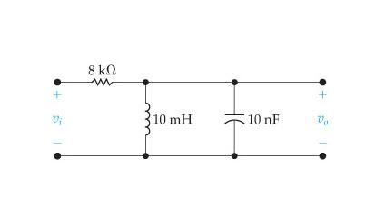
Figure 5: A simplified filter circuit diagram illustrating the placement and function of an nF capacitor.
5.2.2 Decoupling/Bypass Circuits (Decoupling Circuits)
Perhaps one of the most critical applications of nF capacitors is in decoupling or bypass circuits. Integrated circuits (ICs) often draw sudden bursts of current, especially during switching operations, which can cause voltage drops on the power supply lines. These voltage fluctuations can lead to instability and erroneous operation. A small nF capacitor (typically 10nF to 100nF) placed very close to the power pins of an IC acts as a local, high-frequency charge reservoir. It provides the instantaneous current demanded by the IC, preventing the voltage rail from sagging, and simultaneously shunts high-frequency noise generated by the IC back to ground. This ensures a stable and clean power supply for the sensitive digital or analog circuitry.
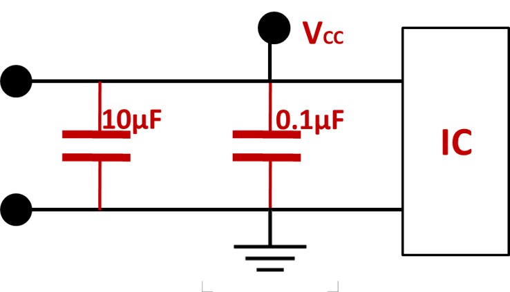
Figure 6: A simplified decoupling circuit diagram, showing an nF capacitor placed near an IC to stabilize power and filter noise.
5.2.3 Audio Applications (Audio Applications)
In audio circuits, nF capacitors are frequently used as coupling capacitors and in tone control networks. As coupling capacitors, they block unwanted DC voltage between amplifier stages while allowing the AC audio signal to pass through. This prevents the DC bias of one stage from interfering with the next. In tone control circuits (like bass and treble controls), nF capacitors, often in conjunction with resistors, form frequency-dependent networks that shape the audio spectrum, allowing users to adjust the sound characteristics.
5.2.4 Parallel and Series Circuits (Parallel/Series Circuits)
Understanding how nF capacitors behave in parallel and series configurations is essential for designing circuits with specific total capacitance values:
Capacitors in Parallel: When nF capacitors are connected in parallel, their individual capacitance values add up. The total capacitance (C_total) is the sum of all individual capacitances: C_total = C1 + C2 + C3 + … This configuration is used to achieve a higher total capacitance than any single capacitor provides.
Capacitors in Series: When nF capacitors are connected in series, the reciprocal of their total capacitance is the sum of the reciprocals of their individual capacitances: 1/C_total = 1/C1 + 1/C2 + 1/C3 + … For two capacitors in series, the formula simplifies to C_total = (C1 * C2) / (C1 + C2). This configuration results in a lower total capacitance than any individual capacitor and is often used to increase the overall voltage rating of the combination.
5.3 Selection Strategies
Choosing the right nF capacitor involves more than just matching the capacitance value. Consider the following decision-making factors:
Application Requirements: What is the primary function? Filtering, decoupling, timing, or coupling? This dictates the required capacitance range and stability.
Frequency Range: Is the circuit operating at high frequencies (RF), audio frequencies, or DC? This influences the capacitor type (ceramic, film) and its ESR (Equivalent Series Resistance) and ESL (Equivalent Series Inductance) characteristics.
Voltage Rating: Ensure the capacitor’s voltage rating is significantly higher than the maximum expected operating voltage.
Temperature Stability: For precision applications, choose NPO/C0G. For general-purpose, X7R is often sufficient. Avoid Y5V for critical functions.
Physical Size and Form Factor: Consider PCB space constraints and whether SMD or through-hole components are required.
Tolerance: How precise does the capacitance value need to be? Common tolerances are ±5%, ±10%, or ±20%.
Cost: Balance performance requirements with budget constraints. More stable or precise capacitors are generally more expensive.
Expert Tip: For decoupling applications, it’s common practice to use multiple capacitors in parallel (e.g., a 100nF ceramic in parallel with a larger µF electrolytic) to effectively filter noise across a broad frequency spectrum. The smaller nF capacitor handles high-frequency noise, while the larger µF capacitor addresses lower-frequency ripple.
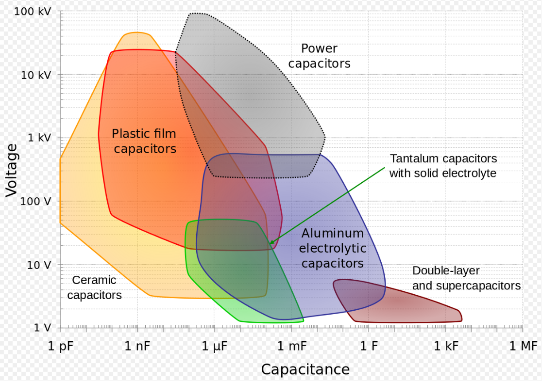
Figure 7: A decision tree guiding the selection of the correct nF capacitor based on application, capacitance range, temperature stability, and cost.
6.0 nF Capacitor Common Failure Modes and Troubleshooting (NF capacitor failure modes)
Even the most robust electronic components can fail, and nF capacitors are no exception. Understanding common failure modes and how to troubleshoot them is essential for diagnosing and repairing electronic circuits. While capacitors are generally reliable, various factors can lead to their degradation or outright failure.
6.1 Common Failure Modes
Capacitor failures typically manifest in a few key ways:
Open Circuit: An open circuit failure occurs when the capacitor loses its ability to store charge, effectively becoming a break in the circuit. This can happen due to internal disconnections, lead breakage, or degradation of the dielectric material. When a capacitor goes open, it no longer performs its intended function (e.g., filtering, coupling), leading to circuit malfunction or complete failure.
Short Circuit: A short circuit failure is often more catastrophic. It happens when the dielectric material breaks down, creating a low-resistance path between the capacitor’s terminals. This can lead to excessive current flow, overheating, and damage to other components in the circuit, potentially causing smoke or even fire. Short circuits are often caused by overvoltage, manufacturing defects, or physical stress.
Capacitance Drop (Degradation): Over time, especially with exposure to heat, voltage stress, or ripple current, a capacitor’s capacitance value can gradually decrease. This degradation might not immediately cause a complete circuit failure but can lead to subtle performance issues, such as reduced filtering effectiveness, altered timing, or signal distortion. This is particularly common in electrolytic capacitors but can also affect ceramic and film types under certain conditions.
6.2 How to Detect Capacitor Failures
Detecting a failed nF capacitor often involves using basic test equipment:
Multimeter (Capacitance Mode): Many modern multimeters have a capacitance measurement function. To test a capacitor, first ensure it is fully discharged (short its leads with a resistor to safely discharge, especially for larger capacitors). Then, remove it from the circuit and connect the multimeter leads across its terminals. The reading should be close to the marked capacitance value. An open capacitor will read zero or out of range, while a shorted one will show very low resistance.
LCR Meter: For more precise measurements, an LCR (Inductance, Capacitance, Resistance) meter is ideal. It can accurately measure capacitance, equivalent series resistance (ESR), and dissipation factor (DF). High ESR or DF values can indicate a degrading capacitor, even if its capacitance value is still within an acceptable range. This is particularly useful for diagnosing subtle performance issues.
6.3 Troubleshooting Checklist
If you suspect a capacitor failure in your circuit, follow this troubleshooting checklist:
Visual Inspection: Look for physical signs of damage, such as bulging (electrolytic), cracks, discoloration, or burnt marks. While nF ceramic and film capacitors are less prone to visible damage, it’s always a good first step.
Circuit Symptoms: Observe the circuit’s behavior. Is there excessive noise, unstable operation, incorrect timing, or unexpected heating? These can be clues pointing to a capacitor issue.
Discharge Capacitor: Always discharge the capacitor before testing or removing it from the circuit to prevent electric shock or damage to your equipment.
In-Circuit vs. Out-of-Circuit Testing: For accurate capacitance measurements, it’s best to remove the capacitor from the circuit. In-circuit testing can be misleading due to parallel components.
Compare with Known Good Component: If possible, compare the readings from the suspected faulty capacitor with a new, known good one of the same value.
Check ESR (if possible): For decoupling and filtering applications, ESR is a critical parameter. If your meter can measure ESR, check if it’s within the expected range for the capacitor type.
Important Note: When replacing a faulty capacitor, always ensure the replacement has the correct capacitance, voltage rating, and temperature characteristics for the application. Using a capacitor with a lower voltage rating or unsuitable temperature coefficient can lead to recurring failures.

Figure 8: A troubleshooting guide for capacitors, outlining common issues and diagnostic steps.
Conclusion
In the vast and intricate landscape of electronics, the nF capacitor stands out as a critical, versatile component, bridging the gap between the microscopic picofarad and the macroscopic microfarad. We’ve explored its fundamental definition as one billionth of a Farad, its physical meaning as a moderate charge storage device, and its indispensable role in a myriad of circuit applications. From meticulously filtering high-frequency noise in sensitive signal processing units to providing crucial decoupling for integrated circuits, the nanofarad capacitor is a testament to precision and efficiency in modern electronic design.
Its significance extends beyond mere capacitance, encompassing vital parameters like voltage rating, physical size, and temperature coefficient, all of which dictate its suitability for diverse environments and applications. Understanding how to accurately read its values, whether through digital codes or direct markings, is a foundational skill for any electronics enthusiast or professional. Furthermore, mastering the art of unit conversion between pF, nF, and µF ensures seamless design and troubleshooting.
As electronics continue to evolve, demanding ever-smaller, more efficient, and more reliable components, the role of the nF capacitor will only grow. Its ability to manage signals across a broad frequency spectrum, coupled with ongoing advancements in material science and manufacturing, ensures its continued relevance in future innovations, from advanced IoT devices to next-generation communication systems. The future of electronics is undoubtedly intertwined with the continued optimization and intelligent application of these small yet mighty components.
We encourage you to share your experiences with nF capacitors in your projects or pose any further questions in the comments section below. Your insights contribute to a richer, more collaborative learning environment for everyone in the electronics community. What challenges have you faced, and what clever solutions have you discovered using nanofarad capacitors?
Video Resources:
For a deeper dive into understanding capacitors and their units, check out these helpful YouTube videos:
Understanding Capacitor Units (pF, nF, µF):
This video provides a comprehensive explanation of capacitor units, including Farad, microfarad, nanofarad, and picofarad, helping to clarify their relationships.
How to Read Capacitor Values:
Learn how to interpret the various codes and markings on capacitors to correctly identify their values.
Common Capacitor Applications:
This video explores 10 common applications of capacitors in electronic circuits, providing practical examples of their use.
Further Reading:
Capacitor Basics: For a foundational understanding of capacitors, their types, and how they work, refer to this comprehensive guide: Electronics Tutorials - Introduction to Capacitors
Decoupling Capacitors Explained: Dive deeper into the critical role of decoupling capacitors in circuit stability: Wikipedia - Decoupling Capacitor
Capacitor Codes and Markings: A detailed resource on how to read various capacitor markings: EffectPedalKits - Reading Capacitor Values
 What is Feedthrough Capacitor?UTMEL06 November 202139259
Hello, everyone. I am Rose. Today I will introduce the feedthrough capacitor to you. The feedthrough capacitor is a three-terminal capacitor that is used to reduce high frequencies. The feedthrough capacitor, unlike regular three-terminal capacitors, is directly installed on the metal panel, resulting in a lower grounding inductance and a negligible effect on the lead inductance.
Read More Detailed Explanation About Twenty Kinds of CapacitorUTMEL08 November 20218256
Hello everyone, I am Rose. Today I will introduce 20 kinds of capacitor to you. I will illustrate them in three or four aspects: Structure, features, Usages, advantages and disadvantages.
Read More What is a Polypropylene Capacitor?UTMEL08 November 202120038
A polypropylene capacitor is a kind of capacitor with a very stable electric capacity. It is often used in applications requiring very precise capacitance and can replace most polyphenylene or mica capacitors.
Read More What is the Difference between MOM, MIM and MOS Capacitors?UTMEL17 April 202564342
This article mainly introduces the structure, principle, advantages and disadvantages of MOM, MIM and MOS capacitors and the difference between them.
Read More What is a Power Capacitor?UTMEL20 November 20215763
Power capacitors are capacitors used in power systems and electrical equipment. Any two pieces of metal conductors are separated by an insulating medium to form a capacitor. The size of the capacitor is determined by its size and the characteristics of the insulating medium between the two plates.
Read More
Subscribe to Utmel !


