How Many Types of Inverters are There?

Inverter and types of inverters
Ⅰ. Classification by input source
Because the inverter's input can be either a voltage or a current source, it's divided into two types: a voltage source inverter (VSI) and a current source inverter (CSI) (CSI).

Figure. 1
Voltage Source Inverter (VSI)
The inverter is known as a voltage source inverter when the input is a continuous DC voltage source.
A rigid DC voltage source with zero impedance is connected to the voltage source inverter's input. In practice, the DC voltage source's impedance is insignificant. The AC output voltage is totally dictated by the state of the switching devices in the inverter and the supplied DC power source, assuming the VSI is powered by an ideal voltage source (a very low impedance source).
Current Source Inverter (CSI)
The inverter is known as a current source inverter when the input is a constant DC current source.
The CSI receives rigid current from a DC power supply with a high impedance. The stiff current is usually provided by a big inductor or a closed-loop control current. The current wave that results is inflexible and unaffected by the load. The switching devices in the inverter, as well as the state of the DC applied power source, decide the AC output current totally.
Ⅱ. Classification by output phase
Inverters are split into two groups based on the output voltage and current phase: single-phase inverters and three-phase inverters.
Single Phase Inverter
A single-phase inverter is a device that converts a single-phase input to a single-phase output. A single-phase inverter's output voltage/current is only one phase with a nominal frequency of 50Hz or a nominal voltage of 60Hz.
The voltage level at which an electrical system runs is known as nominal voltage. 120V, 220V, 440V, 690V, 3.3KV, 6.6KV, 11kV, 33kV, 66kV, 132kV, 220kV, 400kV, and 765kV are some of the nominal voltages. Low nominal voltages can be directly achieved with an inverter utilizing an internal transformer or buck-boost circuit, however high nominal voltages require the use of an external step-up transformer.
For modest loads, single-phase inverters are utilized. The single-phase inverter has a higher single-phase loss and a lower single-phase efficiency than the three-phase inverter. Therefore, three-phase inverters are the first choice for high loads.
Three-phase inverter
Direct current is converted to three-phase power via a three-phase inverter. The three-phase power supply generates three-way alternating current with phase angles that are uniformly spaced. The amplitude and frequency of all three waves produced at the output are the identical, but they differ somewhat due to the load, and each wave is 120 degrees out of phase with the others.
A single three-phase inverter is made up of three single-phase inverters with 120-degree phase separation with each single-phase inverter connects to one of the three load terminals.
Ⅲ. Classification by commutation technology
Line commutation and forced commutation are the two basic types of commutation technology. Auxiliary commutation inverters and complementary commutation inverters are also available, but because they are not widely utilized, we will only cover the two basic varieties here.
Line commutation
The line voltage of the AC circuit is available through these inverters, and the device is turned off when the current in the SCR has a zero characteristic. Line commutation is the name given to this commutation process, and a line commutated inverter is one that works on this basis.
Forced commutation
There is no zero point in the power supply with this sort of commutation. This is why the gadget must be rectified by an external source. Forced commutation is the name given to this commutation technique, and a forced commutation inverter is a device that uses it.

Figure. 2 Comparison and difference between two commutation inverters
Ⅳ. Classification by connection method
The connecting mode of the thyristor in the circuit can be split into three types: series inverter, parallel inverter, and bridge inverter, with half bridge, full bridge, and three-phase bridge being the most common.
Series inverter
A pair of thyristors with an RLC (resistance, inductance, and capacitance) circuit make up a series inverter. One thyristor is linked in series between the DC power source and the RLC circuit, and one thyristor is connected in parallel with the RLC circuit. Because the load is directly connected in series with the DC source using thyristors, these inverters are referred to as series inverters.
Because the load self-commutates the thyristors of a series inverter, it is also known as a self-commutated inverter. This inverter is also known as a "load-commutated inverter." Because the LCR is the load that allows commutation, it is given this name.

Figure. 3
Parallel inverters
Two thyristors, a capacitor, a center-tapped transformer, and an inductor make up a parallel inverter. An inductor is employed to maintain the current source constant while a thyristor provides a conduit for the current to flow. Commutation capacitors attached between these thyristors govern how they turn on and off.
The capacitor is connected in parallel with the load through the transformer, which is why it's called a parallel inverter.
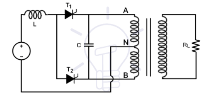
Figure. 4
Half-bridge inverter
To operate, half-bridge inverters require two electronic switches. MOSFETs, IJBTs, BJTs, and thyristors are all examples of switches. Except for strictly resistive loads, half bridges with thyristors and BJT switches require two extra diodes, whereas MOSFETs have built-in body diodes. In summary, two switches are sufficient for strictly resistive loads, but two additional diodes are required for inductive and capacitive loads. Feedback diodes or freewheeling diodes are the names given to these diodes.
A half-bridge inverter's operating concept is the same for all switches, but we're talking about a half-bridge using thyristor switches here. One thyristor is turned on at a time since there are two complimentary thyristors. There are two modes of operation for resistive loads. The output frequency is determined by the switching frequency. When the output frequency is 50HZ, each thyristor is turned on for 20ms at a time.
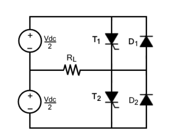
Figure. 5
Full Bridge Inverter
The direction of current flow in the load is controlled by four controlled switches in a single-phase full- bridge inverter , The bridge is equipped with four feedback diodes that return the energy stored in the load to the source. When all thyristors are turned off and the load isn't entirely resistive, these feedback diodes work.
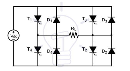
Figure. 6
Only two thyristors are active at any given time for any load. T1 and T2 thyristors will conduct in one cycle, while T3 and T4 thyristors will conduct in the other. To put it another way, when T1 and T2 are turned on, T3 and T4 are turned off, and when T3 and T4 are turned on, the other two are switched off. When more than two thyristors are turned on at the same time, a short circuit occurs, generating excessive heat and burning the circuit.
Three-phase bridge inverter
Three-phase power is required for industrial and other heavy loads. A three-phase inverter is necessary to run these high loads from storage devices or other DC sources. For this, a three-phase bridge inverter can be utilized.
Another form of bridge inverter is a three-phase bridge inverter. which contains six controlled switches and six diodes as indicated.
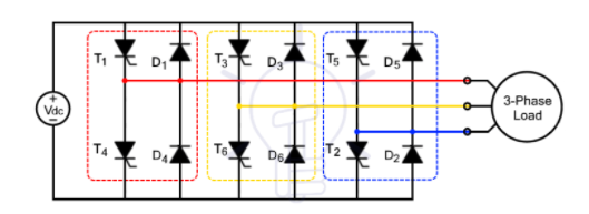
Figure. 7
Ⅴ. Classification by operation modes
Inverters are classified into three types based on their way of operation:
Standalone Inverter
Other power sources will not interrupt the independent inverter because it is directly connected to the load. Stand-alone inverters, often known as "off-grid mode inverters," are inverters that supply electricity to a load without relying on the grid or other power sources.

Figure. 8
Because these inverters are not influenced by the utility grid, they are referred to as off-grid mode inverters, Because they lack the ability to synchronize, these inverters cannot be linked to the utility grid. Synchronization is the process of matching the phase and nominal frequency (50/60hz) of two AC sources.
Grid Inverter
There are two major purposes of a grid-tied inverter (GTI). A grid-tied inverter has two functions: one is to provide AC power from a storage device (DC power source) to an AC load, and the other is to provide additional power to the grid.
Utility-interactive inverters, grid-connected inverters, and grid-feedback inverters all synchronize the frequency and phase of current to suit the utility grid. The voltage level of the inverter is increased to transmit power from the DC source to the utility grid.
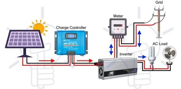
Figure. 9
Bimodal inverter
Bimodal inverters can be used as both grid-connected and stand-alone inverters. When the energy produced by renewables is insufficient, these inverters can inject more energy from renewables and storage devices into the grid, and when the energy produced by renewables is insufficient, they can remove electricity from the grid. In other words, depending on the load requirements, these inverters can operate as stand-alone inverters or grid-tied inverters. Bimodal inverters provide the capabilities of both stand-alone and grid-tied inverters, making them extremely versatile.

Figure. 10
A bimodal inverter's function changes depending on the load. Its role will convert to a stand-alone inverter if there is a grid malfunction or when the renewable energy source's power is sufficient to fulfill the load (it becomes a stand-alone inverter). The transfer switch in this situation disconnects the inverter from the grid.
The operational mode switches from stand-alone to grid-connected once the renewable energy sources start producing additional energy. The inverter begins injecting extra energy into the grid after synchronizing its phase and frequency with the inverter.
Ⅵ. Classification by output waveform
A pure sinusoidal AC output is produced by an ideal inverter, which converts a DC signal. The output signal of practical inverters is not completely sinusoidal, which is a concern. Inverters are classified into three groups based on their output waveform:
Square wave inverter
These are the most basic inverters for converting DC to AC, although the output waveform is not the requisite pure sine wave. The output of these inverters is square waves. To put it another way, these inverters convert DC to AC in the shape of a square wave. Square wave inverters, on the other hand, are less expensive.
An H-bridge inverter is the most basic structure of these inverters. An SPDT (single push double throw) switch before the transformer can be used to make a simpler version, as shown. In addition, the transformer can assist in achieving any desired output voltage level.

Figure. 11
The operation of a given model is extremely straightforward. The current at the output is changed by simply opening and shutting the switch. In other words, a normal inverter's output will produce an AC square wave if the SPDT is switched at the required frequency (ie, a center-tapped transformer). A typical sine wave has roughly 45 percent harmonic distortion, which can be further decreased by using a filter that filters out some harmonics.
Quasi-sine wave Inverter
Inverter with stepped sine wave, also known as a quasi-sine wave inverter. In other words, as positive polarity increases, the output signals of these inverters gradually grow. The output signal begins to progressively decline after reaching the positive peak, until it hits the negative peak, as indicated.

Figure. 12
A quasi-sine wave inverter's structure is far simpler than a pure sine wave inverter's, but slightly more complex than a pure square wave inverter's.
Despite the fact that the inverters' ultimate output waveform is not a pure sine wave, the harmonic distortion of the output is reduced to only 24%. Filtering reduces distortion even more, yet the quantity of distortion remains significant. As a result, these inverters aren't ideal for powering a wide range of loads, including electronic circuits.
Electronics with timers in their circuits can be permanently damaged by quasi-sine waves. All appliances with motors will not perform as efficiently if linked to a quasi-sine wave inverter as they would if connected to a pure sine wave inverter. Also, fast transitions in the waveform can cause noise. Due to these problems, the applications of quasi-sine wave inverters are limited.
Pure Sine Wave Inverter
A pure sinusoidal inverter transforms DC to AC that is almost completely sinusoidal. A pure sine wave inverter's output waveform isn't perfect, but it's far smoother than square wave and quasi-sine wave inverters.
A pure sine wave inverter's output waveform has very few harmonics. Harmonics are sine waves with variable amplitudes that are odd multiples of the fundamental frequency. Harmonics are extremely unwelcome because they can cause major issues with a variety of gadgets. Using various PWM algorithms and then sending the output signal through a low pass filter can further minimize harmonics.

Figure. 13
Because most electrical equipment requires pure sine waves to operate properly, these inverters are preferable to the first two. Square wave or quasi-sine wave inverters, as previously stated, can cause harm to appliances, particularly those with motors. As a result, a pure sine inverter is employed for practical purposes.
Ⅶ. Classification by the number of output levels
Any inverter can have at least two output levels, if not more. Inverters are divided into two types based on the number of output levels: two-level inverters and multi-level inverters.
Two levels inverter
There are two output levels on a two-level inverter. At the base frequency, the output voltage cycles between positive and negative (50Hz or 60Hz).
The output waveform of some so-called "two-level inverters" has three levels. Because one of the levels in a three-level inverter is zero voltage, it falls into this category. Even though zero is the third level, it is still referred to as a two-stage inverter.
A source and switches that control current or voltage make up a two-level inverter circuit. Due to switching losses and device rating limits, two-level inverters are limited in high frequency operation in high voltage applications. However, by combining series and parallel, the switch's rating can be improved. The positive set of switches in a two-level inverter produces the positive half-cycle, while the negative set of switches provides the negative half-cycle.
For the following reasons, two-level inverters are not recommended. To convert power in small voltage steps, inverters must use a limited number of switches and a little quantity of power. Waveforms with less voltage steps will be of higher quality. It also reduces the load's voltage (dv/dt) stress and electromagnetic compatibility concerns. As a result, a multilayer inverter is a better first choice.
Multilevels Inverter (MLI)
The DC signal is converted into a multilayer staircase waveform by the multilevel inverter. The multi-level inverter's output waveform is multi-level alternating rather than directly alternating positive and negative. Because the number of voltage levels is related to the smoothness of the waveform. A multilayer inverter provides a smoother waveform as a result. This characteristic, as previously stated, makes it valuable for practical applications.
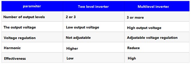
Figure. 14 The difference between two-level inverter and multi-level inverter
Conclusion:
Due to space constraints, this page only covers the 17 most common inverter kinds, but inverters are classified in a variety of ways. Multi-level inverters can be classified as flying capacitor inverters (FCMI), Diode Clamped Inverters (DCMI), and Cascaded H-Bridge Inverters, for example.
Three-phase inverters are preferable for high-load applications, pure sine inverters can safeguard electrical appliances better, and multi-level inverters are more practical options.
1. What are the classifications of photovoltaic inverters?
Central inverter, string inverter, distributed inverter
2. What is a UPS inverter?
It refers to the uninterruptible power supply, there are three categories:
1. Passive backup UPS power supply
2. Online interactive UPS power supply
3. Double conversion UPS power supply
3. What are the types of inverters?
1. According to the nature of the source stream:
Divided into active inverter and Passive inverter
2. According to the type of grid connection:
It is divided into off-grid inverters and grid-connected inverters.
3. According to the topology:
Divided into two-level inverter, three-level inverter, multi-level inverter.
4. According to the power level:
Divided into high-power inverters, medium-power inverters, and low-power inverters.
 Analysis of Wide Bandgap Devices in Renewable Energy SystemsSaumitra Jagdale11 April 20233085
The article will describe the Analysis of Wide Bandgap Devices in Renewable Energy Systems.
Read More Role of Solar Energy in Wide-Band Gap Devices for Photovoltaic ApplicationsSaumitra Jagdale15 March 20242850
The enhancement of photovoltaic systems is closely linked to advancements in power semiconductor devices. Traditional Silicon-based power devices face challenges in meeting market demands for various applications such as EV, PV systems, and other high-power requirements. Presently, power device boasts enhanced efficiency, higher power density, increased blocking voltage, increased switching frequency, reduced cost, and improved reliability.
Read More Modeling, Modulation Analysis of Filter-Integrated Three-Switch Boost InverterRakesh Kumar, Ph.D.12 April 20232871
This article discusses the importance of inverters in energy conversion, the need for filters to eliminate harmonics that can cause system loss and circuit failure, two types of inverters, and an analysis of the three-switch boost inverter topology.
Read More An Analysis of Current-Source Inverters Using High-Frequency WBG SwitchesSaumitra Jagdale09 May 20232960
Hello everyone, welcome to the new post today.
Read More Three Phase Inverter - 180 Degree Conduction ModeRakesh Kumar, Ph.D.05 October 202315376
This technical article illustrates the working of the three phase power electronics inverter in the 180 degree conduction mode. The operation of the six thyristors and the associated waveforms are shown for easier understanding.
Read More
Subscribe to Utmel !
![MC002725]() MC002725
MC002725Multicomp
![MC002734]() MC002734
MC002734Multicomp
![MC002724]() MC002724
MC002724Multicomp
![MC002732]() MC002732
MC002732Multicomp
![MC002735]() MC002735
MC002735Multicomp
![MC002726]() MC002726
MC002726Multicomp
![SSPC25]() SSPC25
SSPC25ABB
![1700006917]() 1700006917
1700006917Advantech
![898197-000]() 898197-000
898197-000TE Connectivity
![MH113-MH1RP-SING-0600]() MH113-MH1RP-SING-0600
MH113-MH1RP-SING-0600Samtec


