
 Product
 Brand
Brand Articles
 Tools
Tools
RGB LED: Circuit, Difference and Application

How an RGB LED works and how to use one! | Basic Electronics
Catalog
| I. Circuit |
| II. Difference |
| III. Application |
The attenuation of RGB and the impact of ultraviolet rays on the human body are both difficult to solve in the short term. Therefore, although both can meet the requirements of white light, they have different results. RGB is obviously more diverse than white LEDs in the application, such as car lights, traffic signs, shop windows, etc. When a certain band of light is needed, the color mixing of RGB can be arbitrary. In contrast, white LEDs are more disadvantaged. So of course the effect is relatively strong. White LEDs are obviously inferior to RGB in terms of clarity and color purity. In addition, the problem of light attenuation and the high cost of wafers make RGB lamps more advantageous.
When the RGB is separated, it can be controlled separately. Although it can be directly controlled and the color mixing is good, it is a big problem to achieve pure white light. Although the cost is expensive, the quality is relatively good. As for the white LED lamp, although The cost is cheap, and it can directly replace CCFL and become the main technology of LED. However, relatively speaking, because of the wavelength and frequency issues, they are packaged together, so the scattering situation will be unstable.
The control problems of RGB lights still need to be strengthened. For example, if one of the lights is broken, it will be quite obvious on the entire screen. On the contrary, the white LED lights can complement each other because they are side-shooting, so they can make up. A broken LED, and the uniformity of the compensation, so that the overall situation does not look too bad.

I. Circuit of RGB LED
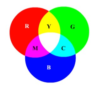
The RGB three-primary color LED color lamp is composed of three independent lamp beads of red, green, and blue. Commonly there are four pins, a common terminal, and three-color control terminals. Any combination of the three colors can produce other colors, such as red and green are bright at the same time, blue is not bright, it is yellow; green and blue are bright at the same time, red is not bright, it is cyan; red and blue are bright at the same time, green is not bright It is magenta; all three colors are bright to produce white. The physical picture and circuit symbols of RGB are shown in the figure below:

The control circuit of RGB light-emitting diodes is extremely simple. In fact, there are three light-emitting diodes with a common positive control circuit as shown in the figure below. To light up a certain light-emitting diode, you only need to give the corresponding pin a low level. The control circuit is shown in the figure below. When the output of the single-chip microcomputer pin is 0, the light-emitting diode is lit, and when the output of the single-chip microcomputer is 1, the light-emitting diode is off.

As mentioned above, to produce the colors yellow, cyan, magenta, and white, the following controls are required:
Yellow: RED=0;GREEN=0;BLUE=1;
Cyan: RED=1;GREEN=0;BLUE=0;
Magenta: RED=0;GREEN=1;BLUE=0;
White: RED=0;GREEN=0;BLUE=0;
The above control methods only realize the two extreme states of light and light. If you want to achieve color gradation or combine more colors, you need to use PWM control.
The principle of PWM control LED is to use the duty cycle to adjust the voltage across the LED, thereby adjusting the current flowing through the LED, the larger the current flowing, the brighter the LED and the smaller the current flowing, the darker the LED. PWM uses this principle to control the color gradation. After the color gradient, more colors can be combined. In the above figure, the three pins that control the LED on and off can be output by the single-chip three-way PWM. You can use the timer to generate PWM, or you can use the PWM on-chip resource of the single-chip to change the duty cycle to adjust the on-off. In the above figure, the larger the duty cycle, the darker the LED.
II. Difference between RGB LED and White LED
Both RGB LED and white LED actually hope to achieve the effect of white light, but one is directly presented with white light (phosphor), and the other is made of mixed light of red, green, and blue.
The imaging principle of RGB lamps: RGB lamps are based on the three primary colors to be integrated together. In addition, there are blue LEDs with yellow phosphors and UV LEDs with RGB phosphors. On the whole, these two have their imaging principles, but the attenuation problem is related to The effects of ultraviolet rays on the human body are difficult to solve in the short term. Therefore, although both can meet the needs of white light, they have different results.

RGB is obviously more diversified than white LEDs in applications. For example, when a certain band of light is needed, such as car lights, traffic signs, shop windows, etc., the color mixing of RGB can be arbitrary. In contrast, white LEDs are It suffers a lot, so of course, the effect is stronger. On the other hand, if RGB LED lights are used in lighting, they will suffer a lot, because the luminous flux, life, and pure color of white light are mainly used in lighting. At present, RGB LED lights are mainly used in decorative lights. aspect.
The clarity and color purity of white LEDs are obviously inferior to RGB. When RGB overlaps properly, the overall brightness and definition are five times that of phosphor white LEDs. In addition, the problem of light attenuation, wafers Expensive.
People who like high picture quality should not be difficult to find that the colors appearing on some LED backlight panels are particularly clear and vivid, even to the extent of high-definition TVs. This situation is the characteristic of RGB, advertised that red is red and green. That is, green and blue are the characteristics of blue. In the light mixing, it has more diversified characteristics.
When the RGB is separated, it can be controlled separately. Although it can be directly controlled and the color mixing is good, it is a big problem to achieve the pure white light. Although the cost is expensive, the quality is relatively good. As for the white LED lamp, although The cost is cheap, and it can directly replace CCFL and become the main technology of LED. However, relatively speaking, because of the wavelength and frequency issues, they are packaged together, so the scattering situation will be unstable.
The control problems of RGB lights still need to be strengthened. For example, if one of the lights is broken, it will be quite obvious on the entire screen. On the contrary, the white LED lights can complement each other because they are side-shooting, so they can make up. A broken LED, and the uniformity of the compensation, so that the overall situation does not look too bad.
III. Application of RGB LED
RGB LED uses three chips, each chip is responsible for generating the color of the light (red, green, and blue). Another way to generate light of different colors is to use red, green, and blue monochromatic LEDs, and then mix and output the light of these LEDs. The application of this kind of LED is suitable for LED drivers of low-power, medium-power, and high-power LEDs, as well as microcontrollers used to control the color of LED modules.

For low-power RGB LEDs, the extremely low-cost BCR40x high-side linear LED driver can be used. The PWM signal generated by the microcontroller can control the color of the LED light. For medium power (0.5W) RGB LEDs or monochromatic LEDs, the new low-side LED drivers BCR321U and BCR421U are the most ideal choices. The BCR321U can be used to adjust the current up to 250mA. Both types of drivers have a direct logic level input, which can be directly controlled by a microcontroller.
All BCR-type LED drivers have a negative thermal coefficient, which means that when the temperature rises, the current will drop at a rate of 0.2%/K. LED drivers such as BCR321U, BCR421U, and BCR40xU are all used in a very small SC-74 package (2.9x2.5x1.1mm) with a power consumption of 1W. The application circuit diagram is shown in Figure 2. The LED driver BCR40xW is even available in a smaller SOT343 package. The scope of application of BCR 320U/420U includes architectural LED lighting; advertising slot type characters; decorative lighting LED strips; commercial lighting for refrigerators and freezers; emergency lighting (step lighting, exit indicators, etc.); interior lighting for ships, trains, and airplanes.
For low-power LEDs (sometimes including medium-power LEDs), the current still commonly used method is a bias resistor. This method has great disadvantages, such as uneven light emission and shortened LED service life. The switch-mode driver, which is an alternative method, cannot meet the price requirement of 0.5W LED products, and the drive circuit is more complicated.
 UTMEL
UTMEL
We are the professional distributor of electronic components, providing a large variety of products to save you a lot of time, effort, and cost with our efficient self-customized service. careful order preparation fast delivery service
Is RGB better than LED?
Although RGB can produce a colour close to white, a dedicated white LED provides a much purer white tone and allows you the option of an extra warm or cool white chip. The extra white chip also provides extra scope for colour mixing with the RGB chips to create a huge range of unique shades.
Can RGB LED make UV?
RGB diodes, the kind you find in an LED computer monitor or television, don't actually produce any wavelength of light you want. Since human eyes aren't sensitive to UV radiation, the trick wouldn't work for ultraviolet wavelengths.
How does an RGB LED work?
An RGB LED is a combination of three LEDs in just one package: red, green and blue; you generate different colors by adjusting the brightness of each of the three LEDs of the RGB LED; to adjust the brightness of each LED, you use a PWM signal.
 Optical Transceiver Guide: How It Works, Types, Form Factors, and SelectionUTMEL24 June 2026180
An optical transceiver is the replaceable interface between electronic network equipment and an optical fiber link. It converts electrical data from a switch, router, server, storage system, or transport platform into modulated light, then converts received light back into electrical data.
Read More Transceivers Shortage Outlook 2026: Supply, Lead Times, and Sourcing OptionsUTMEL09 July 2026286
The 2026 transceiver market is defined not by a broad, systemic silicon crisis, but by a highly targeted, structural constraint driven by AI data center build-outs. Figure 3: Power connectors on server racks designed for intense workloads.
Read More The Introduction to Common Tools and Using Methods of Fiber OpticUTMEL07 January 20227271
The building and maintenance of optical cables in the intelligent industry has gradually expanded with the rapid expansion of the Internet of Things and 5G technologies, resulting in an increase in demand for various optical fiber tools. Cutting shears, for example, come in a variety of shapes and sizes, and each tool serves a different purpose. Do you have any experience with them? When should you utilize certain fiber optic tools?
Read More What are Fiber Optic Patch Cables?UTMEL11 February 20228258
Hello everyone, I am Rose. Today I will introduce fiber optic patch cables to you. Optical fiber communication, as an emerging technology, has become one of the main pillars of modern communication and plays a critical role in modern telecommunication networks, thanks to the rapid growth of traffic data.
Read More Basis of Fiber Optic and Fiber Optic CommunicationUTMEL22 October 20215218
Hello everyone, I am Rose. Today I will introduce fiber optic to you. Fiber Optic is a type of glass or plastic fiber that can be utilized to transmit light. It is mostly used for communication. This article will show you the basic knowledge of fiber optic and fiber optic communication.
Read More
Subscribe to Utmel !
![XPGBWT-01-R250-00FE5]() XPGBWT-01-R250-00FE5
XPGBWT-01-R250-00FE5Cree Inc.
![SLP3-150-100-F]() SLP3-150-100-F
SLP3-150-100-FBivar Inc.
![PLP5-2-250]() PLP5-2-250
PLP5-2-250Bivar Inc.
![MXA8-PW65-0000]() MXA8-PW65-0000
MXA8-PW65-0000Lumileds
![MXA9-PW65-H001]() MXA9-PW65-H001
MXA9-PW65-H001Lumileds
![PLP5-2-625]() PLP5-2-625
PLP5-2-625Bivar Inc.
![5151038F]() 5151038F
5151038FDialight
![LMZ8-SW40]() LMZ8-SW40
LMZ8-SW40Lumileds
![5151070F]() 5151070F
5151070FDialight
![QED522]() QED522
QED522ON Semiconductor


