
 Product
 Brand
Brand Articles
 Tools
Tools
What is Digital Power Supply?

What the Heck is a DIGITAL Power Supply?
Catalog
Ⅵ The difference between the digital power supply and analog power supply |
Ⅰ Introduction
The digital power supply is mainly the external characteristics of the switching power supply. One is the "communication" function of the digital power supply, the second refers to the "NC" function of the digital power supply, and the third refers to the “monitoring” function of the digital power supply, for example, to temperature and other parameters.

the digital power supply circuit board
In recent years, a number of related factors have led to a dramatic increase in the demand for digital power management. Many board designers have turned to the development of intermediate bus power architectures that use multiple single-board DC/DC converters to generate the diverse power requirements required by different silicon devices. The obvious result is that configuring, controlling, and monitoring these power supplies becomes more complex during product design, production testing, and daily use. Specialized programmable ICs and a large number of additional components are required just to control the up/down timing, not to mention the configuration or real-time feedback facilities required for flexible system-level control and diagnostics.
Many of today's high-performance DC/DC converters are still set up and controlled by analog signals generated from simple passive components. Even high-performance converters with the most advanced power conversion topologies may require the use of externally regulated resistors and capacitors to determine things such as action time, output point value, and switching frequency. Of course, none of these parameters can be changed in a hurry, so adaptive power management schemes are not possible.
Most brick converters, intermediate bus converters, and point of load (POL) converters on the market are still analog controlled, except for some converters dedicated to microprocessors that provide limited digital programmability for output voltage control in the form of VID codes. The most pressing need for digital control is for non-isolated point-of-load converters, as these are widely used on the board and provide the final voltage to the device. However, this need also applies to isolated converters, so designers no doubt hope to have other digital programmable power supplies available soon.
Ⅱ Definition of Digital Power Supply
There are several definitions of the digital power supply.
Definition one: Switching power supplies controlled through a digital interface, which emphasizes the "communication" function of the digital power supply.
Definition two: Switching power supply with digital control function. This emphasizes the "NC" function of the digital power supply.
Definition three: Switching power supply with digital monitoring function. It emphasizes the "monitoring" function of the digital power supply for parameters such as temperature.
The common feature of the above three definitions is "modification and upgrading of analog switching power supply", which emphasizes "power control", and the control object is mainly the external characteristics of the switching power supply.
Definition four: It's the power supply product that uses a digital signal processor (DSP) or microcontroller (MCU) as the core, the digital power driver, PWM controller, etc. as the control object, to achieve control, management, and monitoring functions. It is by setting the internal parameters of the switching power supply to change its external characteristics, and the "power control" based on the addition of "power management". Power management refers to the efficient distribution of power to the different components of the system to minimize losses. The management of digital power supplies (e.g., power sequencing) must all be done using digital technology.
Ⅲ Features
1. Intelligent control
It is an intelligent switching power supply system that is composed of a digital signal processor (DSP) or microcontroller (MCU) which serves as the core and the digital power driver and PWM controller as the control object. The traditional switching power supply is controlled by the microcontroller. It generally only controls the start-up and shutdown of the power supply, and it is not the true sense of digital power.
2. Combined optimization of digital and analog components
The use of "Fusion Digital Power" technology enables the optimal combination of analog and digital components in switching power supplies. For example, the power stage used in the analog components of the MOSFET driver, can be easily connected to the digital power controller and achieve a variety of protection and bias power management, while the PWM controller is also a CNC analog chip.
3. High degree of integration
Power System on Chip integrates a large number of discrete components into one chip or a group of chips.
4. High control precision
It can give full play to the advantages of digital signal processors and microcontrollers so that the designed digital power supply can achieve high technical specifications. For example, its pulse-width modulation (PWM) resolution up to 150ps (10~12s) level, which is beyond the reach of traditional switching power supplies. The digital power supply can also achieve multi-phase control, non-linear control, load current sharing and fault prediction, and other functions, providing convenient conditions for the development of green energy-saving switching power supply.
5. High degree of modularity
The high degree of modularity of the digital power supply makes the organic integration between the modules, so that easily form a distributed digital power supply system which improves the reliability of the power system.
Ⅳ Composition structure
The key digital devices of digital power supply are digital power drivers, digital power PWM controllers, and digital signal processors.
(A) driver
The typical applications of digital control power driver chips are Texas Instruments (TI) UCD7100/7201 chips. The difference between the two is UCD7100 for the single-ended output, UCD7201 for the double-ended output, rated output current of ± 4A. They can drive the MOSFET switching power tube and can be adapted to the UCD9110/9501 type digital controller. The main controller can monitor its output current, fast detection of overcurrent fault, and quickly shut down the power supply, the detection period is only 25ns.
Now take the UCD7100 as an example, the chip mainly includes a 3.3V voltage regulator and a reference voltage source, trigger, Schmitt comparator, under-voltage shutdown circuit, control gate, True Drive, and other components. "True Drive" is TI's proprietary technology, which is a hybrid output stage consisting of parallel bipolar transistors and MOSFET tubes that form a pull-up/pull-down circuit. The UCD7100 can provide a peak current to the gate of the MOSFET in a few hundred FIS time, and quickly turn on the driver. The high impedance digital input (IN) of the UCD7100 accepts signals with a logic level of 3.3V and a switching frequency of up to 2MHz. A Schmidt comparator is used to isolate the internal circuitry from external noise. If the PWM output of the controller stops at a high level and an overcurrent fault occurs, the current detection circuit shuts down the output of the driver, and the system can enter retry mode. The UCD7100's internal 3.3V/10mA voltage regulator can be used as a power supply for the digital controller.
(B) Controller
The Texas Instruments (TI) UCD8220/8620 is a dual-ended push-pull PWM controller that is digitally controlled by a DSP or MCU. The difference between the two is that the UCD8220 can utilize a 48V low-voltage start, while the UCD8620 adds 110V high-voltage start circuitry internally.
The chip mainly includes a 3.3V voltage regulator and reference voltage source, pulse-width modulator (PWM), driver logic, push-pull driver, under-voltage shutdown circuit, current-limiting circuit, and a current detection circuit. The UCD8220/8620 can operate in peak current mode or voltage mode and can not only program the limit current but also output a limit current digital flag that can be monitored by the host controller.
(C) Processor
The digital signal processors specifically designed for digital power systems are the UCD9501, TMS320F2808, and TMS320F2806 from Texas Instruments (TI). They mainly contain an internal 100MHz 32-bit CPU, clock oscillator, three 32-bit timers, a watchdog circuit, internal/external interrupt controller, SCI bus, SPI bus, CAN bus and I2C bus interface, 12-way PWM signal output, system controller, 16-channel 12-bit ADC, 16K × 16Flash, 6K × 16SARAM. It adopts a standard 3.3V input/output interface that is fully compatible with the UCD8K series and can be programmed using the Power PADTM HTSSOP and QFN software package.
Ⅴ Basic Principle
The key to the digital power supply is the digital processing of power management and control signals, and its basic requirements are speed, smoothness, and accuracy under the premise of ensuring stability. The following takes a point-of-load converter (POL) as an example to illustrate the principles and methods of implementation of digital power control functions.
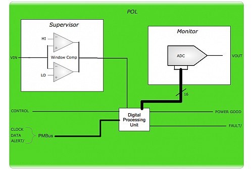
POL structure
A point-of-load converter (POL) is typically used to adjust a DC input voltage (typically 5V to 12V) to a DC output voltage (0.7V to 3.3V) applicable to the load requirements. For example, in a typical circuit based on a Buck switching converter, the Buck converter contains a pulse width modulation (PWM) main control chip, a pair of main power switches, and a low-pass filter consisting of an energy storage inductor and capacitor. A resistive voltage divider samples the output voltage of the power supply and an error amplifier compares this output voltage with a DC reference voltage to produce a voltage error signal, which is an analog signal whose intensity is proportional to the desired output voltage correction. After amplification by an error compensator with some control laws, the output enters a pulse-width modulator (PWM), which generates a pulse wave after comparison with the carrier (usually a sawtooth or triangle) to control the on and off of the power switch (usually a MOSFET). Since MOSFETs have a large input gate capacitance, it is necessary for the driver circuit to efficiently turn them on and off. A separate network of fixed resistor capacitors will typically act as a compensation circuit to ensure a proper balance between dynamic response and stability.
The two other major parts of the power supply are the input and output filter networks. These sections consist of inductors, capacitors, and resistors that can provide several functions. The input filter helps protect the power supply from supply voltage transients, provides some energy storage during dynamic load changes, and comes with a network of filters to allow the power supply to meet the emission specifications caused by its inputs. The output filter stabilizes the output voltage to ensure that the power supply meets its ripple and noise specifications, in addition to storing energy to help maintain the dynamic current requirements of the load circuit. Importantly, the input and output filters and power supply devices will remain essentially the same for analog or digital control architectures.
In a typical digital power control system architecture, the output voltage sensing arrangement is similar to that of an analog system. However, an analog-to-digital converter (ADC) replaces the error amplifier of the analog system, thereby converting the sensed analog voltage values to binary numbers. In addition to the output voltage, it is useful to know other analog parameters such as the output current and temperature of the power supply. While a separate ADC can sense each parameter, it is often more common to take a single ADC and put a multiplexer in front of it. A multiplexer (MUX) will switch between the analog inputs to be measured and send each input to the ADC in turn.
Because the sampling rate of the MUX and ADC is fixed, the ADC outputs a series of numbers for each parameter, each number separated by a known time period. These values are supplied to the microcontroller that provides the processing power for the system. The program memory on the card stores the microcontroller's control algorithms, which are responsible for performing a series of calculations on the ADC's output values. The results of these calculations include parameters such as the error signal, the desired driver-level pulse width, the optimum delay values for the various driver outputs, and loop compensation. With these parameters, the digital pulse width modulator (DPWM) can control the external power MOSFETs after the drive, and the power management section can also communicate with the outside world through certain interfaces and protocols. An external loop compensation element for the analog system is no longer necessary. Reference values for parameters such as output voltage, output current, and temperature limit are stored in non-volatile memory during production or can be entered via the PMBus. At system startup, data are downloaded from the EEPROM into the data memory, and the host chip controls the module's operating status accordingly. At the same time, the default settings in the EEPROM can be read back in with certain external operations.
Ⅵ The difference between the digital power supply and analog power supply
The differences between digital and analog power supplies are mainly focused on the control and communication part. In few applications which are simple and easy-to-use, analog power supply products have an advantage, because its application-specific hardware curing can be achieved. But digital power supply has the advantage in the complex and high-performance system applications which require more controllable factors, faster real-time response, and more multiple analog system power management.
In addition, in complex multi-system business, compared to the analog power supply, the digital power supply is through software programming to achieve a variety of applications. Its scalability and reusability help users easily change the operating parameters to optimize the power system. Through real-time over-current protection and management, it can also reduce the number of peripheral devices.
The digital power supply can be controlled by DSP, as well as MCU. Relatively speaking, the DSP-controlled power supply applies digital filtering, which is better than the MCU-controlled power supply in terms of the complex needs of the power supply. The DSP-controlled power supply has a faster real-time response and better power regulator performance.
 UTMEL
UTMEL
We are the professional distributor of electronic components, providing a large variety of products to save you a lot of time, effort, and cost with our efficient self-customized service. careful order preparation fast delivery service
1.What is a digital power supply?
Digital power supplies are being used increasingly as they are able to provide improved levels of performance over more traditional power supplies. To some, the term digital power supply may loosely refer to a power supply that uses switching technology, i.e. a switch-mode power supply.
2.What are the 3 types of the power supply?
There are three major kinds of power supplies: unregulated (also called brute force), linear regulated, and switching.
3.What is the difference between analog and digital power supply?
There is no real difference between an analog power supply and a digital power supply. Often the two supplies are fed from the same source, but the analogue supply may have a small RC or inductive filter in line to remove digital noise present at the source.
4.What power supply do you need?
The best power supply for your PC build is the one that provides the right amount of wattage to all components simultaneously. Manually calculating this requires that you multiply the total amps of all components by the total volts of all components. The result is the total watts that your PC build requires.
5.What is the power supply and its function?
A power supply is an electrical device that supplies electric power to an electrical load. The primary function of a power supply is to convert electric current from a source to the correct voltage, current, and frequency to power the load.
 LLC Converter with Planar Matrix Transformer for High-Current-High-Power ApplicationsSaumitra Jagdale15 March 20244939
The rise of data centres in recent years, driven by cloud computing and big data, has caused a significant increase in electricity consumption. In the United States alone, it exceeded 70 billion kWh by 2014, making up 1.8% of total national electricity usage.
Read More Norton's Theorem: Working Principle, Circuit Design, and Modern ApplicationsUTMEL27 May 2026560
Norton's theorem simplifies complex linear electrical networks into an equivalent circuit containing a single current source in parallel with a resistor. This article explains the essential five-step workflow for calculating Norton parameters, compares it to its dual, Thévenin's theorem, and explores modern applications in power distribution networks, electric vehicle battery management, and fault diagnosis.
Read More SiC and GaN in 2026:How SiC and GaN Power Devices are Redefining AI Data Centers and 800V EVsUTMEL16 June 20261500
As AI data centers and 800V EVs hit physical thermal limits, the power electronics industry is shifting toward wide-bandgap semiconductors like SiC and GaN. This article explores how these materials are deployed in hybrid topologies to redefine power distribution, detailing high-voltage direct current architectures, engineering challenges in gate driving, and strategic sourcing solutions to build highly efficient, reliable modern power systems.
Read More Enhancing Frequency Stability in Modern Distributed Power SystemsRakesh Kumar, Ph.D.21 September 20244352
The article discusses the importance of primary frequency regulation in maintaining grid stability. It also explores battery energy storage systems, virtual synchronous generators, and advanced control strategies to enhance frequency stability in power systems.
Read More The Impact of SMPS on LED Lighting and Diverse IndustriesUTMEL05 June 20252700
Switched-Mode Power Supplies (SMPS) enhance LED lighting and industries by improving energy efficiency, reliability, and sustainability across diverse applications.
Read More
Subscribe to Utmel !
![LY3F-AC120]() LY3F-AC120
LY3F-AC120Omron Automation and Safety
![JW2SN-DC9V]() JW2SN-DC9V
JW2SN-DC9VPanasonic Electric Works
![RGC1A60D60KGE]() RGC1A60D60KGE
RGC1A60D60KGECarlo Gavazzi Inc.
![JQ1P-24V]() JQ1P-24V
JQ1P-24VPanasonic Electric Works
![LY1-DC24]() LY1-DC24
LY1-DC24Omron Automation and Safety
![JVN1AF-12V-F]() JVN1AF-12V-F
JVN1AF-12V-FPanasonic Electric Works
![3RT20161AF01]() 3RT20161AF01
3RT20161AF01Siemens
![ADW1103W]() ADW1103W
ADW1103WPanasonic Electric Works
![3RH21222BM40]() 3RH21222BM40
3RH21222BM40Siemens
![3RT20241DB443MA0]() 3RT20241DB443MA0
3RT20241DB443MA0Siemens


