What is Network Topology?

Network Topology
Catalog | |
Ⅲ Network Topology Classification
| |
Ⅰ Introduction
The way computers are connected is called "Network Topology". Network topology refers to the physical layout of the various devices interconnected by transmission media, specifically where the computers are located and how the cables pass through them. When designing a network, you should choose the correct topology for your situation. Each topology has its own advantages and disadvantages.
Topology is an abstract representation that does not consider physical properties such as the size and shape of objects, but only uses points or lines to describe the actual locations and relationships of multiple objects. Topology does not care about the details of things or the mutual proportional relationship, but only represents the mutual relationship between multiple objects within a certain range in the form of a graph.
In real life, to interconnect computers and network devices, we must use a certain organizational structure, which is called "topology". The network topology graphically describes the arrangement and configuration of the network and the interrelationship between the nodes. In other words, "topology" means how these computers and communication devices are connected together.
The study of the topological nature of networks and their line graphs is also known as network graph theory. A topology is a contact or connection relationship of a geometry that remains constant when the geometry undergoes continuous plastic deformation. A network structure represented by a line graph consisting of nodes and branches also has this property.
The early study of network topology began in 1736 with a paper on the Königsberg bridge problem by the Swiss mathematician L. Euler. Two papers published by G. R. Kirchhoff in 1845 and 1847 laid the foundation for the application of network topology to the analysis of electrical networks.
Ⅱ Topology Analysis
Figure 1 is an example of an electrical network and its line graph, where the line segments are called branches and the points are called nodes. If each branch has a specified direction it is a directed graph, otherwise, it is an undirected graph. A tree is defined as a connected subgraph that contains all the nodes in the line graph but no loops. The branches in the line graph that belong to the tree are called tree branches, and the others are connected branches. A line graph usually has many trees, and Figure 2 shows some trees of the line graph in Figure 1(b).
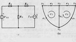
Figure 1. Electric network and its line diagram

Figure 2. Some trees in the line graph Figure 1(b)
Assuming that the line graph has n+1 nodes and b branches, there are exactly n tree branches and b-n branches. The tree can be used to systematically find the largest number of independent loop groups. The method is to select a tree and add a link to the tree to form a loop containing only the link and is called the basic loop. In this way, by With b-n links, a total of b-n independent basic loop groups can be obtained.
Matrix representation of line graph
The relationship between nodes and branches can also be represented by a matrix. This is shown in Figure 3 and Figure 4.

Figure 3. Matrix representation of graph 1

Figure 4. Matrix representation of graph 2
The loop matrix B is a matrix of (b-n) rows and columns b describing the relationship between loops and branches, where a value of 1 for element bij means that branch ej is contained in loop ci and is in the same direction. A value of -1 means the opposite direction, and a value of 0 means that ej is not in loop ci. The B matrix can be formed by a basic loop group or a linear combination thereof, and is a non-singular matrix.
In addition to A and B, there are other matrices describing line graphs, such as cut-set matrices, adjacency matrices, etc., and are collectively referred to as topological matrices.
Electrical network equation
With the help of network topology and matrix methods, the electrical network equations can be systematically established and easily processed by computer. Let Ib and Ub represent the branch current vector and branch voltage vector of the electrical network, respectively, then the Kirchhoff's current law (KCL) and voltage law (KVL) of the circuit can be expressed as
KCL: AIb=0 (n independent equations)
KVL: BUb = O (b - n independent equations)
The resulting b independent equations are determined by the nature of the network topology, together with the b current and voltage relations determined by the nature of the branch components. These are sufficient to solve for the current and voltage of each branch (a total of 2b quantities to be solved). From these three sets of equations, it is also possible to derive a set of equations containing fewer quantities to be found, such as the set of nodal voltage equations, the set of loop current equations, and the set of nodal voltage equations.
Ⅲ Network Topology Classification
1. Star topology
A star topology is a network of workstations connected in a star pattern. The network has a central node. All other nodes (workstations, servers) are directly connected to the central node. This structure is centered on the central node, so it is also called a centralized network.
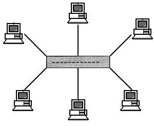
Figure 5. Star network topology
It has the following characteristics:
Simple structure, easy to manage;
Simple control, easy to build the network;
The network delay time is small, transmission error is low.
However, the disadvantages are also obvious: high cost, lower reliability, and poorer resource sharing capability.
2. Ring topology
Ring topology consists of a number of nodes in the network through point-to-point links connected at the beginning and end to form a closed ring. This structure makes the common transmission cable form a ring connection. Data in the ring along a direction between the nodes, information from one node to another node.
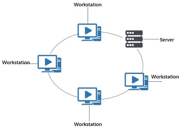
Figure 6. Ring network topology
The ring structure has the following characteristics:
Information flow in the network is along a fixed direction, two nodes have only one path, so the control of path selection is simplified.
Each node on the ring is bootstrap control, so the control software is simple.
Since the information source is serially passed through each node in the loop, when there are too many nodes in the loop, it will affect the information transmission rate and make the response time of the network longer.
The loop is closed, not easy to expand;
low reliability, a node failure will cause the whole network down;
maintenance is difficult, the branch node fault location is difficult.
The advantages of the ring topology: since each node is connected to one node in both directions, the ring topology has natural fault tolerance.
The disadvantages of the ring topology: since there are data streams from both directions, the two directions must be differentiated or restricted to avoid interference with normal communication from indistinguishable redundant data streams. Management and maintenance are more complex.
3. Bus topology
The bus topology means that all workstations and servers are hung on a bus, and all workstations have equal status and are not controlled by a central node. The information on the common bus is mostly transmitted serially in the form of baseband, and its transmission direction always starts from the node sending information and spreads to both ends, just like the information transmitted by a radio station, so it is also called a broadcast computer network. Each node checks the address when receiving information to see if it matches its own workstation address, and receives the information on the network if it does.
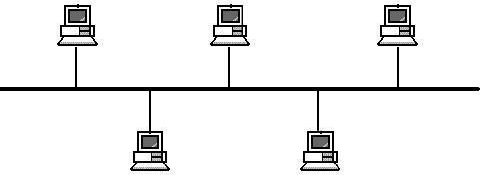
Figure 7. Bus network topology
The bus-based network has the following characteristics:
Simple structure and good expandability. When additional nodes are needed, only a branch interface is needed to connect to the branch nodes, and the bus can be expanded when the bus load does not allow;
Fewer cables are used and easy to install; the equipment used is relatively simple and highly reliable;
Maintenance is difficult, and it is difficult to find fault in branch nodes.
4. Hybrid topology
Hybrid topology is a network structure that combines star or ring structure and bus structure together. Such topology can better meet the expansion of larger networks and solve the limitation of the star network in transmission distance while solving the limitation of the bus network in the number of connected users.
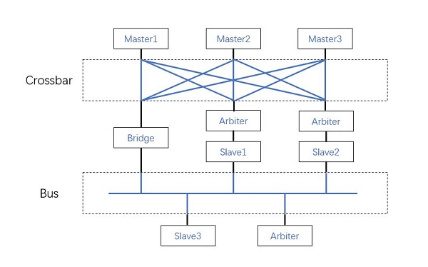
Figure 8. Hybrid topology
Advantages of hybrid topology:
It is widely used, it solves the shortage of star and bus type topology, and meets the actual needs of large companies' network organizations.
The expansion is quite flexible.
Faster speed: Because its backbone uses high-speed coaxial cable or fiber optic cable, the whole network should not be limited much in terms of speed.
Disadvantages of hybrid topology:
Since broadcast-type messaging is still used, it will also be limited in terms of bus length and number of nodes. It also has the weakness that the network rate of bus-type network structure will decrease with the increase of users.
It is difficult to maintain, which is mainly constrained by the bus-type network topology, and if the bus is broken, the whole network will be down.
5. Distributed topology
Distributed topology is a form of network in which computers distributed in different locations are interconnected by lines.
Distributed topology network has the following characteristics:
Due to decentralized control, even if a local failure occurs in the whole network, it will not affect the operation of the whole network, and thus has high reliability;
The path in the network selects the shortest path algorithm, so the network has less delay time and high transmission rate, but Control is complex;
Data links can be established directly between each node, and the information flow is the shortest;
It is easy to share resources within the whole network.
The disadvantages of distributed topology:
Long cables for connecting lines and high cost;
Complicated network management software;
Complex message group exchange, path selection, and flow control;
This structure is not used in general LANs.
6. Tree topology
The tree structure is a hierarchical centralized control network. Compared with star, it has a short total length of communication lines, lower cost, easy expansion of nodes, and easier to find paths. However, except for the leaf node and its connected lines, a failure of any node or its connected lines can cause the system to be affected.
The advantages of tree topology are: easy to expand; easy to isolate faults.

Figure 9. Tree network topology
7. Mesh Topology
In a mesh topology, each device in the network is connected to each other with a point-to-point link. This connection is not economical and is only used when each site has to send information frequently. It is also complex to install, but the system is highly reliable and fault-tolerant. Sometimes it is also called distributed architecture.
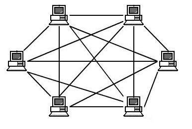
Figure 10. Mesh network topology
8. Cellular topology
Cellular topology is a common structure in wireless LAN. It features point-to-point and multi-point transmission by the wireless transmission medium (microwave, satellite, infrared, etc.) and is a kind of wireless network, which is suitable for city networks, campus networks, and enterprise networks.

Figure 11. Cellular topology
There are other types of topologies in computer networks, such as bus-type mixed with star-type. The network with mixed bus type and ring type connection. In local area networks, the most used are bus-type and star-type structures.
1. What is a network topology?
Network topology describes the physical and logical relationship of nodes in a network, the schematic arrangement of the links and nodes, or some hybrid combination thereof.
2. What are the 8 network topologies?
The study of network topology recognizes eight basic topologies: point-to-point, bus, star, ring or circular, mesh, tree, hybrid, or daisy chain.
 Improving the Energy Conversion Efficiency of Triboelectric NanogeneratorsSaumitra Jagdale19 November 20242425
There is a huge growth in demand for self-sustaining electronic devices, as the traditional power-generating devices fail in remote and harsh environments due to the periodic requirement of battery changes. Also, these devices are frequency specific; some work only in high frequency and some in low frequency. Triboelectric nanogenerators (TENGs) provide a promising solution by efficiently converting mechanical energy into electricity as they are versatile, compact, and cheap, making them a popular choice.
Read More Methodologies for Increasing Efficiency of Fuel Stack Technology for Energy GenerationSaumitra Jagdale19 November 20242534
Presently, power companies are moving towards renewable energy systems. Conventional energy sources are more expensive because they require a vast network to be maintained and huge human resources. Also, they harm the environment by releasing several harmful gases. As the industry’s focus shifts toward renewable energy sources, energy systems powered by Proton Exchange Membrane Fuel Stacks (PEMFS) are gaining traction.
Read More Reconfigurable Antennas: Improving Efficiency in Modern CommunicationRakesh Kumar, Ph.D.24 December 20242354
This article highlights the limitations of conventional antennas and discusses the advantages of reconfigurable antenna designs. It also explores various reconfiguration techniques, applications, and their potential to enhance efficiency.
Read More The Ultimate Guide to AI Noise Reduction Translation EarbudsUTMEL01 April 20254783
In today’s connected world, talking to others is very important. You’ve likely seen how global business, travel, and learning need easy chats in different languages. This need keeps growing because of new tech like 5G and edge computing. These make fast and smooth connections possible.
Read More Comparing Popular Jumper Wires for Electronics ProjectsUTMEL10 July 2025891
Compare top jumper wires for electronics projects in 2025. Explore options by material, length, gauge, and durability to find the best fit for your needs.
Read More
Subscribe to Utmel !
![65812]() 65812
65812TAIYO YUDEN
![6574]() 6574
6574Bourns
![62201-8959]() 62201-8959
62201-8959Molex
![63827-8700]() 63827-8700
63827-8700Molex
![65I/PH2-2P]() 65I/PH2-2P
65I/PH2-2PBahco
![63900-7300]() 63900-7300
63900-7300Molex
![63907-0804]() 63907-0804
63907-0804FLIR
![638084570]() 638084570
638084570Molex
![63456-0802]() 63456-0802
63456-0802Molex
![634640034]() 634640034
634640034Molex


