
 Product
 Brand
Brand Articles
 Tools
Tools
ACS712 Current Sensor: Pinout, Datasheet and Circuit

Hall Effect, Open Loop Sensor 1-Channel Bidirectional -40°C~85°C 5V DC~80kHz Linearity-±1.5%


Hall Effect, Open Loop Sensor 1-Channel Bidirectional -40°C~85°C 5V DC~80kHz Linearity-±1.5%
ACS712 is a fully integrated, hall-effect-based linear current sensor. This blog mainly covers pinout, cad model, circuit and other information about ACS712.

Using the ACS712 Hall Effect Current Sensor Module (part 1)
ACS712 Description
The Allegro™ ACS712 provides economical and precise solutions for AC or DC current sensing in industrial, commercial, and communications systems. The device package allows for easy implementation by the customer. Typical applications include motor control, load detection and management, switchmode power supplies, and overcurrent fault protection. The device is not intended for automotive applications.
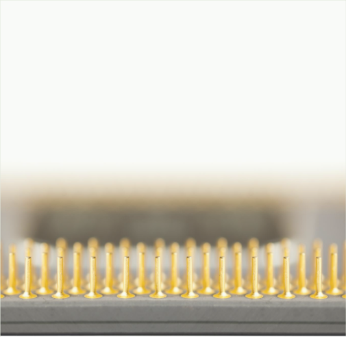
ACS712 Pinout


ACS712 CAD Model
Symbol

Footprint

3D Model

Specifications
- TypeParameter
- Factory Lead Time18 Weeks
- Mounting Type
The "Mounting Type" in electronic components refers to the method used to attach or connect a component to a circuit board or other substrate, such as through-hole, surface-mount, or panel mount.
Surface Mount - Package / Case
refers to the protective housing that encases an electronic component, providing mechanical support, electrical connections, and thermal management.
8-SOIC (0.154, 3.90mm Width) - Surface Mount
having leads that are designed to be soldered on the side of a circuit board that the body of the component is mounted on.
YES - Number of Pins8
- Current Sensing
Current sensing refers to the generation of the voltage signal which is related to the current passing in the circuit.
20A - Operating Temperature
The operating temperature is the range of ambient temperature within which a power supply, or any other electrical equipment, operate in. This ranges from a minimum operating temperature, to a peak or maximum operating temperature, outside which, the power supply may fail.
-40°C~85°C - Packaging
Semiconductor package is a carrier / shell used to contain and cover one or more semiconductor components or integrated circuits. The material of the shell can be metal, plastic, glass or ceramic.
Tape & Reel (TR) - Published2007
- JESD-609 Code
The "JESD-609 Code" in electronic components refers to a standardized marking code that indicates the lead-free solder composition and finish of electronic components for compliance with environmental regulations.
e3 - Pbfree Code
The "Pbfree Code" parameter in electronic components refers to the code or marking used to indicate that the component is lead-free. Lead (Pb) is a toxic substance that has been widely used in electronic components for many years, but due to environmental concerns, there has been a shift towards lead-free alternatives. The Pbfree Code helps manufacturers and users easily identify components that do not contain lead, ensuring compliance with regulations and promoting environmentally friendly practices. It is important to pay attention to the Pbfree Code when selecting electronic components to ensure they meet the necessary requirements for lead-free applications.
yes - Part Status
Parts can have many statuses as they progress through the configuration, analysis, review, and approval stages.
Not For New Designs - Moisture Sensitivity Level (MSL)
Moisture Sensitivity Level (MSL) is a standardized rating that indicates the susceptibility of electronic components, particularly semiconductors, to moisture-induced damage during storage and the soldering process, defining the allowable exposure time to ambient conditions before they require special handling or baking to prevent failures
2 (1 Year) - Number of Terminations8
- Termination
Termination in electronic components refers to the practice of matching the impedance of a circuit to prevent signal reflections and ensure maximum power transfer. It involves the use of resistors or other components at the end of transmission lines or connections. Proper termination is crucial in high-frequency applications to maintain signal integrity and reduce noise.
SMD/SMT - Terminal Finish
Terminal Finish refers to the surface treatment applied to the terminals or leads of electronic components to enhance their performance and longevity. It can improve solderability, corrosion resistance, and overall reliability of the connection in electronic assemblies. Common finishes include nickel, gold, and tin, each possessing distinct properties suitable for various applications. The choice of terminal finish can significantly impact the durability and effectiveness of electronic devices.
Matte Tin (Sn) - Voltage - Supply
Voltage - Supply refers to the range of voltage levels that an electronic component or circuit is designed to operate with. It indicates the minimum and maximum supply voltage that can be applied for the device to function properly. Providing supply voltages outside this range can lead to malfunction, damage, or reduced performance. This parameter is critical for ensuring compatibility between different components in a circuit.
5V - Terminal Position
In electronic components, the term "Terminal Position" refers to the physical location of the connection points on the component where external electrical connections can be made. These connection points, known as terminals, are typically used to attach wires, leads, or other components to the main body of the electronic component. The terminal position is important for ensuring proper connectivity and functionality of the component within a circuit. It is often specified in technical datasheets or component specifications to help designers and engineers understand how to properly integrate the component into their circuit designs.
DUAL - Terminal Form
Occurring at or forming the end of a series, succession, or the like; closing; concluding.
GULL WING - Peak Reflow Temperature (Cel)
Peak Reflow Temperature (Cel) is a parameter that specifies the maximum temperature at which an electronic component can be exposed during the reflow soldering process. Reflow soldering is a common method used to attach electronic components to a circuit board. The Peak Reflow Temperature is crucial because it ensures that the component is not damaged or degraded during the soldering process. Exceeding the specified Peak Reflow Temperature can lead to issues such as component failure, reduced performance, or even permanent damage to the component. It is important for manufacturers and assemblers to adhere to the recommended Peak Reflow Temperature to ensure the reliability and functionality of the electronic components.
260 - Number of Functions1
- Supply Voltage
Supply voltage refers to the electrical potential difference provided to an electronic component or circuit. It is crucial for the proper operation of devices, as it powers their functions and determines performance characteristics. The supply voltage must be within specified limits to ensure reliability and prevent damage to components. Different electronic devices have specific supply voltage requirements, which can vary widely depending on their design and intended application.
5V - Frequency
In electronic components, the parameter "Frequency" refers to the rate at which a signal oscillates or cycles within a given period of time. It is typically measured in Hertz (Hz) and represents how many times a signal completes a full cycle in one second. Frequency is a crucial aspect in electronic components as it determines the behavior and performance of various devices such as oscillators, filters, and communication systems. Understanding the frequency characteristics of components is essential for designing and analyzing electronic circuits to ensure proper functionality and compatibility with other components in a system.
DC~80kHz - Time@Peak Reflow Temperature-Max (s)
Time@Peak Reflow Temperature-Max (s) refers to the maximum duration that an electronic component can be exposed to the peak reflow temperature during the soldering process, which is crucial for ensuring reliable solder joint formation without damaging the component.
40 - Output
In electronic components, the parameter "Output" typically refers to the signal or data that is produced by the component and sent to another part of the circuit or system. The output can be in the form of voltage, current, frequency, or any other measurable quantity depending on the specific component. The output of a component is often crucial in determining its functionality and how it interacts with other components in the circuit. Understanding the output characteristics of electronic components is essential for designing and troubleshooting electronic circuits effectively.
Ratiometric, Voltage - Pin Count
a count of all of the component leads (or pins)
8 - Operating Supply Voltage
The voltage level by which an electrical system is designated and to which certain operating characteristics of the system are related.
5V - Number of Channels1
- Analog IC - Other Type
Analog IC - Other Type is a parameter used to categorize electronic components that are integrated circuits (ICs) designed for analog signal processing but do not fall into more specific subcategories such as amplifiers, comparators, or voltage regulators. These ICs may include specialized analog functions such as analog-to-digital converters (ADCs), digital-to-analog converters (DACs), voltage references, or signal conditioning circuits. They are typically used in various applications where precise analog signal processing is required, such as in audio equipment, instrumentation, communication systems, and industrial control systems. Manufacturers provide detailed specifications for these components to help engineers select the most suitable IC for their specific design requirements.
ANALOG CIRCUIT - Polarization
In electronic components, polarization refers to the orientation or alignment of certain properties within the component. This property can affect the behavior and performance of the component in a circuit. For example, in capacitors, polarization refers to the alignment of the electric field within the dielectric material. Polarized capacitors, such as electrolytic capacitors, have a specific orientation for proper functioning. In other components like diodes, polarization refers to the direction of current flow, which is important for their correct operation. Understanding polarization is crucial for proper usage and integration of electronic components in circuits.
Bidirectional - Output Current
The rated output current is the maximum load current that a power supply can provide at a specified ambient temperature. A power supply can never provide more current that it's rated output current unless there is a fault, such as short circuit at the load.
10mA - Max Supply Current
Max Supply Current refers to the maximum amount of electrical current that a component can draw from its power supply under normal operating conditions. It is a critical parameter that ensures the component operates reliably without exceeding its thermal limits or damaging internal circuitry. Exceeding this current can lead to overheating, performance degradation, or failure of the component. Understanding this parameter is essential for designing circuits that provide adequate power while avoiding overload situations.
13mA - Quiescent Current
The quiescent current is defined as the current level in the amplifier when it is producing an output of zero.
10mA - Response Time
the time taken for a circuit or measuring device, when subjected to a change in input signal, to change its state by a specified fraction of its total response to that change.
5μs - Sensor Type
In electronic components, the parameter "Sensor Type" refers to the specific type of sensor technology used in a particular component to detect and measure physical phenomena such as light, temperature, pressure, motion, or proximity. Different sensor types utilize various principles and mechanisms to convert the detected input into an electrical signal that can be processed by the electronic component. Common sensor types include photodiodes, thermistors, accelerometers, and proximity sensors, each designed for specific applications and environments. Understanding the sensor type is crucial for selecting the right component for a given task and ensuring accurate and reliable sensing capabilities in electronic systems.
Hall Effect, Open Loop - Linearity
In electronic components, linearity refers to the relationship between the input and output signals of the component. A component is said to be linear if its output is directly proportional to its input over a specified range. In other words, when the input signal changes, the output signal changes in a consistent and predictable manner without introducing distortion or non-linear effects.Linearity is an important parameter in electronic components such as amplifiers, filters, and sensors, as it determines the accuracy and fidelity of signal processing. Non-linearities in components can lead to signal distortion, harmonic generation, and other undesirable effects that can degrade the performance of electronic systems.Engineers often characterize the linearity of components by measuring parameters such as gain error, harmonic distortion, and intermodulation distortion. By ensuring that components exhibit good linearity characteristics, designers can create electronic systems that accurately process signals and faithfully reproduce the desired output.
±1.5% - For Measuring
The parameter "For Measuring" in electronic components refers to the specific characteristics or properties of the component that can be measured to determine its performance, functionality, or quality. These parameters are essential for evaluating the behavior of the component in a circuit and ensuring that it meets the required specifications.Common parameters for measuring electronic components include resistance, capacitance, inductance, voltage, current, frequency, temperature coefficient, and power rating. These measurements help engineers and technicians understand how the component will interact with other elements in a circuit and whether it will perform as expected.Accurate measurement of these parameters is crucial for designing and troubleshooting electronic circuits, as deviations from the specified values can lead to malfunctions or failures. Various testing equipment such as multimeters, oscilloscopes, and signal generators are used to measure these parameters accurately.
AC/DC - Sensitivity (mV/A)
The parameter "Sensitivity (mV/A)" in electronic components refers to the ratio of the output voltage to the input current of a sensor or transducer. It indicates how much the output voltage of the component changes in response to a change in the input current. A higher sensitivity value means that a small change in input current will result in a larger change in output voltage, making the component more responsive to variations in the input signal. Sensitivity is an important characteristic in sensors and transducers as it determines the accuracy and precision of the measurements they provide.
100 mV/A - Height1.5mm
- Length4.9mm
- Width3.9mm
- REACH SVHC
The parameter "REACH SVHC" in electronic components refers to the compliance with the Registration, Evaluation, Authorization, and Restriction of Chemicals (REACH) regulation regarding Substances of Very High Concern (SVHC). SVHCs are substances that may have serious effects on human health or the environment, and their use is regulated under REACH to ensure their safe handling and minimize their impact.Manufacturers of electronic components need to declare if their products contain any SVHCs above a certain threshold concentration and provide information on the safe use of these substances. This information allows customers to make informed decisions about the potential risks associated with using the components and take appropriate measures to mitigate any hazards.Ensuring compliance with REACH SVHC requirements is essential for electronics manufacturers to meet regulatory standards, protect human health and the environment, and maintain transparency in their supply chain. It also demonstrates a commitment to sustainability and responsible manufacturing practices in the electronics industry.
No SVHC - Radiation Hardening
Radiation hardening is the process of making electronic components and circuits resistant to damage or malfunction caused by high levels of ionizing radiation, especially for environments in outer space (especially beyond the low Earth orbit), around nuclear reactors and particle accelerators, or during nuclear accidents or nuclear warfare.
No - RoHS Status
RoHS means “Restriction of Certain Hazardous Substances” in the “Hazardous Substances Directive” in electrical and electronic equipment.
ROHS3 Compliant - Lead Free
Lead Free is a term used to describe electronic components that do not contain lead as part of their composition. Lead is a toxic material that can have harmful effects on human health and the environment, so the electronics industry has been moving towards lead-free components to reduce these risks. Lead-free components are typically made using alternative materials such as silver, copper, and tin. Manufacturers must comply with regulations such as the Restriction of Hazardous Substances (RoHS) directive to ensure that their products are lead-free and environmentally friendly.
Lead Free
ACS712 Features and Advantages
Low-noise analog signal path
Device bandwidth is set via the new FILTER pin
5 µs output rise time in response to step input current
80 kHz bandwidth ▪ Total output error 1.5% at TA= 25°C
Small footprint, low-profile SOIC8 package
1.2 mΩ internal conductor resistance
2.1 kVRMS minimum isolation voltage from pins 1-4 to pins 5-8
5.0 V, single supply operation
66 to 185 mV/A output sensitivity
Output voltage proportional to AC or DC currents
Factory-trimmed for accuracy ▪ Extremely stable output offset voltage
Nearly zero magnetic hysteresis
Ratiometric output from supply voltage
ACS712 Functional Block Diagram

ACS712 Alternatives
ACS759, WCS1700, KG190, ACS715
ACS712 Applications
Motor speed control in motor control circuits.
Electrical load detection and management.
Switched-mode power supplies (SMPS)
Protection for over-current.
Where to use ACS712 Module
These ACS712 module can measure current AC or DC current ranging from +5A to -5A, +20A to -20A and +30A to -30A. You have to select the right range for your project since you have to trade off accuracy for higher range modules. This modules outputs Analog voltage (0-5V) based on the current flowing through the wire; hence it is very easy to interface this module with any microcontroller. So if you are looking for a module to measure current using a microcontroller for you project then this module might be the right choice for you.
How to use ACS712
The ACS712 module has two phoenix terminal connectors (green colour ones) with mounting screws as shown above. These are the terminals through which the wire has to be passed. In our case I am measuring the current drawn by the motor so the wires that is going to the load (motor) is passed through the ACS 712 Module. Make sure the module is connected in series with the load and be extra cautious to avoid shorts.
On the other side we have three pins. The Vcc is connected to +5V to power the module and the ground is connected to the ground of the MCU (system). Then the analog voltage given out by the ACS712 module is read using any analog pin on the Microcontroller.
ACS712 Circuit

ACS712 Programming
By default when no current is flowing through the module terminals the output voltage will be +2.5V (Vcc/2), when the current flows in one direction the value will increase from 2.5V and when it flows in other direction the values will decrease from 2.5V. This way the module enables us to measure both AC current and DC current. Let us assume that the microcontroller you are using has a 10-bit ADC and operates at 5V with a reference voltage of 5V for ADC conversion in that case the microcontroller will read the values of ADC from 0 to 1024. Then you can use the formulae below to calculate the Output Voltage from ADC values.
ACS712 Package


ACS712 Manufacturer
Allegro MicroSystems, LLC is a leader in developing, manufacturing and marketing high-performance semiconductors. Allegro's innovative solutions serve high-growth applications within the automotive market, with additional focus on office automation, industrial, and consumer/communications solutions. Allegro is headquartered in Worcester, Massachusetts (USA) with design, applications, and sales support centers located worldwide.
Trend Analysis
Datasheet PDF
- Datasheets :
- PCN Part Status Change :
How do I connect an ACS712 to Arduino?
The ACS712 Current Sensor is a cool little device for making current measurements. Better, its really easy to use with an Arduino. In this sample project, I’ll show you just how easy it is to connect up, program and put to immediate use.An ACS712 Current Sensor Module – I chose to use the 5 amp version. There are 20 amp and 30 amp versions also available. If you’re not all that familiar with this module, you can read my online user manual. If you don’t have one of these modules and think that you may want one, you can try these links. It will only set you back a few dollars.
Where can I find ACS712 Arduino code examples?
The ACS712 is a handy little current sensor from Allegro MicroSystems for low to moderate current sensing applications. SparkFun offers two flavors of breakout board, one with just the sensor and another with an on-board amplifier to increase the sensitivity. The ACS712 sensor uses a Hall effect sensor to output a voltage relative to the current flowing through the IP+ and IP- pins. The advantage of using a Hall effect sensor is that the circuit being sensed and the circuit reading the sensor are electrically isolated. This means that, although your Arduino is running on 5V, the sensed circuit can be operating at higher DC or AC voltages!
How do I measure an ACS712 DC current?
In this tutorial i am going to measure DC current using Acs712 Hall Effect-Based Linear Current Sensor. I am going to measure current precisely. I have gone through various blogs on internet and all of them are measuring current with formulas that are not precise. I will be defining the best method and precise formula generation for measuring the current. I will define each and every step thoroughly and deeply with logic. Project Code is open source and you can download and modify it according to your needs. For this post/tutorial/project i am going to measure only dc current.
How do I use an ACS712 with Raspberry Pi?
The ADC Pi can also be used with the ACS712 range of current sensors to read AC or DC current. The code sample from our GitHub page will allow you to read the 30 amp version of the ACS712 sensor and display the current flow which is updated every second.
How do I connect the the ACS712 to the ESP8266?
Because of the very cheap ACS712 Current Sensor Board modules available all over the place, I really think that everybody heard about ACS712 sensor from Allegro MicroSystems.As I was asked if “Can be used as a current sensor module for our ESP8266 Projects without too much hustle?”, I ordered few of them and let’s explore them for the answer.
 Quadruple Half-H Driver - L293DNE:Datasheet, Pinout, Circuit and Specification
12 April 20226538
![AD584 Precision Voltage Reference: Pinout, Features and Datasheet [FAQ]](https://res.utmel.com/Images/Article/0f6e8ef3-90eb-47b0-bdf7-30e675aaf8f5.png) AD584 Precision Voltage Reference: Pinout, Features and Datasheet [FAQ]
AD584 Precision Voltage Reference: Pinout, Features and Datasheet [FAQ]06 May 20222693
 Essential Tips for Resolving STM32F407ZET6 Connectivity Issues
24 July 2025540
 TL071: Detailed Datasheet, Pinout, and Alternatives Guide
26 January 2026629
 SN754410NEE4 Half-H Driver:Alternatives, Pinout, Schematic
09 September 20211894
 A Comprehensive Guide to LTC6911IMS-2#TRPBF Programmable Gain Instrumentation Amplifier
06 March 2024311
 CD4503 Tri-state Hex Buffer: CD4503 Datasheet PDF, Pinout, CD4503 vs. MC14503
18 January 20222181
 STM32F407ZET6 Microcontroller: Features, Applications and Datasheet
24 November 20237048
 The Rise of Semiconductor Stocks in the Tech Boom
05 December 20233989
 What is inductor: Symbol, Applications and Types
04 January 202210820
 What are Resonators?
07 January 202617683
 UTMEL 2024 Annual gala: Igniting Passion, Renewing Brilliance
18 January 20244877
 What is a Force Sensor?
19 April 202112043
 What is SERDES?
04 November 202124586
 Infrared Thermometer: How it Works? How to Use it?
12 August 20219417
 An Overview of Bipolar Transistors
27 August 20209018
Allegro MicroSystems
In Stock: 3049
United States
China
Canada
Japan
Russia
Germany
United Kingdom
Singapore
Italy
Hong Kong(China)
Taiwan(China)
France
Korea
Mexico
Netherlands
Malaysia
Austria
Spain
Switzerland
Poland
Thailand
Vietnam
India
United Arab Emirates
Afghanistan
Åland Islands
Albania
Algeria
American Samoa
Andorra
Angola
Anguilla
Antigua & Barbuda
Argentina
Armenia
Aruba
Australia
Azerbaijan
Bahamas
Bahrain
Bangladesh
Barbados
Belarus
Belgium
Belize
Benin
Bermuda
Bhutan
Bolivia
Bonaire, Sint Eustatius and Saba
Bosnia & Herzegovina
Botswana
Brazil
British Indian Ocean Territory
British Virgin Islands
Brunei
Bulgaria
Burkina Faso
Burundi
Cabo Verde
Cambodia
Cameroon
Cayman Islands
Central African Republic
Chad
Chile
Christmas Island
Cocos (Keeling) Islands
Colombia
Comoros
Congo
Congo (DRC)
Cook Islands
Costa Rica
Côte d’Ivoire
Croatia
Cuba
Curaçao
Cyprus
Czechia
Denmark
Djibouti
Dominica
Dominican Republic
Ecuador
Egypt
El Salvador
Equatorial Guinea
Eritrea
Estonia
Eswatini
Ethiopia
Falkland Islands
Faroe Islands
Fiji
Finland
French Guiana
French Polynesia
Gabon
Gambia
Georgia
Ghana
Gibraltar
Greece
Greenland
Grenada
Guadeloupe
Guam
Guatemala
Guernsey
Guinea
Guinea-Bissau
Guyana
Haiti
Honduras
Hungary
Iceland
Indonesia
Iran
Iraq
Ireland
Isle of Man
Israel
Jamaica
Jersey
Jordan
Kazakhstan
Kenya
Kiribati
Kosovo
Kuwait
Kyrgyzstan
Laos
Latvia
Lebanon
Lesotho
Liberia
Libya
Liechtenstein
Lithuania
Luxembourg
Macao(China)
Madagascar
Malawi
Maldives
Mali
Malta
Marshall Islands
Martinique
Mauritania
Mauritius
Mayotte
Micronesia
Moldova
Monaco
Mongolia
Montenegro
Montserrat
Morocco
Mozambique
Myanmar
Namibia
Nauru
Nepal
New Caledonia
New Zealand
Nicaragua
Niger
Nigeria
Niue
Norfolk Island
North Korea
North Macedonia
Northern Mariana Islands
Norway
Oman
Pakistan
Palau
Palestinian Authority
Panama
Papua New Guinea
Paraguay
Peru
Philippines
Pitcairn Islands
Portugal
Puerto Rico
Qatar
Réunion
Romania
Rwanda
Samoa
San Marino
São Tomé & Príncipe
Saudi Arabia
Senegal
Serbia
Seychelles
Sierra Leone
Sint Maarten
Slovakia
Slovenia
Solomon Islands
Somalia
South Africa
South Sudan
Sri Lanka
St Helena, Ascension, Tristan da Cunha
St. Barthélemy
St. Kitts & Nevis
St. Lucia
St. Martin
St. Pierre & Miquelon
St. Vincent & Grenadines
Sudan
Suriname
Svalbard & Jan Mayen
Sweden
Syria
Tajikistan
Tanzania
Timor-Leste
Togo
Tokelau
Tonga
Trinidad & Tobago
Tunisia
Turkey
Turkmenistan
Turks & Caicos Islands
Tuvalu
U.S. Outlying Islands
U.S. Virgin Islands
Uganda
Ukraine
Uruguay
Uzbekistan
Vanuatu
Vatican City
Venezuela
Wallis & Futuna
Yemen
Zambia
Zimbabwe
![ACS754SCB-050-PFF]() ACS754SCB-050-PFF
ACS754SCB-050-PFFAllegro MicroSystems
![ACS773ECB-200B-PFF-T]() ACS773ECB-200B-PFF-T
ACS773ECB-200B-PFF-TAllegro MicroSystems
![ACS712ELCTR-05B-T]() ACS712ELCTR-05B-T
ACS712ELCTR-05B-TAllegro MicroSystems
![ACS710KLATR-25CB-T]() ACS710KLATR-25CB-T
ACS710KLATR-25CB-TAllegro MicroSystems
![ACS758LCB-100B-PFF-T]() ACS758LCB-100B-PFF-T
ACS758LCB-100B-PFF-TAllegro MicroSystems
![ACS711KEXLT-15AB-T]() ACS711KEXLT-15AB-T
ACS711KEXLT-15AB-TAllegro MicroSystems
![ACS713ELCTR-20A-T]() ACS713ELCTR-20A-T
ACS713ELCTR-20A-TAllegro MicroSystems
![ACS770LCB-050B-PFF-T]() ACS770LCB-050B-PFF-T
ACS770LCB-050B-PFF-TAllegro MicroSystems
![ACS758ECB-200B-PFF-T]() ACS758ECB-200B-PFF-T
ACS758ECB-200B-PFF-TAllegro MicroSystems
![ACS710KLATR-12CB-T]() ACS710KLATR-12CB-T
ACS710KLATR-12CB-TAllegro MicroSystems


