
An Overview of the 5962-8776303LX Digital to Analog Converter (DAC)


DAC 1.5 B B
This technical article provides an in-depth analysis of the 5962-8776303LX Digital to Analog Converter (DAC) manufactured by Analog Devices, Inc. It explores the features, applications, reference designs, alternative parts, and frequently asked questions about this product. With a focus on its specifications and performance, this article aims to provide a comprehensive understanding of the 5962-8776303LX DAC.
Product Introduction
1. Description:
The 5962-8776303LX is a Digital to Analog Converter (DAC) designed by Analog Devices, Inc. It is a dual-channel DAC with a resolution of 12 bits and a sampling rate of 667 ksps. The DAC utilizes a parallel interface for data communication and operates at a supply voltage range of 10.8V to 16.5V. With a compact CDIP package and through-hole mounting, it is suitable for various electronic applications.
2. Features:
- Dual-channel DAC: The 5962-8776303LX features two independent DAC channels, allowing for simultaneous conversion of digital data to analog signals.
- High resolution and sampling rate: With a 12-bit resolution and a sampling rate of 667 ksps, this DAC provides accurate and fast conversion of digital signals to analog voltages.
- Low settling time: The settling time of 1.5 μs ensures quick stabilization of the analog output voltage after a digital input change.
- Wide operating temperature range: The DAC can operate in extreme temperature conditions, ranging from -55°C to 125°C.
- MIL-STD-883 screening level: The 5962-8776303LX meets the MIL-STD-883 screening requirements, ensuring its reliability and suitability for military applications.
3. Applications:
The 5962-8776303LX DAC finds applications in various industries and electronic systems. Some primary applications include:
- Communication systems: The DAC can be used in communication systems to convert digital signals to analog for modulation and transmission.
- Test and measurement equipment: It can be utilized in test and measurement equipment to generate precise analog signals for calibration and signal generation.
- Industrial automation: The DAC can be integrated into industrial automation systems to provide accurate control signals for motor control, process control, and instrumentation.
- Audio equipment: It can be used in audio equipment, such as digital audio players and audio interfaces, to convert digital audio signals to analog for playback.
Secondary applications of the 5962-8776303LX DAC include aerospace and defense systems, medical equipment, and automotive applications. The DAC can be used in conjunction with specific modules such as microcontrollers, FPGA boards, and DSP processors to enhance system performance and functionality.
4. Reference Designs:
Analog Devices provides several reference designs that utilize the 5962-8776303LX DAC. These reference designs serve as a starting point for system designers and offer valuable insights into the implementation of the DAC in specific applications. Some notable reference designs include:
- High-Speed Data Acquisition System: This reference design demonstrates the use of the DAC in a high-speed data acquisition system, showcasing its performance in capturing and converting analog signals.
- Audio DAC Board: This reference design focuses on the integration of the DAC into an audio system, providing guidelines for achieving high-quality audio output.
5. Alternative Parts:
While the 5962-8776303LX DAC offers excellent performance, there are alternative parts available in the market that cater to different requirements. Some alternatives to consider include the AD5620 DAC from Analog Devices and the MCP4922 DAC from Microchip. These alternatives offer different resolutions, sampling rates, and interface options, allowing designers to choose the most suitable DAC for their specific application.
6. FAQs:
Q1: Is the 5962-8776303LX DAC RoHS compliant?
A1: No, the 5962-8776303LX DAC is not RoHS compliant and contains lead.
Q2: What is the power dissipation of the DAC?
A2: The maximum power dissipation of the 5962-8776303LX DAC is 24mW.
Q3: Can the DAC operate at a voltage below 10.8V?
A3: No, the minimum supply voltage for the DAC is 10.8V.
Q4: What is the settling time of the DAC?
A4: The settling time of the 5962-8776303LX DAC is 1.5 μs.
In conclusion, the 5962-8776303LX DAC by Analog Devices, Inc. offers high performance, reliability, and versatility for various applications. With its dual-channel capability, high resolution, and wide operating temperature range, it is well-suited for communication systems, test and measurement equipment, industrial automation, and audio applications. Designers can explore alternative parts and reference designs to tailor the DAC to their specific requirements.
Specifications
- TypeParameter
- Contact Plating
Contact plating (finish) provides corrosion protection for base metals and optimizes the mechanical and electrical properties of the contact interfaces.
Lead, Tin - Mount
In electronic components, the term "Mount" typically refers to the method or process of physically attaching or fixing a component onto a circuit board or other electronic device. This can involve soldering, adhesive bonding, or other techniques to secure the component in place. The mounting process is crucial for ensuring proper electrical connections and mechanical stability within the electronic system. Different components may have specific mounting requirements based on their size, shape, and function, and manufacturers provide guidelines for proper mounting procedures to ensure optimal performance and reliability of the electronic device.
Through Hole - Package / Case
refers to the protective housing that encases an electronic component, providing mechanical support, electrical connections, and thermal management.
CDIP - Number of Pins24
- Power Dissipation (Max)24mW
- Usage LevelMilitary grade
- JESD-609 Code
The "JESD-609 Code" in electronic components refers to a standardized marking code that indicates the lead-free solder composition and finish of electronic components for compliance with environmental regulations.
e0 - Pbfree Code
The "Pbfree Code" parameter in electronic components refers to the code or marking used to indicate that the component is lead-free. Lead (Pb) is a toxic substance that has been widely used in electronic components for many years, but due to environmental concerns, there has been a shift towards lead-free alternatives. The Pbfree Code helps manufacturers and users easily identify components that do not contain lead, ensuring compliance with regulations and promoting environmentally friendly practices. It is important to pay attention to the Pbfree Code when selecting electronic components to ensure they meet the necessary requirements for lead-free applications.
no - Number of Terminations24
- Terminal Finish
Terminal Finish refers to the surface treatment applied to the terminals or leads of electronic components to enhance their performance and longevity. It can improve solderability, corrosion resistance, and overall reliability of the connection in electronic assemblies. Common finishes include nickel, gold, and tin, each possessing distinct properties suitable for various applications. The choice of terminal finish can significantly impact the durability and effectiveness of electronic devices.
Tin/Lead (Sn/Pb) - Max Operating Temperature
The Maximum Operating Temperature is the maximum body temperature at which the thermistor is designed to operate for extended periods of time with acceptable stability of its electrical characteristics.
125°C - Min Operating Temperature
The "Min Operating Temperature" parameter in electronic components refers to the lowest temperature at which the component is designed to operate effectively and reliably. This parameter is crucial for ensuring the proper functioning and longevity of the component, as operating below this temperature may lead to performance issues or even damage. Manufacturers specify the minimum operating temperature to provide guidance to users on the environmental conditions in which the component can safely operate. It is important to adhere to this parameter to prevent malfunctions and ensure the overall reliability of the electronic system.
-55°C - Terminal Position
In electronic components, the term "Terminal Position" refers to the physical location of the connection points on the component where external electrical connections can be made. These connection points, known as terminals, are typically used to attach wires, leads, or other components to the main body of the electronic component. The terminal position is important for ensuring proper connectivity and functionality of the component within a circuit. It is often specified in technical datasheets or component specifications to help designers and engineers understand how to properly integrate the component into their circuit designs.
DUAL - Peak Reflow Temperature (Cel)
Peak Reflow Temperature (Cel) is a parameter that specifies the maximum temperature at which an electronic component can be exposed during the reflow soldering process. Reflow soldering is a common method used to attach electronic components to a circuit board. The Peak Reflow Temperature is crucial because it ensures that the component is not damaged or degraded during the soldering process. Exceeding the specified Peak Reflow Temperature can lead to issues such as component failure, reduced performance, or even permanent damage to the component. It is important for manufacturers and assemblers to adhere to the recommended Peak Reflow Temperature to ensure the reliability and functionality of the electronic components.
NOT APPLICABLE - Number of Functions2
- Supply Voltage
Supply voltage refers to the electrical potential difference provided to an electronic component or circuit. It is crucial for the proper operation of devices, as it powers their functions and determines performance characteristics. The supply voltage must be within specified limits to ensure reliability and prevent damage to components. Different electronic devices have specific supply voltage requirements, which can vary widely depending on their design and intended application.
12V - Reach Compliance Code
Reach Compliance Code refers to a designation indicating that electronic components meet the requirements set by the Registration, Evaluation, Authorization, and Restriction of Chemicals (REACH) regulation in the European Union. It signifies that the manufacturer has assessed and managed the chemical substances within the components to ensure safety and environmental protection. This code is vital for compliance with regulations aimed at minimizing risks associated with hazardous substances in electronic products.
not_compliant - Time@Peak Reflow Temperature-Max (s)
Time@Peak Reflow Temperature-Max (s) refers to the maximum duration that an electronic component can be exposed to the peak reflow temperature during the soldering process, which is crucial for ensuring reliable solder joint formation without damaging the component.
NOT APPLICABLE - Pin Count
a count of all of the component leads (or pins)
24 - Qualification Status
An indicator of formal certification of qualifications.
Not Qualified - Temperature Grade
Temperature grades represent a tire's resistance to heat and its ability to dissipate heat when tested under controlled laboratory test conditions.
MILITARY - Interface
In electronic components, the term "Interface" refers to the point at which two different systems, devices, or components connect and interact with each other. It can involve physical connections such as ports, connectors, or cables, as well as communication protocols and standards that facilitate the exchange of data or signals between the connected entities. The interface serves as a bridge that enables seamless communication and interoperability between different parts of a system or between different systems altogether. Designing a reliable and efficient interface is crucial in ensuring proper functionality and performance of electronic components and systems.
Parallel - Max Supply Voltage
In general, the absolute maximum common-mode voltage is VEE-0.3V and VCC+0.3V, but for products without a protection element at the VCC side, voltages up to the absolute maximum rated supply voltage (i.e. VEE+36V) can be supplied, regardless of supply voltage.
16.5V - Min Supply Voltage
The minimum supply voltage (V min ) is explored for sequential logic circuits by statistically simulating the impact of within-die process variations and gate-dielectric soft breakdown on data retention and hold time.
10.8V - Number of Bits12
- Converter Type
The parameter "Converter Type" in electronic components refers to the classification of devices that convert one form of energy or signal to another. This includes devices such as analog-to-digital converters (ADCs), digital-to-analog converters (DACs), and various types of signal converters used in communication, power management, and measurement systems. Each converter type is designed to facilitate the manipulation or transformation of signals to meet specific application requirements. The choice of converter type typically depends on factors such as the signal characteristics, required accuracy, and conversion speed.
D/A CONVERTER - Resolution
Resolution in electronic components refers to the smallest increment of measurement or change that can be detected or represented by the component. It is a crucial specification in devices such as sensors, displays, and converters, as it determines the level of detail or accuracy that can be achieved. For example, in a digital camera, resolution refers to the number of pixels that make up an image, with higher resolution indicating a greater level of detail. In analog-to-digital converters, resolution is the number of discrete values that can be represented in the digital output, determining the precision of the conversion process. Overall, resolution plays a significant role in determining the performance and capabilities of electronic components in various applications.
1.5 B - Sampling Rate
often described in the context of signal processing as the number of samples per time.
667 ksps - Settling Time
In control theory the settling time of a dynamical system such as an amplifier or other output device is the time elapsed from the application of an ideal instantaneous step input to the time at which the amplifier output has entered and remained within a specified error band.
1.5 μs - Integral Nonlinearity (INL)
Integral Nonlinearity (INL) is a measure of the deviation of a transfer function from a straight line when considering the entire output range of a device, such as a digital-to-analog converter or an analog-to-digital converter. It is quantified as the maximum deviation of the actual output from the ideal output across the entire input range, expressed as a percentage of the full-scale output. INL indicates how closely the output follows a linear model, influencing the accuracy of the signal representation in electronic components. A lower INL value signifies better linearity and higher precision in signal processing applications.
0.5 LSB - Screening Level
In electronic components, the term "Screening Level" refers to the level of testing and inspection that a component undergoes to ensure its reliability and performance. This process involves subjecting the component to various tests, such as temperature cycling, burn-in, and electrical testing, to identify any defects or weaknesses that could affect its functionality. The screening level is typically determined based on the application requirements and the criticality of the component in the system. Components that undergo higher screening levels are generally more reliable but may also be more expensive. Overall, the screening level helps to ensure that electronic components meet the necessary quality standards for their intended use.
MIL-STD-883 - Input Bit Code
"Input Bit Code" is a parameter used in electronic components, particularly in digital devices such as microcontrollers and integrated circuits. It refers to the binary code or sequence of bits that are used to represent input data or commands to the component. The input bit code is typically specified by the manufacturer and is used to configure the behavior or functionality of the component.In simpler terms, the input bit code is like a set of instructions that the electronic component understands and acts upon accordingly. By providing the correct input bit code, users can control the operation of the component and make it perform specific tasks or functions. Understanding and correctly using the input bit code is essential for proper operation and integration of electronic components in various electronic systems and applications.
BINARY, OFFSET BINARY - Number of Converters2
- Conversion Rate
the number of conversions divided by the total number of visitors.
667 ksps - Height Seated (Max)
Height Seated (Max) is a parameter in electronic components that refers to the maximum allowable height of the component when it is properly seated or installed on a circuit board or within an enclosure. This specification is crucial for ensuring proper fit and alignment within the overall system design. Exceeding the maximum seated height can lead to mechanical interference, electrical shorts, or other issues that may impact the performance and reliability of the electronic device. Manufacturers provide this information to help designers and engineers select components that will fit within the designated space and function correctly in the intended application.
5.08mm - RoHS Status
RoHS means “Restriction of Certain Hazardous Substances” in the “Hazardous Substances Directive” in electrical and electronic equipment.
Non-RoHS Compliant - Lead Free
Lead Free is a term used to describe electronic components that do not contain lead as part of their composition. Lead is a toxic material that can have harmful effects on human health and the environment, so the electronics industry has been moving towards lead-free components to reduce these risks. Lead-free components are typically made using alternative materials such as silver, copper, and tin. Manufacturers must comply with regulations such as the Restriction of Hazardous Substances (RoHS) directive to ensure that their products are lead-free and environmentally friendly.
Contains Lead
Parts with Similar Specs
Datasheet PDF
- Datasheets :
- ConflictMineralStatement :
 APX803L Micro-power Voltage Detector: Pinout, Typical Application Circuit and Datasheet
01 March 2022672
 Understanding MSP430G2x53 and MSP430G2x13 Mixed-Signal Microcontrollers
29 February 2024131
 MCP4822 Digital-to-Analog Converter: Datasheet, Pinout and MCP4822 Arduino
25 November 20214075
 rg6 vs rg11 Coaxials: What’s the Difference?
31 March 202253354
 BNO055 Orientation Sensor: Datasheet, Pinout and Features
23 July 20217638
 PCM1794A Converter: Datasheet, Alternatives, Application Circuit
30 September 20212097
 BMI088 IMU: BMI088 Datasheet, Pinout, BMI088 vs. MPU6050
26 March 20226033
 NC7SB3157P6X: Overview, Features, and Applications
14 December 2023534
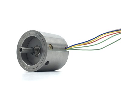 RVDT(Rotary Variable Differential Transformer) Basics
02 February 202117359
 Essential Tips for Picking the Best Gas Sensor
15 July 20251781
 Exploring an Advanced Approach to Thermal Design for Dual-Sided Cooling of Power Semiconductor Modules in Electric and Hybrid Vehicles
07 September 2023767
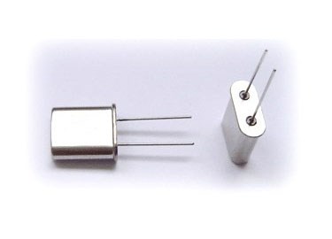 What are Resonators?
07 January 202615061
 What is OLED?
16 March 20215477
 Practical Ways to Use Common Mode Chokes in 2025
10 July 2025483
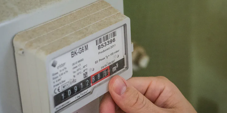
 How Many Types of Inverters are There?
28 March 202215781
 Electronic Components in the Smart Home System
24 April 20251100
Analog Devices, Inc.
In Stock: 2256
Minimum: 1 Multiples: 1
Qty
Unit Price
Ext Price
1
$123.343924
$123.34
10
$116.362192
$1,163.62
100
$109.775653
$10,977.57
500
$103.561937
$51,780.97
1000
$97.699941
$97,699.94
Not the price you want? Send RFQ Now and we'll contact you ASAP.
Inquire for More Quantity
![AD5362BSTZ]() AD5362BSTZ
AD5362BSTZAnalog Devices Inc.
![AD7524LPZ]() AD7524LPZ
AD7524LPZAnalog Devices Inc.
![AD5420AREZ-REEL7]() AD5420AREZ-REEL7
AD5420AREZ-REEL7Analog Devices Inc.
![AD5328BRUZ-REEL7]() AD5328BRUZ-REEL7
AD5328BRUZ-REEL7Analog Devices Inc.
![ADV7125JSTZ330]() ADV7125JSTZ330
ADV7125JSTZ330Analog Devices Inc.
![AD5324ARMZ-REEL7]() AD5324ARMZ-REEL7
AD5324ARMZ-REEL7Analog Devices Inc.
![AD420ANZ-32]() AD420ANZ-32
AD420ANZ-32Analog Devices Inc.
![AD5304ARMZ]() AD5304ARMZ
AD5304ARMZAnalog Devices Inc.
![AD5683RBRMZ-3-RL7]() AD5683RBRMZ-3-RL7
AD5683RBRMZ-3-RL7Analog Devices Inc.
![AD5601BKSZ-REEL7]() AD5601BKSZ-REEL7
AD5601BKSZ-REEL7Analog Devices Inc.


