
 Product
 Brand
Brand Articles
 Tools
Tools
DRV8833 two-channel H-bridge motor driver: How to use DRV8833?

2A mA 1.2mm mm 4.4mm mm Motor Drivers 16 5V V 5mm mm
Unit Price: $2.361123
Ext Price: $2.36


2A mA 1.2mm mm 4.4mm mm Motor Drivers 16 5V V 5mm mm
The DRV8833 is a two-channel H-bridge motor driver with two DC motors or one stepper motor. This article is going to talk about the features, pinout, applications, and more detailed information about the DRV8833.

Arduino RC Robot Car on a single PCB | Part 1 | DRV 8833 motor driver tutorial | Arduino Nano HC 05
Overview of DRV8833
The DRV8833 is a two-channel H-bridge motor driver with two DC motors or one stepper motor. Each output has inbuilt limiting, as well as protection against overcurrent, overtemperature, short-circuit, and under-voltage.
DRV8833 Features
Dual H-bridge current controlled motor driver
2A peak output current
Outputs can be paralleled
2.7V to 10.8V supply range
PWM current regulation
DRV8833 Pinout

DRV8833 Pinout
| Pin Number | Pin Name | Pin Description |
| 1 | SLEEP | Sleep mode input, active high |
| 2 | AOUT1 | Bridge A output 1 |
| 3 | AISEN | Bridge A ground/current sense |
| 4 | AOUT2 | Bridge A output 2 |
| 5 | BOUT2 | Bridge B output 2 |
| 6 | BISEN | Bridge B ground/current sense |
| 7 | BOUT1 | Bridge B output 1 |
| 8 | FAULT | Fault output, active low |
| 9 | BIN1 | Bridge B input 1 |
| 10 | BIN2 | Bridge B input 2 |
| 11 | VCP | High side gate drive |
| 12 | VM | Chip power supply |
| 13 | GND | Chip ground reference |
| 14 | VINT | Internal supply bypass |
| 15 | AIN2 | Bridge A input 2 |
| 16 | AIN1 | Bridge A input 1 |
Specifications
- TypeParameter
- Lifecycle Status
Lifecycle Status refers to the current stage of an electronic component in its product life cycle, indicating whether it is active, obsolete, or transitioning between these states. An active status means the component is in production and available for purchase. An obsolete status indicates that the component is no longer being manufactured or supported, and manufacturers typically provide a limited time frame for support. Understanding the lifecycle status is crucial for design engineers to ensure continuity and reliability in their projects.
ACTIVE (Last Updated: 5 days ago) - Factory Lead Time6 Weeks
- Mounting Type
The "Mounting Type" in electronic components refers to the method used to attach or connect a component to a circuit board or other substrate, such as through-hole, surface-mount, or panel mount.
Surface Mount - Package / Case
refers to the protective housing that encases an electronic component, providing mechanical support, electrical connections, and thermal management.
16-TSSOP (0.173, 4.40mm Width) - Surface Mount
having leads that are designed to be soldered on the side of a circuit board that the body of the component is mounted on.
YES - Number of Pins16
- Operating Temperature
The operating temperature is the range of ambient temperature within which a power supply, or any other electrical equipment, operate in. This ranges from a minimum operating temperature, to a peak or maximum operating temperature, outside which, the power supply may fail.
-40°C~150°C TJ - Packaging
Semiconductor package is a carrier / shell used to contain and cover one or more semiconductor components or integrated circuits. The material of the shell can be metal, plastic, glass or ceramic.
Tube - JESD-609 Code
The "JESD-609 Code" in electronic components refers to a standardized marking code that indicates the lead-free solder composition and finish of electronic components for compliance with environmental regulations.
e4 - Pbfree Code
The "Pbfree Code" parameter in electronic components refers to the code or marking used to indicate that the component is lead-free. Lead (Pb) is a toxic substance that has been widely used in electronic components for many years, but due to environmental concerns, there has been a shift towards lead-free alternatives. The Pbfree Code helps manufacturers and users easily identify components that do not contain lead, ensuring compliance with regulations and promoting environmentally friendly practices. It is important to pay attention to the Pbfree Code when selecting electronic components to ensure they meet the necessary requirements for lead-free applications.
yes - Part Status
Parts can have many statuses as they progress through the configuration, analysis, review, and approval stages.
Active - Moisture Sensitivity Level (MSL)
Moisture Sensitivity Level (MSL) is a standardized rating that indicates the susceptibility of electronic components, particularly semiconductors, to moisture-induced damage during storage and the soldering process, defining the allowable exposure time to ambient conditions before they require special handling or baking to prevent failures
3 (168 Hours) - Number of Terminations16
- Terminal Finish
Terminal Finish refers to the surface treatment applied to the terminals or leads of electronic components to enhance their performance and longevity. It can improve solderability, corrosion resistance, and overall reliability of the connection in electronic assemblies. Common finishes include nickel, gold, and tin, each possessing distinct properties suitable for various applications. The choice of terminal finish can significantly impact the durability and effectiveness of electronic devices.
Nickel/Palladium/Gold (Ni/Pd/Au) - Applications
The parameter "Applications" in electronic components refers to the specific uses or functions for which a component is designed. It encompasses various fields such as consumer electronics, industrial automation, telecommunications, automotive, and medical devices. Understanding the applications helps in selecting the right components for a particular design based on performance, reliability, and compatibility requirements. This parameter also guides manufacturers in targeting their products to relevant markets and customer needs.
DC Motors, General Purpose, Solenoids - HTS Code
HTS (Harmonized Tariff Schedule) codes are product classification codes between 8-1 digits. The first six digits are an HS code, and the countries of import assign the subsequent digits to provide additional classification. U.S. HTS codes are 1 digits and are administered by the U.S. International Trade Commission.
8542.39.00.01 - Voltage - Supply
Voltage - Supply refers to the range of voltage levels that an electronic component or circuit is designed to operate with. It indicates the minimum and maximum supply voltage that can be applied for the device to function properly. Providing supply voltages outside this range can lead to malfunction, damage, or reduced performance. This parameter is critical for ensuring compatibility between different components in a circuit.
2.7V~10.8V - Terminal Position
In electronic components, the term "Terminal Position" refers to the physical location of the connection points on the component where external electrical connections can be made. These connection points, known as terminals, are typically used to attach wires, leads, or other components to the main body of the electronic component. The terminal position is important for ensuring proper connectivity and functionality of the component within a circuit. It is often specified in technical datasheets or component specifications to help designers and engineers understand how to properly integrate the component into their circuit designs.
DUAL - Terminal Form
Occurring at or forming the end of a series, succession, or the like; closing; concluding.
GULL WING - Peak Reflow Temperature (Cel)
Peak Reflow Temperature (Cel) is a parameter that specifies the maximum temperature at which an electronic component can be exposed during the reflow soldering process. Reflow soldering is a common method used to attach electronic components to a circuit board. The Peak Reflow Temperature is crucial because it ensures that the component is not damaged or degraded during the soldering process. Exceeding the specified Peak Reflow Temperature can lead to issues such as component failure, reduced performance, or even permanent damage to the component. It is important for manufacturers and assemblers to adhere to the recommended Peak Reflow Temperature to ensure the reliability and functionality of the electronic components.
260 - Number of Functions1
- Supply Voltage
Supply voltage refers to the electrical potential difference provided to an electronic component or circuit. It is crucial for the proper operation of devices, as it powers their functions and determines performance characteristics. The supply voltage must be within specified limits to ensure reliability and prevent damage to components. Different electronic devices have specific supply voltage requirements, which can vary widely depending on their design and intended application.
5V - Time@Peak Reflow Temperature-Max (s)
Time@Peak Reflow Temperature-Max (s) refers to the maximum duration that an electronic component can be exposed to the peak reflow temperature during the soldering process, which is crucial for ensuring reliable solder joint formation without damaging the component.
NOT SPECIFIED - Base Part Number
The "Base Part Number" (BPN) in electronic components serves a similar purpose to the "Base Product Number." It refers to the primary identifier for a component that captures the essential characteristics shared by a group of similar components. The BPN provides a fundamental way to reference a family or series of components without specifying all the variations and specific details.
DRV8833 - Qualification Status
An indicator of formal certification of qualifications.
Not Qualified - Max Output Current
The maximum current that can be supplied to the load.
2A - Supply Voltage-Max (Vsup)
The parameter "Supply Voltage-Max (Vsup)" in electronic components refers to the maximum voltage that can be safely applied to the component without causing damage. It is an important specification to consider when designing or using electronic circuits to ensure the component operates within its safe operating limits. Exceeding the maximum supply voltage can lead to overheating, component failure, or even permanent damage. It is crucial to adhere to the specified maximum supply voltage to ensure the reliable and safe operation of the electronic component.
10.8V - Power Supplies
an electronic circuit that converts the voltage of an alternating current (AC) into a direct current (DC) voltage.?
3/10V - Supply Voltage-Min (Vsup)
The parameter "Supply Voltage-Min (Vsup)" in electronic components refers to the minimum voltage level required for the component to operate within its specified performance range. This parameter indicates the lowest voltage that can be safely applied to the component without risking damage or malfunction. It is crucial to ensure that the supply voltage provided to the component meets or exceeds this minimum value to ensure proper functionality and reliability. Failure to adhere to the specified minimum supply voltage may result in erratic behavior, reduced performance, or even permanent damage to the component.
2.7V - Interface
In electronic components, the term "Interface" refers to the point at which two different systems, devices, or components connect and interact with each other. It can involve physical connections such as ports, connectors, or cables, as well as communication protocols and standards that facilitate the exchange of data or signals between the connected entities. The interface serves as a bridge that enables seamless communication and interoperability between different parts of a system or between different systems altogether. Designing a reliable and efficient interface is crucial in ensuring proper functionality and performance of electronic components and systems.
PWM - Analog IC - Other Type
Analog IC - Other Type is a parameter used to categorize electronic components that are integrated circuits (ICs) designed for analog signal processing but do not fall into more specific subcategories such as amplifiers, comparators, or voltage regulators. These ICs may include specialized analog functions such as analog-to-digital converters (ADCs), digital-to-analog converters (DACs), voltage references, or signal conditioning circuits. They are typically used in various applications where precise analog signal processing is required, such as in audio equipment, instrumentation, communication systems, and industrial control systems. Manufacturers provide detailed specifications for these components to help engineers select the most suitable IC for their specific design requirements.
BRUSH DC MOTOR CONTROLLER - Output Configuration
Output Configuration in electronic components refers to the arrangement or setup of the output pins or terminals of a device. It defines how the output signals are structured and how they interact with external circuits or devices. The output configuration can determine the functionality and compatibility of the component in a circuit design. Common types of output configurations include single-ended, differential, open-drain, and push-pull configurations, each serving different purposes and applications in electronic systems. Understanding the output configuration of a component is crucial for proper integration and operation within a circuit.
Half Bridge (4) - Output Current
The rated output current is the maximum load current that a power supply can provide at a specified ambient temperature. A power supply can never provide more current that it's rated output current unless there is a fault, such as short circuit at the load.
500mA - Logic Function
In electronic components, the term "Logic Function" refers to the specific operation or behavior of a component based on its input signals. It describes how the component processes the input signals to produce the desired output. Logic functions are fundamental to digital circuits and are used to perform logical operations such as AND, OR, NOT, and XOR.Each electronic component, such as logic gates or flip-flops, is designed to perform a specific logic function based on its internal circuitry. By understanding the logic function of a component, engineers can design and analyze complex digital systems to ensure proper functionality and performance. Different logic functions can be combined to create more complex operations, allowing for the creation of sophisticated digital devices and systems.
AND - Output Current per Channel
Output Current per Channel is a specification commonly found in electronic components such as amplifiers, audio interfaces, and power supplies. It refers to the maximum amount of electrical current that can be delivered by each individual output channel of the component. This parameter is important because it determines the capacity of the component to drive connected devices or loads. A higher output current per channel means the component can deliver more power to connected devices, while a lower output current may limit the performance or functionality of the component in certain applications. It is crucial to consider the output current per channel when selecting electronic components to ensure they can meet the power requirements of the intended system or setup.
1.5A - Supply Current-Max (Isup)
Supply Current-Max (Isup) refers to the maximum amount of current that an electronic component can draw from its power supply during operation. It represents the peak current demand of the device under normal operating conditions and is critical for ensuring that the power supply can adequately support the component's needs without risking damage or malfunction. This parameter is essential for designing circuits and selecting appropriate power supply units to prevent overloading and ensure reliable performance.
3mA - Voltage - Load
Voltage - Load refers to the voltage across a load component in an electronic circuit when it is connected and operational. It represents the electrical potential difference that drives current through the load, which can be a resistor, motor, or other devices that consume electrical power. The voltage - load relationship is crucial for determining how much power the load will utilize and how it will affect the overall circuit performance. Properly managing voltage - load is essential for ensuring devices operate efficiently and safely within their specified limits.
2.7V~10.8V - RMS Current (Irms)
RMS Current (Irms) refers to the Root Mean Square value of the alternating current flowing through an electronic component or circuit. It is a measure of the effective current that produces the same heating effect as the equivalent DC current. In AC circuits, the current continuously changes direction, so using the RMS value helps in calculating power dissipation and determining the component's capability to handle the current without overheating. RMS Current is crucial in selecting components like resistors, capacitors, and inductors to ensure they can safely operate within their specified current ratings.
1.5A - Height1.2mm
- Length5mm
- Width4.4mm
- Thickness
Thickness in electronic components refers to the measurement of how thick a particular material or layer is within the component structure. It can pertain to various aspects, such as the thickness of a substrate, a dielectric layer, or conductive traces. This parameter is crucial as it impacts the electrical, mechanical, and thermal properties of the component, influencing its performance and reliability in electronic circuits.
1mm - RoHS Status
RoHS means “Restriction of Certain Hazardous Substances” in the “Hazardous Substances Directive” in electrical and electronic equipment.
ROHS3 Compliant - Lead Free
Lead Free is a term used to describe electronic components that do not contain lead as part of their composition. Lead is a toxic material that can have harmful effects on human health and the environment, so the electronics industry has been moving towards lead-free components to reduce these risks. Lead-free components are typically made using alternative materials such as silver, copper, and tin. Manufacturers must comply with regulations such as the Restriction of Hazardous Substances (RoHS) directive to ensure that their products are lead-free and environmentally friendly.
Lead Free
DRV8833 CAD Model

DRV8833 Symbol

DRV8833 Footprint
DRV8833 Circuit Diagram

DRV8833 Circuit Diagram
DRV8833 Equivalents
Parts with Similar Specs
- ImagePart NumberManufacturerPackage / CaseNumber of PinsLogic FunctionInterfaceSupply VoltagePbfree CodeLengthLead FreeView Compare
![DRV8833PW]()
DRV8833PW
16-TSSOP (0.173, 4.40mm Width)
16
AND
PWM
5 V
yes
5 mm
Lead Free
![SN74LVC112APWR]()
16-TSSOP (0.173, 4.40mm Width)
16
AND, Flip-Flop, JK-Type
-
4.5 V
yes
5 mm
Lead Free
![DRV777PWR]()
16-TSSOP (0.173, 4.40mm Width)
16
AND, JK-Type
-
5 V
yes
5 mm
Lead Free
![CD74HC112PWR]()
16-TSSOP (0.173, 4.40mm Width)
16
AND, Flip-Flop, JK-Type
-
1.8 V
yes
5 mm
Lead Free
![MC74HC112ADTG]()
16-TSSOP (0.173, 4.40mm Width)
16
AND
Parallel
3.3 V
yes
5 mm
Lead Free


How to use the DRV8833?
The DRV8833 is a two-channel H-bridge motor driver with the ability to operate two DC motors or one stepper motor. It includes internal overcurrent protection and can supply up to 2A peak current. The circuit schematic for the DRV8833 dual DC motor controller is shown below.

The AIN1/2 and BIN1/2 pins are used to regulate the motors. Only the direction of the motor can be controlled, not its speed. The functions provided by each pin state are listed in the table below.
| AIN1/BIN1 | AIN2/BIN2 | |
| Forward | HIGH | LOW |
| Reverse | LOW | HIGH |
| Brake/Stop | LOW | LOW |
| Brake/Stop | HIGH | HIGH |
DRV8833 Applications
Battery-powered toys
POS printers
Security cameras
Gaming machines
Robotics
Popularity by Region
What is H-bridge circuit?
The H-bridge is an electrical circuit in the shape of an H. An H-bridge is used to drive a load in both directions, such as a brushed DC motor. It also regulates the flow of current to a load.
What is dual H-bridge motor driver?
DRV8833 Dual H Bridge Motor Driver is a motor controller breakout board that is typically used for controlling the speed and direction of motors. It can also be used to control the brightness of certain lighting projects such as high powered LED arrays.
What is the DRV8833?
The DRV8833 is a two-channel H-bridge motor driver with two DC motors or one stepper motor.
 MPX2010DP Pressure Sensor: MPX2010DP Datasheet and Block Diagram
28 March 20224370
 STM32L021K4T6 Ultra-Low-Power 32-bit MCU: Datasheet Analysis
29 February 2024193
 LM2576T Regulator: Circuit, Pinout, and Datasheet
03 December 202119129
![BC549 Bipolar Transistor[FAQ+Video]:Pinout, datasheet, and Circuit](https://res.utmel.com/Images/Article/85e6f679-fe57-40e8-a861-11d4f28c37ee.jpg) BC549 Bipolar Transistor[FAQ+Video]:Pinout, datasheet, and Circuit
BC549 Bipolar Transistor[FAQ+Video]:Pinout, datasheet, and Circuit06 April 20224564
![S9014 Transistor: Pinout, Datasheet and Circuit [Video&FAQ]](https://res.utmel.com/Images/Article/b4d58d10-6f12-40f3-a348-8439a1be6520.png) S9014 Transistor: Pinout, Datasheet and Circuit [Video&FAQ]
S9014 Transistor: Pinout, Datasheet and Circuit [Video&FAQ]28 September 202146913
 ADA4622-4 Precision Op-Amp: Features, Pinout and Datasheet
13 December 20211342
 A Comprehensive Guide to the RV-8803 Real-Time Clock Module
11 March 20241959
 Vicor Corporation PI3740-00-LGIZ Purchase Checklist
16 August 2025269
 Silicon Carbide Semiconductor Devices at Ultra-high Voltages and their Applications
04 January 20232008
 Difference between Various Motors and How to Select a Motor?
10 January 20224841
 Introduction to Tantalum Capacitors
16 October 202512691
 0 Ohm Resistor Explained
10 December 202119674
 What is Amplifier?
08 November 20257941
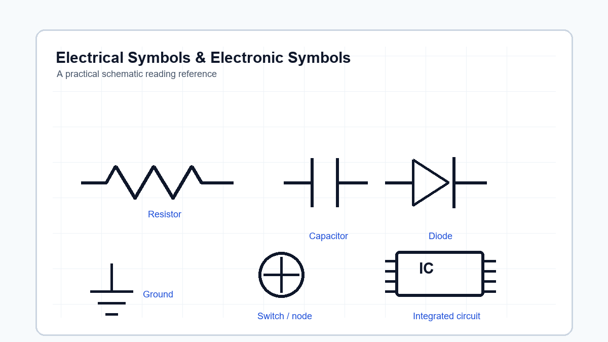 Electrical Symbols & Electronic Symbols: A Practical Guide to Reading Circuit Diagrams
17 June 2026170
 What is Digital Power Supply?
10 November 20203384
 LDO VS DC to DC Converter
11 March 202211632
Texas Instruments
In Stock: 9
Minimum: 1 Multiples: 1
Qty
Unit Price
Ext Price
1
$2.361123
$2.36
10
$2.227475
$22.27
100
$2.101391
$210.14
500
$1.982444
$991.22
1000
$1.870231
$1,870.23
Not the price you want? Send RFQ Now and we'll contact you ASAP.
Inquire for More Quantity
![LMD18201T/NOPB]() LMD18201T/NOPB
LMD18201T/NOPBTexas Instruments
![DRV8833PWPR]() DRV8833PWPR
DRV8833PWPRTexas Instruments
![DRV8302DCAR]() DRV8302DCAR
DRV8302DCARTexas Instruments
![LMD18200T/NOPB]() LMD18200T/NOPB
LMD18200T/NOPBTexas Instruments
![DRV8824PWPR]() DRV8824PWPR
DRV8824PWPRTexas Instruments
![DRV8848PWP]() DRV8848PWP
DRV8848PWPTexas Instruments
![DRV8301DCAR]() DRV8301DCAR
DRV8301DCARTexas Instruments
![UC3638DW]() UC3638DW
UC3638DWTexas Instruments
![UC2625DW]() UC2625DW
UC2625DWTexas Instruments
![L293NE]() L293NE
L293NETexas Instruments


