

 Product
 Brand
 Articles
 Tools

LT1054 100mA Switched-Capacitor Voltage Converter: Datasheet, Pinout, and Design Analysis

Linear Technology/Analog Devices
8 Terminals 3.5V LT1054 DC DC Voltage Regulator SWITCHED CAPACITOR REGULATOR 1 Outputs 25kHz Tube 100mA 8-DIP (0.300, 7.62mm)
Unit Price: $11.564371
Ext Price: $11.56


8 Terminals 3.5V LT1054 DC DC Voltage Regulator SWITCHED CAPACITOR REGULATOR 1 Outputs 25kHz Tube 100mA 8-DIP (0.300, 7.62mm)
Optimize your BOM with the LT1054 100mA voltage converter. Explore pinout, 3.5V-15V specs, and latch-up solutions for stable split-rail power designs.
- Executive Summary: What is the LT1054?
- 1. Technical Specifications & Performance Analysis
- 2. Pinout, Package, and Configuration
- 3. Design & Integration Guide
- 4. Typical Applications & Use Cases
- 5. Alternatives and Cross-Reference Guide
- 6. Frequently Asked Questions (FAQ)
- 7. Resources
- Specifications
- Datasheet PDF
Executive Summary: What is the LT1054?
The LT1054 is a monolithic, bipolar, switched-capacitor voltage converter and regulator designed to provide significantly higher output current and lower voltage losses than the industry-standard ICL7660. It serves as a versatile power management solution for generating negative supply rails or doubling voltages without the need for bulky inductors.
Market Position: High-performance, high-current alternative to standard charge pumps; widely considered the "gold standard" for 100mA negative rail generation.
Top Features: 100mA output current, wide 3.5V to 15V input range, and integrated voltage regulation.
Primary Audience: Analog design engineers requiring split-rail supplies for op-amps and procurement managers seeking a reliable, long-lifecycle component.
Supply Status: Active (Manufactured by Analog Devices / Linear Technology).
1. Technical Specifications & Performance Analysis
1.1 Core Architecture (Charge Pump)
The LT1054 utilizes a switched-capacitor (charge pump) topology. Unlike basic converters, it features an adaptive switch driver scheme. This architecture optimizes efficiency by sensing the load current and adjusting the gate drive to the internal power switches, minimizing "voltage droop" which is a common failure point in cheaper charge pumps.
1.2 Key Electrical Characteristics
For engineers and buyers, the LT1054 stands out due to its ruggedness and power density:
Input Voltage Range: 3.5V to 15V, making it compatible with standard 5V, 9V, and 12V logic rails.
Max Output Current: 100mA, which is roughly 5x the capability of the ICL7660.
Low Voltage Loss: Only 1.1V loss at 100mA load, ensuring high efficiency in battery-powered applications.
Quiescent Current: A modest 2.5mA, balancing performance with power conservation.
1.3 Interfaces and Connectivity
While the LT1054 is an analog power device, it provides several control pins for system integration:
OSC Pin: Allows for external oscillator synchronization to prevent EMI interference with sensitive audio or RF circuits.
SHDN Pin: Supports an external shutdown mode to reduce power consumption in "sleep" states.
FB (Feedback): Used with the internal error amplifier to create a regulated output.
2. Pinout, Package, and Configuration
2.1 Pin Configuration Guide
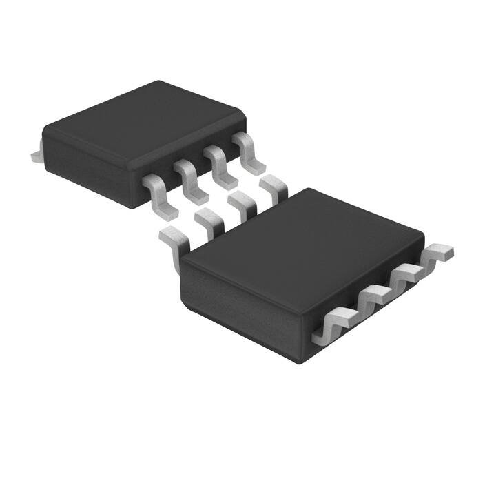
The LT1054 is most commonly found in 8-pin configurations.
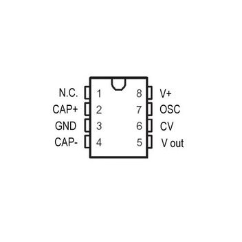
Pin 1 (Reference/NC): Used for the internal voltage reference. Note: This is NOT a boost pin like on the ICL7660.
Pin 2 (CAP+): Connection for the positive terminal of the "flying" charge pump capacitor.
Pin 3 (GND): System ground.
Pin 4 (CAP-): Connection for the negative terminal of the flying capacitor.
Pin 5 (Vout): The converted output voltage (usually negative).
Pin 6 (Vref): Reference output for regulation.
Pin 7 (OSC): Oscillator control input.
Pin 8 (Vin): Positive supply voltage input.
2.2 Naming Convention & Ordering Codes
Understanding the suffixes is vital for procurement:
LT1054CN8: Commercial temperature range (0°C to 70°C), 8-pin PDIP.
LT1054IS8: Industrial temperature range (-40°C to 85°C), 8-pin SOIC.
LT1054CSW: 16-pin Wide SOIC (better thermal dissipation).
2.3 Available Packages
| Package Type | Dimensions | Common Use Case |
|---|---|---|
| PDIP-8 | 9.27mm x 6.35mm | Prototyping, through-hole hobbyist boards. |
| SOIC-8 | 4.90mm x 3.91mm | Standard surface-mount industrial PCBs. |
| SOIC-16 (Wide) | 10.3mm x 7.5mm | High-power applications requiring better thermals. |
3. Design & Integration Guide
3.1 Hardware Implementation
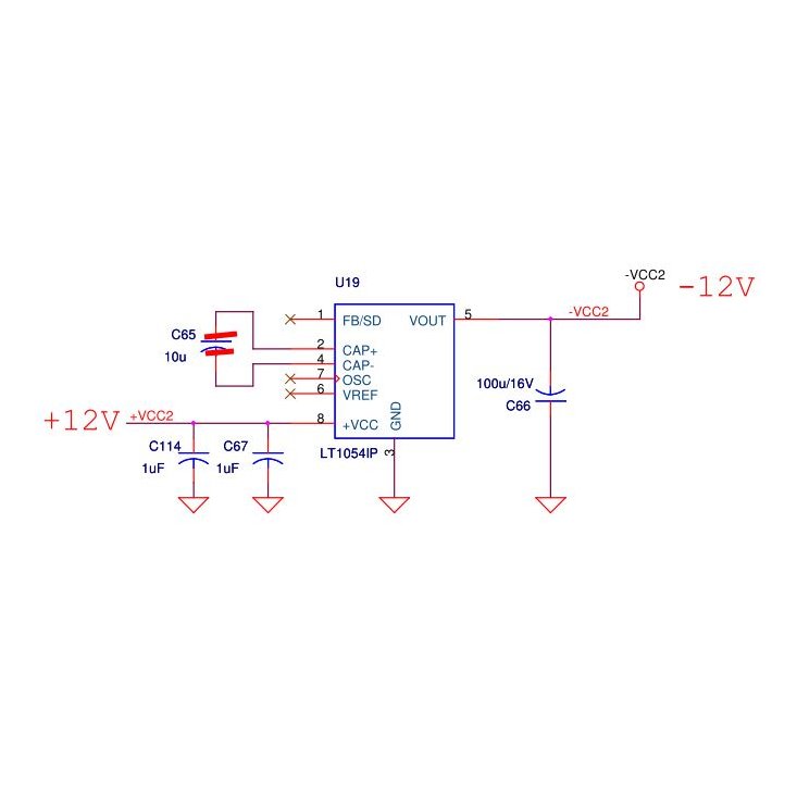
Bypass Capacitors: Use low-ESR tantalum or ceramic capacitors. A value of 10µF to 100µF is typically recommended for both the flying capacitor and the output reservoir capacitor.
PCB Layout: Keep the flying capacitor traces as short as possible to minimize radiated EMI and parasitic inductance.
Thermal Management: At a full 100mA load and 15V input, the device can generate heat. Ensure adequate copper pour around the GND pins for heat sinking.
3.2 Common Design Challenges
Issue: Startup Latch-Up: If the output is pulled above ground during power-up, the device may hang.
Fix: Place a 1N5817 Schottky diode from Vout to Ground (Anode to Vout).
Issue: Pin 1 Compatibility: Designers replacing an ICL7660 often mistakenly connect Pin 1 to Vin for "Boost" mode.
Fix: Leave Pin 1 open or use it only for regulation as per the LT1054 datasheet.
4. Typical Applications & Use Cases
4.1 Real-World Example: Negative Rail for Op-Amps
In high-fidelity audio or precision measurement equipment, op-amps often require a bipolar supply (e.g., ±5V). If the system only has a +5V USB input, the LT1054 acts as an Inverter. It converts the +5V into a -5V rail with enough current (100mA) to power multiple high-performance op-amps simultaneously without significant voltage sag.
5. Alternatives and Cross-Reference Guide
Direct Replacements: The LTC1044 and ICL7660 are pin-compatible but offer significantly lower current (typically 10-20mA). Use the LT1054 as an "upgrade" for these parts.
High-Frequency Alternative: The LM2660 (Texas Instruments) offers higher switching frequencies (up to 80kHz), which allows for smaller capacitors, though the LT1054 generally offers better regulation features.
Cost-Effective Options: For very low-current applications (<10mA), the TC1044S is a budget-friendly alternative.
6. Frequently Asked Questions (FAQ)
Q: What is the difference between LT1054 and ICL7660?A: The LT1054 supports 100mA (vs 20mA), has a higher input voltage (15V vs 10V), and includes an internal regulator.
Q: Can LT1054 be used for voltage doubling?A: Yes, by reconfiguring the external capacitors, the LT1054 can function as a positive or negative voltage doubler.
Q: Why is my LT1054 getting hot?A: This usually occurs if the output current exceeds 100mA or if the output capacitor has excessively high ESR. Check your load and component specs.
Q: Is the LT1054 suitable for battery-operated devices?A: Yes, especially because its low voltage loss (1.1V) ensures you get the most usable energy out of your battery rail.
7. Resources
Datasheet: Search "Analog Devices LT1054 Datasheet" for the latest PDF version.
Simulation Tools: LTspice models are available for accurate power behavior simulation.
Specifications
Datasheet PDF
- Datasheets :
- Simulation Models :
 MPL3115A2 Pressure Sensor: Datasheet, Pinout and Schematic
25 August 20213353
 Enhancing Server Efficiency with BCM957412A4120AC Setup Tips
15 July 2025326
 AD827SQ Operational Amplifier: Feature, Specification, Datasheet
24 May 20211507
 AT45DB321E SPI Serial Flash Memory: Pinout, Features and Datasheet
11 January 20222828
 2SB772 Transistor: Datasheet, Equivalent, Pinout
25 October 202110675
 TL084 JFET-Input Operational Amplifier Design Guide and Architecture Analysis
19 January 20261958
 XC6SLX150T-3FGG676I vs XC6SLX150-2FGG900I 2025 FPGA Comparison Guide
07 June 2025327
 The Comprehensive Introduction to Si53306
16 June 20221660
 RF Front End in the 5G Era
25 October 20217928
 Breakout Boards Alternatives for Your Next Home Project
02 July 20252664
 Introduction to Centrifugal Switch
27 January 202114644
 Silicon Carbide (SiC): The Third-generation Semiconductor Material
30 August 202110291
 What is 3D Printing Technology (3DP)?
18 January 20224587
 Introduction to USB Type-C
20 February 20232883
 Silicon Carbide Semiconductor Devices at Ultra-high Voltages and their Applications
04 January 20232214
 Power Semiconductor Procurement After the Nexperia Shake-Up—NXP for Stability, ON for Technology, or Nexperia for Value?
04 November 20255007
Linear Technology/Analog Devices
In Stock: 2
Minimum: 1 Multiples: 1
Qty
Unit Price
Ext Price
1
$11.564371
$11.56
10
$10.909784
$109.10
100
$10.292249
$1,029.22
500
$9.709669
$4,854.83
1000
$9.160065
$9,160.06
Not the price you want? Send RFQ Now and we'll contact you ASAP.
Inquire for More Quantity
![LTC1624CS8#PBF]() LTC1624CS8#PBF
AnalogDevices
![LT8609EMSE#TRPBF]() LT8609EMSE#TRPBF
Linear Technology/Analog Devices
![LT1933ES6#TRPBF]() LT1933ES6#TRPBF
Linear Technology/Analog Devices
![LT1054IS8#TRPBF]() LT1054IS8#TRPBF
Linear Technology/Analog Devices
![ADP1613ARMZ-R7]() ADP1613ARMZ-R7
Analog Devices Inc.
![LT1933ES6#TRMPBF]() LT1933ES6#TRMPBF
Linear Technology/Analog Devices
![ADM660ARZ]() ADM660ARZ
Analog Devices Inc.
![LT8609SIV#PBF]() LT8609SIV#PBF
Linear Technology/Analog Devices
![LT1376HVCS8#PBF]() LT1376HVCS8#PBF
Linear Technology/Analog Devices
![LT3508EFE#PBF]() LT3508EFE#PBF
Linear Technology/Analog Devices


