
 Product
 Brand
Brand Articles
 Tools
Tools
TL084 JFET-Input Operational Amplifier Design Guide and Architecture Analysis


30pA Instrumentational OP Amps 7V~36V ±3.5V~18V TL084 14-DIP (0.300, 7.62mm)
The TL084 is a quad JFET-input op-amp featuring a 13 V/µs slew rate and 30 pA input bias current. This guide covers datasheet specs, PCB layout strategies, and phase reversal fixes.
Takeaway
Positioning: The TL084 serves as the industry-standard "workhorse" for high-impedance signal conditioning. It bridges the gap between general-purpose bipolar op-amps (like the LM324) and precision instrumentation amplifiers by utilizing a JFET-input stage.
Key Spec Highlight: 13 V/µs Slew Rate (typical), allowing for superior transient response in high-speed audio and pulse applications compared to standard generic op-amps.
Supply Chain Status: Active and widely available. This is a high-volume part with multiple sourcing options (TI, ST, ON Semi), making it "Maker-friendly" and low-risk for long-term designs.
1. Technical Architecture and Core Advantages
The TL084 is a high-speed, quad operational amplifier. Its defining architectural feature is the integration of high-voltage JFET and bipolar transistors on a single monolithic integrated circuit. This hybrid topology provides the high input impedance of JFETs with the drive capability of bipolar outputs.
1.1 Processing & Control (The "Brain")
At the silicon level, the TL084 relies on a JFET-Input Stage.
JFET Advantage: Unlike BJT-input op-amps that draw significant bias current (nanoamps or microamps), the TL084 draws a typical Input Bias Current of just 30 pA. This architecture minimizes loading effects on high-source-impedance sensors (e.g., pH probes, piezo elements).
Slew Rate Logic: The internal frequency compensation is tuned for a high slew rate (13 V/µs), enabling the "brain" of the chip to track rapidly changing input signals without distortion, a critical factor in active filters and audio pre-amps.
1.2 Peripherals & Interfaces (The "Limbs")
The TL084 operates as a Quad package, meaning it houses four independent operational amplifiers sharing a common power rail. - Package Density: Available in 14-pin DIP, SOIC, and TSSOP, allowing four signal chains to be processed in a small footprint. - Input/Output Range: - Inputs: High impedance (JFET).
Outputs: Short-circuit protected.
Bandwidth: 3 MHz Gain Bandwidth Product (GBW).
2. Naming / Variant Map and Selection Guide
2.1 Part Number Decoding
The specific suffix determines the offset precision, temperature range, and package type.
Prefix (TL): Texas Instruments Linear series.
Number (084): Quad JFET Op-Amp (Compare to 081 for Single, 082 for Dual).
Suffix Letter 1 (Precision/Type):
No Letter: Standard Grade.
A: Improved Input Offset Voltage.
B: Best Input Offset Voltage.
H: High-Voltage / Phase-Reversal Resistant.
Suffix Letter 2 (Temperature):
C: Commercial (0°C to 70°C).
I: Industrial (-40°C to 85°C).
M: Military (-55°C to 125°C).
Package Code:
N: PDIP-14 (Through-hole).
D: SOIC-14 (Surface mount).
PW: TSSOP-14 (Thin surface mount).
2.2 Core Variant Comparison
| Variant | Key Differences | Offset Voltage (Max) | Target Use |
|---|---|---|---|
| TL084C | Standard commercial grade | 15 mV | General Purpose Audio/Logic |
| TL084BC | High precision offset | 3 mV | Precision Instrumentation |
| TL084I | Industrial Temp Range | 6 mV | Outdoor/Industrial Sensors |
| TL084H | High Spec / Robustness | Variable | High-reliability Automotive/Industrial |
3. Key Specifications Explained
Engineer's Note: Values below are typical at 25°C. Always consult the specific datasheet for manufacturing limit values (min/max).
3.1 Power & Operating Conditions
Supply Voltage (Max): ±18 V. The device is designed for dual-supply operation (e.g., +12V/-12V or +15V/-15V). While single-supply operation is possible with virtual ground biasing, performance is optimal with split rails.
Power Consumption: Low power consumption relative to bandwidth, but higher than modern CMOS rail-to-rail op-amps.
3.2 Performance & Efficiency
Slew Rate: 13 V/µs. This is the metric that separates the TL084 from the LM324 (which is ~0.5 V/µs). It determines the maximum frequency at which the op-amp can output a large signal without turning it into a triangle wave.
Input Bias Current: 30 pA. Critical for "High-Z" sensor interfaces.
Gain Bandwidth Product (GBP): 3 MHz. Suitable for audio frequencies and IF signal processing.
4. Design Notes and Common Integration Issues
4.1 PCB Layout Guidelines
Proper layout is essential to maintain the low-bias performance of the JFET inputs. - Power Rails: Place 0.1µF ceramic decoupling capacitors as close as possible to VCC+ and VCC-. Parasitic inductance on supply lines can cause oscillation. - Leakage Control: Because input bias is only 30 pA, PCB leakage currents (caused by flux residue or humidity) can overwhelm the signal. Use Guard Rings around the input pins connected to a low-impedance node at the same potential as the inputs to shunt leakage away. - Thermal: Standard copper pours are usually sufficient for PDIP/SOIC packages unless driving low-impedance loads continuously.

TL084 pinout diagram and footprint
4.2 Debugging Common Faults (Pain Points)
Problem 1: Phase Reversal- Symptom: The output suddenly flips to the opposite supply rail when the input signal goes near the negative supply rail.
- Root Cause: Exceeding the input common-mode voltage range (specifically the negative limit).
Fix: Ensure inputs stay within the datasheet Common-Mode Voltage Range (typically Vcc- + 4V). Alternatively, swap to the TL084H variant, which acts as a drop-in replacement designed to suppress phase reversal.
Problem 2: High Frequency Oscillation (~4 MHz)- Symptom: Unexplained noise or circuit instability.
- Root Cause: Often due to capacitive loading on the output or lack of decoupling.
- Fix: Isolate large capacitive loads with a small series resistor (10-50 Ohms). Ensure 0.1µF bypass capacitors are physically close to the power pins.
Problem 3: Environmental Drift- Symptom: Offset voltage shifts in humid or cold environments.
Root Cause: Micro-condensation affecting high-impedance JFET inputs.
Fix: Apply conformal coating to the PCB section containing the TL084 inputs. Select "I" (Industrial) suffix parts for better thermal stability.
5. Typical Applications
5.1 System Integration Analysis
Primary Application: Analog Active FiltersActive filters require op-amps with high impedance (to not load the RC network) and high slew rate (to maintain filter linearity at higher frequencies).
Why TL084? The 10^12 Ω input impedance ensures that the values of resistors and capacitors in the filter network determine the frequency response, not the op-amp's input characteristics. The 13 V/µs slew rate allows the filter to handle sharp transient spikes without distortion.

TL084 typical application circuit schematic
6. Competitors and Alternatives
The TL084 faces competition from both legacy and modern equivalents.
Vs. LF347 (National/TI): The LF347 is the direct JFET-input competitor. Specs are nearly identical. Selection often comes down to stock availability and price.
Vs. TL074: The TL074 is the "Low Noise" version of the TL084 series. If your design is a sensitive audio pre-amp, TL074 is generally preferred (lower noise floor). For general control and industrial drive, TL084 is standard.
Vs. LM324: The LM324 is Bipolar, slower (0.5 V/µs), but runs easily on a single supply. Choose TL084 for speed; choose LM324 for simple, low-speed, single-supply tasks.
7. FAQ
Q: What is the absolute maximum supply voltage for the TL084?
The absolute maximum supply voltage is ±18 V, meaning a total differential voltage of 36 V between VCC+ and VCC-.
Q: Does the TL084 support rail-to-rail output?
No, the TL084 is a legacy split-supply op-amp; its output swing usually stops 1.5V to 3V away from the power rails.
Q: What is the main difference between TL084 and TL084A?
The "A" variant offers tighter Input Offset Voltage specifications (6 mV max vs. 15 mV max for standard), providing better accuracy in DC applications.
Q: Can I use the TL084 with a single power supply?
Yes, but you must bias the inputs to a "virtual ground" (usually half the supply voltage) for it to function correctly for AC signals.
Q: Why does my TL084 circuit oscillate?
Oscillation is most commonly caused by missing 0.1µF ceramic decoupling capacitors on the power pins or driving a high-capacitance load directly.
8. Resources and Downloads
Datasheet: TL084 Datasheet (Texas Instruments)
Dev Tools: Breadboard-friendly DIP-14 packages are widely available for prototyping.
Specifications
Parts with Similar Specs
- ImagePart NumberManufacturerPackage / CaseNumber of PinsNumber of CircuitsSlew RateMoisture Sensitivity Level (MSL)Mounting TypePackagingView Compare
![TL084ING4]()
TL084ING4
14-DIP (0.300, 7.62mm)
14
4
13V/μs
1 (Unlimited)
Through Hole
Tube
![LM2902N]()
14-DIP (0.300, 7.62mm)
14
4
10 V/μs
1 (Unlimited)
Through Hole
Tube
![TL074CN]()
14-DIP (0.300, 7.62mm)
14
-
13V/μs
1 (Unlimited)
Through Hole
Tube
![LM324N]()
14-DIP (0.300, 7.62mm)
14
4
0.3 V/μs
1 (Unlimited)
Through Hole
Tube
![KA324]()
14-DIP (0.300, 7.62mm)
14
4
0.6 V/μs
1 (Unlimited)
Through Hole
Tube

 Everything You Need to Know About TL494 Current-Mode PWM Controller
19 April 202211885
 Mastering the RF Agile Transceiver: 70 MHz to 6.0 GHz SDR Performance and Design Solutions
12 February 2026452
 STM32F030K6T6: Features, Pinout and Datasheet
18 October 20235839
![BAT30F4 Schottky Diode: BAT30F4 Datasheet, Pinout, Application [FAQ]](https://res.utmel.com/Images/Article/288ae1e0-8161-4043-badc-23daa9f4a05b.jpg) BAT30F4 Schottky Diode: BAT30F4 Datasheet, Pinout, Application [FAQ]
BAT30F4 Schottky Diode: BAT30F4 Datasheet, Pinout, Application [FAQ]20 April 2022746
 MAX3243IPW Transceiver: Pinout,Specification, and Datasheet
06 July 2021711
![SIM800L VS SIM900A[Video&FAQ]: How to differentiate them?](https://res.utmel.com/Images/Article/16cc6f69-fe9d-4df2-ad71-8e029ce278af.png) SIM800L VS SIM900A[Video&FAQ]: How to differentiate them?
SIM800L VS SIM900A[Video&FAQ]: How to differentiate them?28 April 202218881
 PIC16F876 Microcontroller: Features, Pinout, and Datasheet
23 November 20218159
 SiM3C154B/GM 32-bit ARM Cortex-M3 Microcontroller: Technical Overview and Applications
29 February 2024204
 JSCJ Authorized Distributor | UTMEL Electronics
21 November 20234185
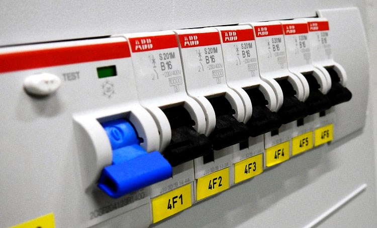 Circuit Breaker: Working Principle, Types and Structure
21 November 202511579
 An Overview of Bipolar Transistors
27 August 20208998
 15 Key Elements of Diode Selection
26 November 202118824
 What is 3D Printing Technology (3DP)?
18 January 20224124
 What is Bluetooth Low Energy (BLE) Audio Technology?
26 April 20226973
 Trimmer Resistors: From Principles to Selection and Applications
11 August 20253327
 MEMS Basics: System Features and Classifications
11 June 20217296
Texas Instruments
In Stock
United States
China
Canada
Japan
Russia
Germany
United Kingdom
Singapore
Italy
Hong Kong(China)
Taiwan(China)
France
Korea
Mexico
Netherlands
Malaysia
Austria
Spain
Switzerland
Poland
Thailand
Vietnam
India
United Arab Emirates
Afghanistan
Åland Islands
Albania
Algeria
American Samoa
Andorra
Angola
Anguilla
Antigua & Barbuda
Argentina
Armenia
Aruba
Australia
Azerbaijan
Bahamas
Bahrain
Bangladesh
Barbados
Belarus
Belgium
Belize
Benin
Bermuda
Bhutan
Bolivia
Bonaire, Sint Eustatius and Saba
Bosnia & Herzegovina
Botswana
Brazil
British Indian Ocean Territory
British Virgin Islands
Brunei
Bulgaria
Burkina Faso
Burundi
Cabo Verde
Cambodia
Cameroon
Cayman Islands
Central African Republic
Chad
Chile
Christmas Island
Cocos (Keeling) Islands
Colombia
Comoros
Congo
Congo (DRC)
Cook Islands
Costa Rica
Côte d’Ivoire
Croatia
Cuba
Curaçao
Cyprus
Czechia
Denmark
Djibouti
Dominica
Dominican Republic
Ecuador
Egypt
El Salvador
Equatorial Guinea
Eritrea
Estonia
Eswatini
Ethiopia
Falkland Islands
Faroe Islands
Fiji
Finland
French Guiana
French Polynesia
Gabon
Gambia
Georgia
Ghana
Gibraltar
Greece
Greenland
Grenada
Guadeloupe
Guam
Guatemala
Guernsey
Guinea
Guinea-Bissau
Guyana
Haiti
Honduras
Hungary
Iceland
Indonesia
Iran
Iraq
Ireland
Isle of Man
Israel
Jamaica
Jersey
Jordan
Kazakhstan
Kenya
Kiribati
Kosovo
Kuwait
Kyrgyzstan
Laos
Latvia
Lebanon
Lesotho
Liberia
Libya
Liechtenstein
Lithuania
Luxembourg
Macao(China)
Madagascar
Malawi
Maldives
Mali
Malta
Marshall Islands
Martinique
Mauritania
Mauritius
Mayotte
Micronesia
Moldova
Monaco
Mongolia
Montenegro
Montserrat
Morocco
Mozambique
Myanmar
Namibia
Nauru
Nepal
New Caledonia
New Zealand
Nicaragua
Niger
Nigeria
Niue
Norfolk Island
North Korea
North Macedonia
Northern Mariana Islands
Norway
Oman
Pakistan
Palau
Palestinian Authority
Panama
Papua New Guinea
Paraguay
Peru
Philippines
Pitcairn Islands
Portugal
Puerto Rico
Qatar
Réunion
Romania
Rwanda
Samoa
San Marino
São Tomé & Príncipe
Saudi Arabia
Senegal
Serbia
Seychelles
Sierra Leone
Sint Maarten
Slovakia
Slovenia
Solomon Islands
Somalia
South Africa
South Sudan
Sri Lanka
St Helena, Ascension, Tristan da Cunha
St. Barthélemy
St. Kitts & Nevis
St. Lucia
St. Martin
St. Pierre & Miquelon
St. Vincent & Grenadines
Sudan
Suriname
Svalbard & Jan Mayen
Sweden
Syria
Tajikistan
Tanzania
Timor-Leste
Togo
Tokelau
Tonga
Trinidad & Tobago
Tunisia
Turkey
Turkmenistan
Turks & Caicos Islands
Tuvalu
U.S. Outlying Islands
U.S. Virgin Islands
Uganda
Ukraine
Uruguay
Uzbekistan
Vanuatu
Vatican City
Venezuela
Wallis & Futuna
Yemen
Zambia
Zimbabwe
![LMV722MX]() LMV722MX
LMV722MXTexas Instruments
![LMC6082AIN]() LMC6082AIN
LMC6082AINTexas Instruments
![RC4558P]() RC4558P
RC4558PTexas Instruments
![LMC6482IMM/NOPB]() LMC6482IMM/NOPB
LMC6482IMM/NOPBTexas Instruments
![LM324MX/NOPB]() LM324MX/NOPB
LM324MX/NOPBTexas Instruments
![LM324AM/NOPB]() LM324AM/NOPB
LM324AM/NOPBTexas Instruments
![LMV324IDR]() LMV324IDR
LMV324IDRTexas Instruments
![LMC7101BIM5/NOPB]() LMC7101BIM5/NOPB
LMC7101BIM5/NOPBTexas Instruments
![TLV2372IDR]() TLV2372IDR
TLV2372IDRTexas Instruments
![NE5532P]() NE5532P
NE5532PTexas Instruments


