
PIC12F508 Microcontroller: Datasheet, Programming, Block Diagram

768B 512 x 12 FLASH PIC 8-Bit Microcontroller PIC® 12F Series PIC12F508 8 Pin 4MHz 2.5V 8-DIP (0.300, 7.62mm)


768B 512 x 12 FLASH PIC 8-Bit Microcontroller PIC® 12F Series PIC12F508 8 Pin 4MHz 2.5V 8-DIP (0.300, 7.62mm)
PIC12F508 is a low-cost, high-performance, 8-bit, fully-static, Flash-based CMOS Microcontroller. This article will unlock more details about PIC12F508. And more, Huge range of Semiconductors, Capacitors, Resistors and ICs in stock. Welcome RFQ.

Multi led blink using shift register and pic 12F508/12F675
PIC12F508 Pinout

Pic12F508 Pinout
| Pin Number | Pin Name | Description |
| 1 | VDD | Positive Pin of MCU (+5V) |
| 2 | GP5/OSC1/CLKIN | Bidirectional I/O Pin or Crystal Input or External clock source input |
| 3 | GP4/OSC2 | Bidirectional I/O Pin, or Crystal output. |
| 4 | GP3/MCLR/VPP | Input Pin or connected with a programmer, mostly with PicKit |
| 5 | GP2/T0CKI | Bidirectional I/O Pin, Clock Input to Timer 0. |
| 6 | GP1/CSPCLK | Bidirectional I/O Pin, or In-Circuit Programmer Clock Pin. |
| 7 | GP0/ICSPDAT | Bidirectional I/O Pin or In-Circuit Serial Programming Data Pin, used in Programmer. |
| 8 | VSS | Ground Pin of MCU |
Pin Description
PIC12F508 CAD Model
Symbol

Pic12F508 Symbol
Footprint

Pic12F508 Footprint
3D Model

Pic12F508 3D Model
PIC12F508 Description
The PIC12F508 is an 8-bit, fully-static, Flash-based CMOS Microcontroller with 8 pins, six of which can be utilized as I/O pins. It has both Power-on-Reset (POR) and Device Reset Timer (DRT), which eliminates the need for additional Reset hardware. It includes a 4MHz internal oscillator that may be adjusted in Power saving oscillator mode.
Specifications
- TypeParameter
- Factory Lead Time8 Weeks
- Contact Plating
Contact plating (finish) provides corrosion protection for base metals and optimizes the mechanical and electrical properties of the contact interfaces.
Tin - Mount
In electronic components, the term "Mount" typically refers to the method or process of physically attaching or fixing a component onto a circuit board or other electronic device. This can involve soldering, adhesive bonding, or other techniques to secure the component in place. The mounting process is crucial for ensuring proper electrical connections and mechanical stability within the electronic system. Different components may have specific mounting requirements based on their size, shape, and function, and manufacturers provide guidelines for proper mounting procedures to ensure optimal performance and reliability of the electronic device.
Through Hole - Mounting Type
The "Mounting Type" in electronic components refers to the method used to attach or connect a component to a circuit board or other substrate, such as through-hole, surface-mount, or panel mount.
Through Hole - Package / Case
refers to the protective housing that encases an electronic component, providing mechanical support, electrical connections, and thermal management.
8-DIP (0.300, 7.62mm) - Number of Pins8
- Number of I/Os5
- ROM(word)512
- Watchdog TimersYes
- Operating Temperature
The operating temperature is the range of ambient temperature within which a power supply, or any other electrical equipment, operate in. This ranges from a minimum operating temperature, to a peak or maximum operating temperature, outside which, the power supply may fail.
-40°C~85°C TA - Packaging
Semiconductor package is a carrier / shell used to contain and cover one or more semiconductor components or integrated circuits. The material of the shell can be metal, plastic, glass or ceramic.
Tube - Series
In electronic components, the "Series" refers to a group of products that share similar characteristics, designs, or functionalities, often produced by the same manufacturer. These components within a series typically have common specifications but may vary in terms of voltage, power, or packaging to meet different application needs. The series name helps identify and differentiate between various product lines within a manufacturer's catalog.
PIC® 12F - JESD-609 Code
The "JESD-609 Code" in electronic components refers to a standardized marking code that indicates the lead-free solder composition and finish of electronic components for compliance with environmental regulations.
e3 - Pbfree Code
The "Pbfree Code" parameter in electronic components refers to the code or marking used to indicate that the component is lead-free. Lead (Pb) is a toxic substance that has been widely used in electronic components for many years, but due to environmental concerns, there has been a shift towards lead-free alternatives. The Pbfree Code helps manufacturers and users easily identify components that do not contain lead, ensuring compliance with regulations and promoting environmentally friendly practices. It is important to pay attention to the Pbfree Code when selecting electronic components to ensure they meet the necessary requirements for lead-free applications.
yes - Part Status
Parts can have many statuses as they progress through the configuration, analysis, review, and approval stages.
Active - Moisture Sensitivity Level (MSL)
Moisture Sensitivity Level (MSL) is a standardized rating that indicates the susceptibility of electronic components, particularly semiconductors, to moisture-induced damage during storage and the soldering process, defining the allowable exposure time to ambient conditions before they require special handling or baking to prevent failures
Not Applicable - Number of Terminations8
- ECCN Code
An ECCN (Export Control Classification Number) is an alphanumeric code used by the U.S. Bureau of Industry and Security to identify and categorize electronic components and other dual-use items that may require an export license based on their technical characteristics and potential for military use.
EAR99 - Max Power Dissipation
The maximum power that the MOSFET can dissipate continuously under the specified thermal conditions.
800mW - Terminal Position
In electronic components, the term "Terminal Position" refers to the physical location of the connection points on the component where external electrical connections can be made. These connection points, known as terminals, are typically used to attach wires, leads, or other components to the main body of the electronic component. The terminal position is important for ensuring proper connectivity and functionality of the component within a circuit. It is often specified in technical datasheets or component specifications to help designers and engineers understand how to properly integrate the component into their circuit designs.
DUAL - Supply Voltage
Supply voltage refers to the electrical potential difference provided to an electronic component or circuit. It is crucial for the proper operation of devices, as it powers their functions and determines performance characteristics. The supply voltage must be within specified limits to ensure reliability and prevent damage to components. Different electronic devices have specific supply voltage requirements, which can vary widely depending on their design and intended application.
2.5V - Frequency
In electronic components, the parameter "Frequency" refers to the rate at which a signal oscillates or cycles within a given period of time. It is typically measured in Hertz (Hz) and represents how many times a signal completes a full cycle in one second. Frequency is a crucial aspect in electronic components as it determines the behavior and performance of various devices such as oscillators, filters, and communication systems. Understanding the frequency characteristics of components is essential for designing and analyzing electronic circuits to ensure proper functionality and compatibility with other components in a system.
4MHz - Base Part Number
The "Base Part Number" (BPN) in electronic components serves a similar purpose to the "Base Product Number." It refers to the primary identifier for a component that captures the essential characteristics shared by a group of similar components. The BPN provides a fundamental way to reference a family or series of components without specifying all the variations and specific details.
PIC12F508 - Pin Count
a count of all of the component leads (or pins)
8 - Supply Voltage-Max (Vsup)
The parameter "Supply Voltage-Max (Vsup)" in electronic components refers to the maximum voltage that can be safely applied to the component without causing damage. It is an important specification to consider when designing or using electronic circuits to ensure the component operates within its safe operating limits. Exceeding the maximum supply voltage can lead to overheating, component failure, or even permanent damage. It is crucial to adhere to the specified maximum supply voltage to ensure the reliable and safe operation of the electronic component.
3V - Supply Voltage-Min (Vsup)
The parameter "Supply Voltage-Min (Vsup)" in electronic components refers to the minimum voltage level required for the component to operate within its specified performance range. This parameter indicates the lowest voltage that can be safely applied to the component without risking damage or malfunction. It is crucial to ensure that the supply voltage provided to the component meets or exceeds this minimum value to ensure proper functionality and reliability. Failure to adhere to the specified minimum supply voltage may result in erratic behavior, reduced performance, or even permanent damage to the component.
2V - Interface
In electronic components, the term "Interface" refers to the point at which two different systems, devices, or components connect and interact with each other. It can involve physical connections such as ports, connectors, or cables, as well as communication protocols and standards that facilitate the exchange of data or signals between the connected entities. The interface serves as a bridge that enables seamless communication and interoperability between different parts of a system or between different systems altogether. Designing a reliable and efficient interface is crucial in ensuring proper functionality and performance of electronic components and systems.
RS-232, USB - Memory Size
The memory capacity is the amount of data a device can store at any given time in its memory.
768B - Oscillator Type
Wien Bridge Oscillator; RC Phase Shift Oscillator; Hartley Oscillator; Voltage Controlled Oscillator; Colpitts Oscillator; Clapp Oscillators; Crystal Oscillators; Armstrong Oscillator.
Internal - Nominal Supply Current
Nominal current is the same as the rated current. It is the current drawn by the motor while delivering rated mechanical output at its shaft.
175μA - RAM Size
RAM size refers to the amount of random access memory (RAM) available in an electronic component, such as a computer or smartphone. RAM is a type of volatile memory that stores data and instructions that are actively being used by the device's processor. The RAM size is typically measured in gigabytes (GB) and determines how much data the device can store and access quickly for processing. A larger RAM size allows for smoother multitasking, faster loading times, and better overall performance of the electronic component. It is an important factor to consider when choosing a device, especially for tasks that require a lot of memory, such as gaming, video editing, or running multiple applications simultaneously.
25 x 8 - Voltage - Supply (Vcc/Vdd)
Voltage - Supply (Vcc/Vdd) is a key parameter in electronic components that specifies the voltage level required for the proper operation of the device. It represents the power supply voltage that needs to be provided to the component for it to function correctly. This parameter is crucial as supplying the component with the correct voltage ensures that it operates within its specified limits and performance characteristics. It is typically expressed in volts (V) and is an essential consideration when designing and using electronic circuits to prevent damage and ensure reliable operation.
2V~5.5V - uPs/uCs/Peripheral ICs Type
The parameter "uPs/uCs/Peripheral ICs Type" refers to the classification of various integrated circuits used in electronic devices. It encompasses microprocessors (uPs), microcontrollers (uCs), and peripheral integrated circuits that provide additional functionalities. This classification helps in identifying the specific type of chip used for processing tasks, controlling hardware, or interfacing with other components in a system. Understanding this parameter is essential for selecting the appropriate electronic components for a given application.
MICROCONTROLLER, RISC - Core Processor
The term "Core Processor" typically refers to the central processing unit (CPU) of a computer or electronic device. It is the primary component responsible for executing instructions, performing calculations, and managing data within the system. The core processor is often considered the brain of the device, as it controls the overall operation and functionality. It is crucial for determining the speed and performance capabilities of the device, as well as its ability to handle various tasks and applications efficiently. In modern devices, core processors can have multiple cores, allowing for parallel processing and improved multitasking capabilities.
PIC - Peripherals
In the context of electronic components, "Peripherals" refer to devices or components that are connected to a main system or device to enhance its functionality or provide additional features. These peripherals can include input devices such as keyboards, mice, and touchscreens, as well as output devices like monitors, printers, and speakers. Other examples of peripherals include external storage devices, network adapters, and cameras. Essentially, peripherals are external devices that expand the capabilities of a main electronic system or device.
POR, WDT - Program Memory Type
Program memory typically refers to flash memory when it is used to hold the program (instructions). Program memory may also refer to a hard drive or solid state drive (SSD). Contrast with data memory.
FLASH - Core Size
Core size in electronic components refers to the physical dimensions of the core material used in devices such as inductors and transformers. The core size directly impacts the performance characteristics of the component, including its inductance, saturation current, and frequency response. A larger core size typically allows for higher power handling capabilities and lower core losses, while a smaller core size may result in a more compact design but with limitations on power handling and efficiency. Designers must carefully select the core size based on the specific requirements of the application to achieve optimal performance and efficiency.
8-Bit - Program Memory Size
Program Memory Size refers to the amount of memory available in an electronic component, such as a microcontroller or microprocessor, that is used to store program instructions. This memory is non-volatile, meaning that the data stored in it is retained even when the power is turned off. The program memory size determines the maximum amount of code that can be stored and executed by the electronic component. It is an important parameter to consider when selecting a component for a specific application, as insufficient program memory size may limit the functionality or performance of the device.
768B 512 x 12 - Bit Size
In electronic components, "Bit Size" refers to the number of bits that can be processed or stored by a particular component. A bit is the smallest unit of data in computing and can have a value of either 0 or 1. The Bit Size parameter is commonly used to describe the capacity or performance of components such as microprocessors, memory modules, and data buses. A larger Bit Size generally indicates a higher processing capability or storage capacity, allowing for more complex operations and larger amounts of data to be handled efficiently. It is an important specification to consider when selecting electronic components for specific applications that require certain levels of performance and data processing capabilities.
8 - Access Time
Access time in electronic components refers to the amount of time it takes for a system to retrieve data from memory or storage once a request has been made. It is typically measured in nanoseconds or microseconds and indicates the speed at which data can be accessed. Lower access time values signify faster performance, allowing for more efficient processing in computing systems. Access time is a critical parameter in determining the overall responsiveness of electronic devices, particularly in applications requiring quick data retrieval.
4 μs - Has ADC
Has ADC refers to the presence of an Analog-to-Digital Converter (ADC) in an electronic component. An ADC is a crucial component in many electronic devices as it converts analog signals, such as voltage or current, into digital data that can be processed by a digital system. Having an ADC allows the electronic component to interface with analog signals and convert them into a format that can be manipulated and analyzed digitally. This parameter is important for applications where analog signals need to be converted into digital form for further processing or control.
NO - DMA Channels
DMA (Direct Memory Access) Channels are a feature found in electronic components such as microcontrollers, microprocessors, and peripheral devices. DMA Channels allow data to be transferred directly between peripherals and memory without involving the CPU, thereby reducing the burden on the CPU and improving overall system performance. Each DMA Channel is typically assigned to a specific peripheral device or memory region, enabling efficient data transfer operations. The number of DMA Channels available in a system determines the concurrent data transfer capabilities and can vary depending on the specific hardware design. Overall, DMA Channels play a crucial role in optimizing data transfer efficiency and system performance in electronic devices.
NO - Data Bus Width
The data bus width in electronic components refers to the number of bits that can be transferred simultaneously between the processor and memory. It determines the amount of data that can be processed and transferred in a single operation. A wider data bus allows for faster data transfer speeds and improved overall performance of the electronic device. Common data bus widths include 8-bit, 16-bit, 32-bit, and 64-bit, with higher numbers indicating a larger capacity for data transfer. The data bus width is an important specification to consider when evaluating the speed and efficiency of a computer system or other electronic device.
8b - PWM Channels
PWM Channels, or Pulse Width Modulation Channels, refer to the number of independent PWM outputs available in an electronic component, such as a microcontroller or a motor driver. PWM is a technique used to generate analog-like signals by varying the duty cycle of a square wave signal. Each PWM channel can control the output of a specific device or component by adjusting the pulse width of the signal. Having multiple PWM channels allows for precise control of multiple devices simultaneously, making it a valuable feature in applications such as motor control, LED dimming, and audio signal generation. The number of PWM channels available in a component determines the flexibility and complexity of the system it can control.
NO - DAC Channels
DAC Channels refer to the number of independent analog output channels available in a digital-to-analog converter (DAC) electronic component. Each channel can convert a digital input signal into an analog output voltage or current. The number of DAC channels determines how many separate analog signals can be generated simultaneously by the DAC. For example, a DAC with two channels can output two different analog signals at the same time, while a DAC with only one channel can only output a single analog signal. The number of DAC channels is an important specification to consider when selecting a DAC for applications requiring multiple analog outputs.
NO - Number of Timers/Counters1
- Address Bus Width
A computer system has an address bus with 8 parallel lines. This means that the address bus width is 8 bits.
8b - CPU Family
CPU Family refers to a classification of microprocessors that share a common architecture and design traits. It signifies a group of processors that are typically produced by the same manufacturer and have similar functionality and features. The CPU Family can encompass various models that may differ in performance, power consumption, and specific capabilities but retain a unified core design, allowing for compatibility with software and hardware. This classification helps users and developers to understand the performance characteristics and upgrade pathways of different CPU models within the same family.
PIC - Number of Programmable I/O6
- Height4.953mm
- Length10.16mm
- Width7.112mm
- REACH SVHC
The parameter "REACH SVHC" in electronic components refers to the compliance with the Registration, Evaluation, Authorization, and Restriction of Chemicals (REACH) regulation regarding Substances of Very High Concern (SVHC). SVHCs are substances that may have serious effects on human health or the environment, and their use is regulated under REACH to ensure their safe handling and minimize their impact.Manufacturers of electronic components need to declare if their products contain any SVHCs above a certain threshold concentration and provide information on the safe use of these substances. This information allows customers to make informed decisions about the potential risks associated with using the components and take appropriate measures to mitigate any hazards.Ensuring compliance with REACH SVHC requirements is essential for electronics manufacturers to meet regulatory standards, protect human health and the environment, and maintain transparency in their supply chain. It also demonstrates a commitment to sustainability and responsible manufacturing practices in the electronics industry.
No SVHC - Radiation Hardening
Radiation hardening is the process of making electronic components and circuits resistant to damage or malfunction caused by high levels of ionizing radiation, especially for environments in outer space (especially beyond the low Earth orbit), around nuclear reactors and particle accelerators, or during nuclear accidents or nuclear warfare.
No - RoHS Status
RoHS means “Restriction of Certain Hazardous Substances” in the “Hazardous Substances Directive” in electrical and electronic equipment.
ROHS3 Compliant - Lead Free
Lead Free is a term used to describe electronic components that do not contain lead as part of their composition. Lead is a toxic material that can have harmful effects on human health and the environment, so the electronics industry has been moving towards lead-free components to reduce these risks. Lead-free components are typically made using alternative materials such as silver, copper, and tin. Manufacturers must comply with regulations such as the Restriction of Hazardous Substances (RoHS) directive to ensure that their products are lead-free and environmentally friendly.
Lead Free
Parts with Similar Specs"
PIC12F508 Features
• 4 MHz Precision Internal Oscillator:
- Factory calibrated to ±1%
• In-Circuit Serial Programming™ (ICSP™)
• In-Circuit Debugging (ICD) Support
• Power-On Reset (POR)
• Device Reset Timer (DRT)
• Watchdog Timer (WDT) with Dedicated On-Chip RC Oscillator for Reliable Operation
• Programmable Code Protection
• Multiplexed MCLR Input Pin
• Internal Weak Pull-Ups on I/O Pins
• Power-Saving Sleep mode
• Wake-Wp from Sleep on Pin Change
• Selectable Oscillator Options:
- INTRC: 4 MHz precision Internal oscillator
- EXTRC: External low-cost RC oscillator
- XT: Standard crystal/resonator
- LP: Power-saving, low-frequency crystal
PIC12F508 Application
Input-Output operations
Generic control Applications
Small scale, low cost embedded application based production
PIC12F508 Block Diagram

Pic12F508 Block Diagram
PIC12F508 Alternatives
Alternate parts for PIC12F508:
| Parts | Description | Manufacturer |
| PIC12F508-E/ MCMICROCONTROLLERS AND PROCESSORS | 8-BIT, FLASH, 4 MHz, RISC MICROCONTROLLER, PDSO8, 3 X 2 MM, 0.90 MM HEIGHT, LEAD FREE, PLASTIC, DFN-8 | Microchip Technology Inc |
| ACE1202EMX MICROCONTROLLERS AND PROCESSORS | Microcontroller, 8-Bit, EEPROM, ACE1202 CPU, 1MHz, CMOS, PDSO14, PLASTIC, SOIC-14 | Fairchild Semiconductor Corporation |
| ACE1202LEM8X MICROCONTROLLERS AND PROCESSORS | Microcontroller, 8-Bit, EEPROM, 4MHz, CMOS, PDSO8, PLASTIC, SOP-8 | Fairchild Semiconductor Corporation |
| ACE1502EMT8 MICROCONTROLLERS AND PROCESSORS | Microcontroller, 8-Bit, EEPROM, ACE1502 CPU, 25MHz, CMOS, PDSO8, TSSOP-8 | Fairchild Semiconductor Corporation |
| ACE1502EM MICROCONTROLLERS AND PROCESSORS | Microcontroller, 8-Bit, EEPROM, ACE1502 CPU, 25MHz, CMOS, PDSO14, SOIC-14 | Fairchild Semiconductor Corporation |
| ACE1202BEM8 MICROCONTROLLERS AND PROCESSORS | Microcontroller, 8-Bit, EEPROM, ACE1202 CPU, 1MHz, CMOS, PDSO8, PLASTIC, SOIC-8 | Fairchild Semiconductor Corporation |
| ACE1502EMT8X MICROCONTROLLERS AND PROCESSORS | Microcontroller, 8-Bit, EEPROM, ACE1502 CPU, 25MHz, CMOS, PDSO8, TSSOP-8 | Fairchild Semiconductor Corporation |
| ACE1202MX MICROCONTROLLERS AND PROCESSORS | Microcontroller, 8-Bit, EEPROM, ACE1202 CPU, 1MHz, CMOS, PDSO14, PLASTIC, SOIC-14 | Fairchild Semiconductor Corporation |
| ACE1202LM8 MICROCONTROLLERS AND PROCESSORS | Microcontroller, 8-Bit, EEPROM, ACE1202 CPU, 1MHz, CMOS, PDSO8, PLASTIC, SOIC-8 | Fairchild Semiconductor Corporation |
| PIC12F508-I/MC MICROCONTROLLERS AND PROCESSORS | 8-BIT, FLASH, 4 MHz, RISC MICROCONTROLLER, PDSO8, 3 X 2 MM, 0.90 MM HEIGHT, LEAD FREE, PLASTIC, DFN-8 | Microchip Technology Inc |
PIC12F508 Programming
PIC microcontrollers can be programmed using a variety of commercially available software. There are still people that program PIC MCUs in Assembly language. The following information pertains to Microchip's most advanced and commonly used software and compiler.
To program the PIC microcontroller, we'll need an IDE (Integrated Development Environment), which will allow us to do so. A compiler converts our software into HEX files, which can be read by MCUs. Our hex file is dumped into our PIC MCUs using an IPE (Integrated Programming Environment).
IDE: MPLABX v3.35
IPE: MPLAB IPE v3.35
Compiler: XC8
All three pieces of software have been provided by Microchip for free. They are available for download directly from their official website. For your convenience, I've also included a link. Install these on your PC once they've been downloaded.
We'll need a gadget called PICkit 3 to dump or upload our code into PIC. The PICkit 3 programmer/debugger is a low-cost in-circuit debugger controlled by a PC running MPLAB IDE (v8.20 or higher) on a Windows platform. The PICkit 3 programmer/debugger is a must-have tool for any development engineer. The following is a basic programming circuit for the PIC12F508 microcontroller.

Pic12F508 Programming
PIC12F508 Package


Pic12F508 Package
PIC12F508 Manufacturer
Microchip Technology Inc., is a leader that provides microcontroller and analog semiconductors. Microchip was headquartered in Chandler, Arizona. We are dedicated to offering low-risk product development, reducing total system cost and accelerating time to market. We mainly serve different fields of customers applications around the world. To provide prominent technical support along with reliable delivery and quality is our goal.
Datasheet PDF
- Datasheets :
- PCN Assembly/Origin :
- PCN Design/Specification :
- PCN Packaging :
- ConflictMineralStatement :
Popularity by Region
How many instructions are there in a PIC12F508 microcontroller?
The PIC12F508/509/16F505 devices from Microchip Technology are low-cost, high-performance, 8-bit, fully-static, Flash-based CMOS microcontrollers. They employ a RISC architecture with only 33 single-word/ single-cycle instructions.
What is the difference between microprocessor and microcontroller?
Microprocessor consists of only a Central Processing Unit, whereas Micro Controller contains a CPU, Memory, I/O all integrated into one chip. ... Microprocessor uses an external bus to interface to RAM, ROM, and other peripherals, on the other hand, Microcontroller uses an internal controlling bus.
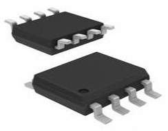 FDS6910 MOSFET: Features, Pinout, and Datasheet
27 April 20221940
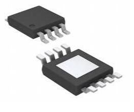
 AD8479 Precision Difference Amplifier: Pinout and Basic Connections
12 November 20211651
 STM8S005K6T6C Microcontroller: Features, Applications and Datasheet
27 December 20231937
 MC68HC705C8ACFNE: Trusted Sourcing Guide for Microcontroller Components
07 June 2025229
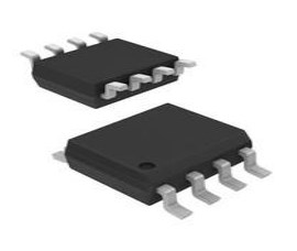
 MP1584EN 8-SOIC 100kHz~1.5MHz Voltage Regulators: Datasheet, Pinout, and Equivalents
18 April 20255989
 CD4069 Inverter CMOS: Pinout, Datasheet pdf and Circuit
04 December 202110163
 Best Practices for Yageo RC0402FR-070RL Zero Ohm Use
20 August 2025580
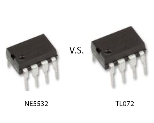 NE5532 Vs. TL072: What Is The Difference?
08 March 202224425
 How does an Inverter Work?
06 April 20219773
 What are Varactor Diodes?
24 November 20259226
 Three Phase Inverter - 180 Degree Conduction Mode
05 October 202318603
 The Era of Business Globalization: Chinese Founders Aim to Conquer the World
30 May 20227169
 Silicon Carbide: The Future of Power Electronics
06 March 20233647
 Protect USB Ports From Nefarious USB Killers
15 November 20191589
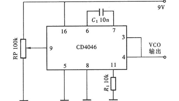 What is a Voltage Controlled Oscillator?
09 January 20268566
 An Overview of Crystal Oscillator
21 September 202013282
Microchip Technology
In Stock: 780
United States
China
Canada
Japan
Russia
Germany
United Kingdom
Singapore
Italy
Hong Kong(China)
Taiwan(China)
France
Korea
Mexico
Netherlands
Malaysia
Austria
Spain
Switzerland
Poland
Thailand
Vietnam
India
United Arab Emirates
Afghanistan
Åland Islands
Albania
Algeria
American Samoa
Andorra
Angola
Anguilla
Antigua & Barbuda
Argentina
Armenia
Aruba
Australia
Azerbaijan
Bahamas
Bahrain
Bangladesh
Barbados
Belarus
Belgium
Belize
Benin
Bermuda
Bhutan
Bolivia
Bonaire, Sint Eustatius and Saba
Bosnia & Herzegovina
Botswana
Brazil
British Indian Ocean Territory
British Virgin Islands
Brunei
Bulgaria
Burkina Faso
Burundi
Cabo Verde
Cambodia
Cameroon
Cayman Islands
Central African Republic
Chad
Chile
Christmas Island
Cocos (Keeling) Islands
Colombia
Comoros
Congo
Congo (DRC)
Cook Islands
Costa Rica
Côte d’Ivoire
Croatia
Cuba
Curaçao
Cyprus
Czechia
Denmark
Djibouti
Dominica
Dominican Republic
Ecuador
Egypt
El Salvador
Equatorial Guinea
Eritrea
Estonia
Eswatini
Ethiopia
Falkland Islands
Faroe Islands
Fiji
Finland
French Guiana
French Polynesia
Gabon
Gambia
Georgia
Ghana
Gibraltar
Greece
Greenland
Grenada
Guadeloupe
Guam
Guatemala
Guernsey
Guinea
Guinea-Bissau
Guyana
Haiti
Honduras
Hungary
Iceland
Indonesia
Iran
Iraq
Ireland
Isle of Man
Israel
Jamaica
Jersey
Jordan
Kazakhstan
Kenya
Kiribati
Kosovo
Kuwait
Kyrgyzstan
Laos
Latvia
Lebanon
Lesotho
Liberia
Libya
Liechtenstein
Lithuania
Luxembourg
Macao(China)
Madagascar
Malawi
Maldives
Mali
Malta
Marshall Islands
Martinique
Mauritania
Mauritius
Mayotte
Micronesia
Moldova
Monaco
Mongolia
Montenegro
Montserrat
Morocco
Mozambique
Myanmar
Namibia
Nauru
Nepal
New Caledonia
New Zealand
Nicaragua
Niger
Nigeria
Niue
Norfolk Island
North Korea
North Macedonia
Northern Mariana Islands
Norway
Oman
Pakistan
Palau
Palestinian Authority
Panama
Papua New Guinea
Paraguay
Peru
Philippines
Pitcairn Islands
Portugal
Puerto Rico
Qatar
Réunion
Romania
Rwanda
Samoa
San Marino
São Tomé & Príncipe
Saudi Arabia
Senegal
Serbia
Seychelles
Sierra Leone
Sint Maarten
Slovakia
Slovenia
Solomon Islands
Somalia
South Africa
South Sudan
Sri Lanka
St Helena, Ascension, Tristan da Cunha
St. Barthélemy
St. Kitts & Nevis
St. Lucia
St. Martin
St. Pierre & Miquelon
St. Vincent & Grenadines
Sudan
Suriname
Svalbard & Jan Mayen
Sweden
Syria
Tajikistan
Tanzania
Timor-Leste
Togo
Tokelau
Tonga
Trinidad & Tobago
Tunisia
Turkey
Turkmenistan
Turks & Caicos Islands
Tuvalu
U.S. Outlying Islands
U.S. Virgin Islands
Uganda
Ukraine
Uruguay
Uzbekistan
Vanuatu
Vatican City
Venezuela
Wallis & Futuna
Yemen
Zambia
Zimbabwe
![ATMEGA8515L-8AU]() ATMEGA8515L-8AU
ATMEGA8515L-8AUMicrochip Technology
![DSPIC30F6014A-30I/PF]() DSPIC30F6014A-30I/PF
DSPIC30F6014A-30I/PFMicrochip Technology
![ATMEGA32A-AU]() ATMEGA32A-AU
ATMEGA32A-AUMicrochip Technology
![ATXMEGA128A1U-AU]() ATXMEGA128A1U-AU
ATXMEGA128A1U-AUMicrochip Technology
![PIC18F46K20-I/PT]() PIC18F46K20-I/PT
PIC18F46K20-I/PTMicrochip Technology
![PIC18F6722-I/PT]() PIC18F6722-I/PT
PIC18F6722-I/PTMicrochip Technology
![PIC16F883-I/SS]() PIC16F883-I/SS
PIC16F883-I/SSMicrochip Technology
![PIC16F877-20I/PT]() PIC16F877-20I/PT
PIC16F877-20I/PTMicrochip Technology
![ATMEGA8535L-8AU]() ATMEGA8535L-8AU
ATMEGA8535L-8AUMicrochip Technology
![PIC18F4685-I/PT]() PIC18F4685-I/PT
PIC18F4685-I/PTMicrochip Technology


