
 Product
 Brand
Brand Articles
 Tools
Tools
Eliminating Rectifier Heat: LT4320 / LT4320-1 9V-72V Ideal Diode Bridge Controller Deep Dive


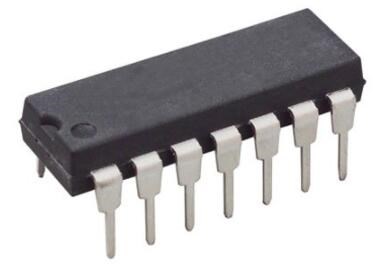
2.54mm PMIC LT4320 8-DIP (0.300, 7.62mm)
Optimize efficiency with the LT4320 / LT4320-1 Ideal Diode Bridge Controller. Replaces lossy diodes with MOSFETs for 9V-72V apps. Improve your BOM and thermal design today.
- Executive Summary: What is the LT4320 / LT4320-1?
- 1. Technical Specifications & Performance Analysis
- 2. Pinout, Package, and Configuration
- 3. Design & Integration Guide (For Engineers & Makers)
- 4. Typical Applications & Use Cases
- 5. Alternatives and Cross-Reference Guide
- 6. Frequently Asked Questions (FAQ)
- 7. Resources
- Specifications
- Datasheet PDF
Executive Summary: What is the LT4320 / LT4320-1?
The LT4320 / LT4320-1 is an ideal diode bridge controller designed to drive four external N-channel MOSFETs, replacing a traditional full-wave diode bridge rectifier to significantly reduce power dissipation and voltage drop. By eliminating the standard 0.7V to 1.2V drop of silicon or Schottky diodes, it enables smaller power supply designs and higher efficiency.
Market Position: High-performance thermal management and power efficiency solution for industrial and networking sectors.
Top Features: Wide 9V to 72V operating range, support for up to 600Hz (LT4320-1), and an integrated charge pump for all N-channel designs.
Primary Audience: Ideal for PoE hardware designers, industrial power engineers, and high-fidelity audio manufacturers.
Supply Status: Active (Widely available through authorized distributors).
1. Technical Specifications & Performance Analysis
1.1 Core Architecture (Ideal Diode Control)
The LT4320 functions by sensing the voltage across the external MOSFETs and turning them on or off to emulate the behavior of a diode, but with the ultra-low resistance ($R_{DS(ON)}$) of a transistor. Unlike passive bridges, it includes an internal charge pump that generates the necessary gate-drive voltage to allow the use of cost-effective N-channel MOSFETs for both the high-side and low-side of the bridge.
1.2 Key Electrical Characteristics
Operating Voltage: 9V to 72V, making it suitable for 12V, 24V, and 48V nominal systems.
Quiescent Current: Typically 1.5mA, ensuring minimal overhead in battery-backed or energy-sensitive systems.
Voltage Drop: Effectively reduced to $I_{load} \times R_{DS(ON)}$, often resulting in millivolt-level drops compared to the nearly 1V drop of standard bridges.
Frequency Support: The LT4320 supports DC to 60Hz (standard AC mains), while the LT4320-1 variant supports up to 600Hz for specialized power distribution.
1.3 Interfaces and Connectivity
While the LT4320 is an analog controller, its "interface" consists of high-speed gate drivers capable of switching large MOSFETs. It is designed for "set and forget" hardware implementation without the need for SPI/I2C configuration.

2. Pinout, Package, and Configuration
2.1 Pin Configuration Guide
The device is streamlined for ease of layout, typically grouping input and output pins to minimize high-current loop areas.
IN1 / IN2: AC or DC input pins.
OUTP / OUTN: Positive and Negative rectified DC outputs.
TG1 / TG2: Top-side N-channel MOSFET gate drives.
BG1 / BG2: Bottom-side N-channel MOSFET gate drives.
2.2 Naming Convention & Ordering Codes
LT4320: Optimized for DC to 60Hz (Standard AC line rectification).
LT4320-1: Optimized for DC to 600Hz (Higher frequency AC or faster transient response).
Suffixes (I/H): "I" denotes industrial temperature range (-40°C to 85°C); "H" denotes high temperature (-40°C to 125°C).
2.3 Available Packages
| Package Type | Dimensions | Common Use Case |
|---|---|---|
| 8-Lead DFN | 3mm x 3mm | Space-constrained IoT & PoE devices. |
| 12-Lead MSOP | 4.9mm x 3mm | General industrial with enhanced spacing. |
| 8-Lead PDIP | 9.27mm x 6.35mm | Prototyping and through-hole legacy boards. |
3. Design & Integration Guide (For Engineers & Makers)
3.1 Hardware Implementation
Bypass Capacitors: Place a 1µF (minimum) ceramic capacitor across OUTP and OUTN close to the IC to stabilize the internal charge pump.
PCB Layout: Use thick copper pours for the traces connecting the MOSFET drains and sources, as these will carry the full load current.
Thermal Management: While the IC stays cool, the external MOSFETs still generate some heat based on $I^2R$ losses. However, most designs can eliminate bulky heatsinks entirely.
3.2 Common Design Challenges
Issue: High-Frequency Rectification: The LT4320 is not a high-speed synchronous rectifier for 100kHz SMPS.
Fix: Use it only for input polarity protection or 50/60/400Hz mains rectification.
Issue: Voltage Spikes: AC lines often have transients exceeding 72V.
Fix: Always install a TVS (Transient Voltage Suppressor) diode across the output (OUTP to OUTN) to clamp spikes.
4. Typical Applications & Use Cases
4.1 Real-World Example: PoE Powered Devices
In Power over Ethernet (PoE) applications, the input voltage can come from either polarity on the Ethernet pairs. Using an LT4320 instead of a diode bridge allows the device to run much cooler, which is critical in the small, sealed enclosures typical of IP Security Cameras.
5. Alternatives and Cross-Reference Guide
Direct Replacements: There are few pin-compatible "ideal bridge" controllers, but the Onsemi FDMQ8205A (GreenBridge) offers an integrated MOSFET approach for lower current levels.
Discrete Alternatives: Using four TI LM74670-Q1 "Smart Diode" controllers can achieve a similar result but requires four separate ICs, significantly increasing complexity.
Cost-Effective Options: Standard Schottky Bridge Rectifiers (e.g., GBU8J) are significantly cheaper but require large heatsinks and waste 2W-10W of power in high-current designs.
6. Frequently Asked Questions (FAQ)
Q: What is the difference between LT4320 and LT4320-1? A: The LT4320 is for standard 50/60Hz AC, while the LT4320-1 supports up to 600Hz, making it suitable for 400Hz airborne power systems.
Q: Can LT4320 be used in automotive 12V systems? A: Yes, it is excellent for reverse polarity protection, but ensure you have adequate TVS protection against "load dump" transients.
Q: Does it require a separate power supply? A: No, it is self-powered from the input voltage (9V-72V).
Q: Can I use any N-channel MOSFET? A: You should select MOSFETs with a gate threshold voltage ($V_{GS(th)}$) compatible with the LT4320’s gate drive (typically ~7V-10V above the rail).
7. Resources
Datasheet: Available via Analog Devices website.
Simulation: Supported in LTspice for thermal and efficiency modeling.
Evaluation Boards: DC1823A (for DFN) or DC1823B (for MSOP).
Specifications
Datasheet PDF
- Datasheets :
- Design Resources :
- Simulation Models :
 BC177 Low Power PNP Transistor: Datasheet pdf, Pinout and Equivalents
02 December 20212920
 CD4071 Dual Input OR Gate IC: Datasheet, Pinout and Equivalents
23 October 20216716
 74LS73 Dual JK Flip-Flop IC: Datasheet, Pinout and How Do Flip Flops Work
07 December 202126885
 STM32L021K4T6 Ultra-Low-Power 32-bit MCU: Datasheet Analysis
29 February 2024204
 OV7670 vs OV2640 Which one is better?
03 March 20225692
![282080-1 Rectangular Connectors Housings CONN PLUG BLACK[Video]: Datasheet, Features, and Drawings](https://res.utmel.com/Images/Article/61199823-de3e-4a6f-a253-0628aba362d6.jpg) 282080-1 Rectangular Connectors Housings CONN PLUG BLACK[Video]: Datasheet, Features, and Drawings
282080-1 Rectangular Connectors Housings CONN PLUG BLACK[Video]: Datasheet, Features, and Drawings29 March 20223232
 STM32G0 Microcontroller: Pinout, Diagram and Datasheet
29 September 202111027
 1N4004 Rectifier Diode: Pinout, Equivalent and Datasheet
09 July 20218838
 What is Gallium nitride (GaN) and where can we use it?
23 April 20225096
 Electronic components distributor UTMEL Stands Out at electronica china 2024
09 July 20244867
 Semiconductor Equipment Industry Research
25 March 20245001
 Structure and Working Principle of Field Effect Transistors
07 April 202540506
 Sourcing GaN Power Devices for AI Servers, EVs, and Industrial Applications
10 July 2026142
 Diode Basis: Symbol, Types and Applications
09 January 202615003
 cr2450 vs cr2032 what to know before replacing
20 August 20253853
 Introduction to DDIC (Display Driver IC)
07 January 202634050
Linear Technology/Analog Devices
In Stock
United States
China
Canada
Japan
Russia
Germany
United Kingdom
Singapore
Italy
Hong Kong(China)
Taiwan(China)
France
Korea
Mexico
Netherlands
Malaysia
Austria
Spain
Switzerland
Poland
Thailand
Vietnam
India
United Arab Emirates
Afghanistan
Åland Islands
Albania
Algeria
American Samoa
Andorra
Angola
Anguilla
Antigua & Barbuda
Argentina
Armenia
Aruba
Australia
Azerbaijan
Bahamas
Bahrain
Bangladesh
Barbados
Belarus
Belgium
Belize
Benin
Bermuda
Bhutan
Bolivia
Bonaire, Sint Eustatius and Saba
Bosnia & Herzegovina
Botswana
Brazil
British Indian Ocean Territory
British Virgin Islands
Brunei
Bulgaria
Burkina Faso
Burundi
Cabo Verde
Cambodia
Cameroon
Cayman Islands
Central African Republic
Chad
Chile
Christmas Island
Cocos (Keeling) Islands
Colombia
Comoros
Congo
Congo (DRC)
Cook Islands
Costa Rica
Côte d’Ivoire
Croatia
Cuba
Curaçao
Cyprus
Czechia
Denmark
Djibouti
Dominica
Dominican Republic
Ecuador
Egypt
El Salvador
Equatorial Guinea
Eritrea
Estonia
Eswatini
Ethiopia
Falkland Islands
Faroe Islands
Fiji
Finland
French Guiana
French Polynesia
Gabon
Gambia
Georgia
Ghana
Gibraltar
Greece
Greenland
Grenada
Guadeloupe
Guam
Guatemala
Guernsey
Guinea
Guinea-Bissau
Guyana
Haiti
Honduras
Hungary
Iceland
Indonesia
Iran
Iraq
Ireland
Isle of Man
Israel
Jamaica
Jersey
Jordan
Kazakhstan
Kenya
Kiribati
Kosovo
Kuwait
Kyrgyzstan
Laos
Latvia
Lebanon
Lesotho
Liberia
Libya
Liechtenstein
Lithuania
Luxembourg
Macao(China)
Madagascar
Malawi
Maldives
Mali
Malta
Marshall Islands
Martinique
Mauritania
Mauritius
Mayotte
Micronesia
Moldova
Monaco
Mongolia
Montenegro
Montserrat
Morocco
Mozambique
Myanmar
Namibia
Nauru
Nepal
New Caledonia
New Zealand
Nicaragua
Niger
Nigeria
Niue
Norfolk Island
North Korea
North Macedonia
Northern Mariana Islands
Norway
Oman
Pakistan
Palau
Palestinian Authority
Panama
Papua New Guinea
Paraguay
Peru
Philippines
Pitcairn Islands
Portugal
Puerto Rico
Qatar
Réunion
Romania
Rwanda
Samoa
San Marino
São Tomé & Príncipe
Saudi Arabia
Senegal
Serbia
Seychelles
Sierra Leone
Sint Maarten
Slovakia
Slovenia
Solomon Islands
Somalia
South Africa
South Sudan
Sri Lanka
St Helena, Ascension, Tristan da Cunha
St. Barthélemy
St. Kitts & Nevis
St. Lucia
St. Martin
St. Pierre & Miquelon
St. Vincent & Grenadines
Sudan
Suriname
Svalbard & Jan Mayen
Sweden
Syria
Tajikistan
Tanzania
Timor-Leste
Togo
Tokelau
Tonga
Trinidad & Tobago
Tunisia
Turkey
Turkmenistan
Turks & Caicos Islands
Tuvalu
U.S. Outlying Islands
U.S. Virgin Islands
Uganda
Ukraine
Uruguay
Uzbekistan
Vanuatu
Vatican City
Venezuela
Wallis & Futuna
Yemen
Zambia
Zimbabwe
![LTC4415EMSE#PBF]() LTC4415EMSE#PBF
LTC4415EMSE#PBFLinear Technology/Analog Devices
![LTC4359IMS8#TRPBF]() LTC4359IMS8#TRPBF
LTC4359IMS8#TRPBFLinear Technology/Analog Devices
![LT4351IMS#PBF]() LT4351IMS#PBF
LT4351IMS#PBFLinear Technology/Analog Devices
![LTC4412HVIS6#TRMPBF]() LTC4412HVIS6#TRMPBF
LTC4412HVIS6#TRMPBFLinear Technology/Analog Devices
![LTC4413EDD#TRPBF]() LTC4413EDD#TRPBF
LTC4413EDD#TRPBFLinear Technology/Analog Devices
![LT4321HUF#TRPBF]() LT4321HUF#TRPBF
LT4321HUF#TRPBFLinear Technology/Analog Devices
![LT4321IUF#TRPBF]() LT4321IUF#TRPBF
LT4321IUF#TRPBFLinear Technology/Analog Devices
![LTC4357CMS8#TRPBF]() LTC4357CMS8#TRPBF
LTC4357CMS8#TRPBFLinear Technology/Analog Devices
![LTC4359HMS8#PBF]() LTC4359HMS8#PBF
LTC4359HMS8#PBFLinear Technology/Analog Devices
![LTC4412HVIS6#TRPBF]() LTC4412HVIS6#TRPBF
LTC4412HVIS6#TRPBFLinear Technology/Analog Devices


