
AD8302 2.7 GHz RF Gain and Phase Detector: Datasheet, Pinout, and Performance Review


IC RF DETECT 2.7GHZ 14TSSOP
The AD8302 by Analog Devices measures gain and phase difference up to 2.7 GHz. Ideal for VSWR and PA linearization. Buy AD8302 or download the datasheet now.
- Executive Summary: What is the AD8302?
- 1. Technical Specifications & Performance Analysis
- 2. Pinout, Package, and Configuration
- 3. Design & Integration Guide (For Engineers & Makers)
- 4. Typical Applications & Use Cases
- 5. Alternatives and Cross-Reference Guide
- 6. Frequently Asked Questions (FAQ)
- 7. Resources
- Specifications
- Parts with Similar Specs
- Datasheet PDF
Executive Summary: What is the AD8302?
The AD8302 is a fully integrated RF integrated circuit designed to measure the amplitude ratio (gain/loss) and phase difference between two independent input signals from low frequencies up to 2.7 GHz. It provides two precise linear-scale outputs: one representing the relative gain between inputs and the other representing the phase difference.
Market Position: High-performance, industry-standard RF detector for signal analysis and linearization.
Top Features: 60 dB dynamic range (-60 dBm to 0 dBm), 0° to 180° phase measurement, and a stable 1.8V internal reference.
Primary Audience: Ideal for RF design engineers, telecommunications infrastructure developers, and advanced hobbyists working on SDR (Software Defined Radio) or antenna analysis.
Supply Status: Active; widely available through major distributors.

1. Technical Specifications & Performance Analysis
The AD8302 is a "system-on-a-chip" for RF signal comparison, eliminating the need for complex discrete circuits involving multiple mixers and log amps.
1.1 Core Architecture: Dual Demodulating Log Amps
The AD8302 utilizes a pair of matched demodulating logarithmic amplifiers. By calculating the difference between the outputs of these two log amps, the chip produces a voltage proportional to the ratio of the input signals (the gain). Simultaneously, an internal multiplier-style phase detector compares the signals to output a voltage proportional to their phase difference.
1.2 Key Electrical Characteristics
Frequency Range: Operates from Low Frequency (LF) up to 2.7 GHz, covering most cellular and ISM bands.
Supply Voltage: Flexible operation between 2.7V and 5.5V, making it compatible with both 3.3V and 5V logic systems.
Gain Scaling: Highly precise 30 mV/dB output slope.
Phase Scaling: Provides 10 mV/Degree sensitivity.
Current Consumption: Typically draws 20 mA, suitable for most base station and portable test equipment power budgets.
1.3 Interfaces and Connectivity
The AD8302 is purely analog in its output, providing two measurement voltages: VMAG (Magnitude/Gain) and VPHS (Phase). This allows for direct interfacing with ADC (Analog-to-Digital Converter) inputs on microcontrollers like the STM32 or Arduino for real-time digital monitoring.

2. Pinout, Package, and Configuration
The AD8302 is designed for high-frequency stability, which is reflected in its pin layout.
2.1 Pin Configuration Guide

INPA / INPB (Pins 1, 14): The two RF input channels.
VMAG (Pin 7): The gain/loss output voltage.
VPHS (Pin 8): The phase difference output voltage.
VREF (Pin 12): Provides a stable 1.8V reference for biasing or ADC calibration.
MFLT / PFLT (Pins 6, 9): Filter capacitor connections to set the measurement bandwidth.
2.2 Naming Convention & Ordering Codes
The most common ordering code is AD8302ARUZ.
- AD8302: The base part number.
- ARU: Indicates the TSSOP package style.
- Z: Denotes RoHS compliance (Lead-Free).
2.3 Available Packages
| Package Type | Dimensions | Common Use Case |
|---|---|---|
| 14-Lead TSSOP | 4.4mm x 5.0mm | Standard PCB assembly; compact for multi-channel systems. |
Note: The TSSOP package is manageable for skilled hand-soldering but is primarily intended for SMT machine assembly.
3. Design & Integration Guide (For Engineers & Makers)
Pro Tip: For optimal RF performance, use a four-layer PCB with a dedicated ground plane directly beneath the AD8302.
3.1 Hardware Implementation
Bypass Capacitors: Place 100 pF and 0.1 µF capacitors as close to the VPOS pin as possible to minimize power supply noise.
Input Matching: The AD8302 has a high input impedance (~3 kΩ). In standard 50Ω systems, you must add a 52.3Ω shunt resistor to ground at both INPA and INPB to ensure proper power transfer and low VSWR.
Thermal Management: The device dissipates roughly 100 mW; no external heatsink is required under normal operating temperatures.
3.2 Common Design Challenges
Issue: Phase Ambiguity: The AD8302 outputs 0V to 1.8V for a 0° to 180° shift. It cannot distinguish between +90° and -90°.
Fix: If 360° coverage is needed, use a 90° phase shifter on one input or consider an I/Q demodulator like the ADL5380.
Issue: Low Frequency Ripple: At frequencies below 10 MHz, the output may show significant ripple.
Fix: Increase the capacitor values on the MFLT and PFLT pins to narrow the video bandwidth and smooth the output.
4. Typical Applications & Use Cases
🎬 Watch Tutorial: AD8302
4.1 Real-World Example: VSWR Measurement
The AD8302 is the "gold standard" for measuring Return Loss (VSWR) in transmitter signal chains. By connecting one input to the forward path and the other to the reflected path via a directional coupler, the AD8302 provides a real-time voltage representing the antenna match quality.
5. Alternatives and Cross-Reference Guide
Direct Replacements: There are no pin-to-pin identical competitors, but the ADL5920 is a modern alternative that integrates a directional bridge for easier VSWR measurements.
Better Performance (360° Phase): The ADL5380 or TRF3711 are better suited for full vector signal analysis.
Cost-Effective Options: For simple power measurement without phase, the AD8307 or LT5534 are smaller and cheaper alternatives.
6. Frequently Asked Questions (FAQ)
Q: What is the difference between AD8302 and AD8318?
A: The AD8302 measures the ratio and phase between two signals. The AD8318 is a single-channel logarithmic detector meant for absolute power measurement.
Q: Can AD8302 be used in 5GHz WiFi applications?
A: No, the AD8302 is rated up to 2.7 GHz. For 5 GHz, look at the ADL5513 or similar high-frequency detectors.
Q: Where can I find the datasheet and library files for AD8302?
A: The official datasheet is available on the Analog Devices website. CAD symbols are widely available on SnapEDA and Ultra Librarian.
Q: Is AD8302 suitable for battery-operated devices?
A: Yes, with a 20 mA current draw and a minimum supply of 2.7V, it is very efficient for portable RF test gear.
7. Resources
Development Tools: AD8302-EVALZ Evaluation Board.
Software Support: ADI DiffAmpCalc™ for signal conditioning simulation.
Related Parts: ADL5902 (TruPwr™ Detector).
Specifications
Parts with Similar Specs
- ImagePart NumberManufacturerPackage / CaseNumber of PinsMountFrequencySupply VoltageRadiation HardeningNumber of TerminationsPackagingView Compare
![AD8302ARU-REEL7]()
AD8302ARU-REEL7
14-TSSOP (0.173, 4.40mm Width)
14
Surface Mount
2.7GHz
5 V
-
14
Tape & Reel (TR)
![AD8345AREZ-RL7]()
14-TSSOP (0.173, 4.40mm Width)
14
Surface Mount
0Hz ~ 2.5GHz
-
No
14
Tube
![PIC12F529T39AT-I/ST]()
16-TSSOP (0.173, 4.40mm Width) Exposed Pad
16
Surface Mount
-
-
No
-
Tape & Reel (TR)
![AD8343ARUZ]()
14-TSSOP (0.173, 4.40mm Width)
14
Surface Mount
310MHz, 433MHz, 868MHz, 915MHz
3 V
No
14
Tape & Reel (TR)
![MCP2030T-I/ST]()
14-TSSOP (0.173, 4.40mm Width)
14
Surface Mount
125kHz
-
No
14
Tape & Reel (TR)


Datasheet PDF
- Datasheets :
- ConflictMineralStatement :
 TLV61046ADBVT DC-DC Switching Boost Converter, 1 MHz, 3.3V-28V, and SOT-23-6
14 February 20222988
 DS3231M RTC: Pinout, Application, Circuit
16 August 20213794
 MOC3021M Optocoupler: Circuit, Pinout, and Datasheet
02 March 20226976
 ATMEGA2560-16AU Microcontroller: Features, Pinout, and Datasheet
24 February 202211046
![LMR300 Coaxial Cable 50 Ohms BLACK PE[Video]](https://res.utmel.com/Images/Article/25e1b1ff-d93a-4599-a7ed-6c27f45cfe7f.png) LMR300 Coaxial Cable 50 Ohms BLACK PE[Video]
LMR300 Coaxial Cable 50 Ohms BLACK PE[Video]12 June 2024394
 LM239PT Comparator: Feature, Specification, and Datasheet
29 June 2021729
 SN7406N Inverting Buffer IC: How to use the SN7406N?
16 May 20223563
 TL494 PWM Controller: Technical Guide, Datasheet Analysis, and Circuit Design
17 January 2026608
 What is a Transmitter?
12 October 20215329
 How does a Photodiode Work?
15 August 202021566
 Google Acquires MicroLED Display Company Raxium, May Boost Its AR Headset
09 May 20221835
 Graphics Card Explained: Classification, Working and Structure
27 May 202113047
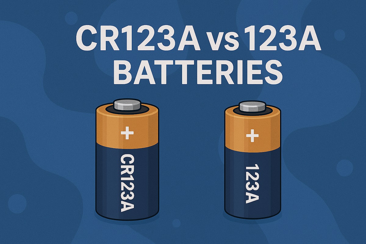 CR123A vs 123A Batteries Explained for 2025
27 May 20252554
 Facial Recognition: Features, Working and Applications
02 September 20218969
 Introduction to Types of Diodes
20 October 202515821
 Apple M1 Ultra -- The Technology Behind the Chip Interconnection
12 March 20226304
Analog Devices Inc.
In Stock: 210
United States
China
Canada
Japan
Russia
Germany
United Kingdom
Singapore
Italy
Hong Kong(China)
Taiwan(China)
France
Korea
Mexico
Netherlands
Malaysia
Austria
Spain
Switzerland
Poland
Thailand
Vietnam
India
United Arab Emirates
Afghanistan
Åland Islands
Albania
Algeria
American Samoa
Andorra
Angola
Anguilla
Antigua & Barbuda
Argentina
Armenia
Aruba
Australia
Azerbaijan
Bahamas
Bahrain
Bangladesh
Barbados
Belarus
Belgium
Belize
Benin
Bermuda
Bhutan
Bolivia
Bonaire, Sint Eustatius and Saba
Bosnia & Herzegovina
Botswana
Brazil
British Indian Ocean Territory
British Virgin Islands
Brunei
Bulgaria
Burkina Faso
Burundi
Cabo Verde
Cambodia
Cameroon
Cayman Islands
Central African Republic
Chad
Chile
Christmas Island
Cocos (Keeling) Islands
Colombia
Comoros
Congo
Congo (DRC)
Cook Islands
Costa Rica
Côte d’Ivoire
Croatia
Cuba
Curaçao
Cyprus
Czechia
Denmark
Djibouti
Dominica
Dominican Republic
Ecuador
Egypt
El Salvador
Equatorial Guinea
Eritrea
Estonia
Eswatini
Ethiopia
Falkland Islands
Faroe Islands
Fiji
Finland
French Guiana
French Polynesia
Gabon
Gambia
Georgia
Ghana
Gibraltar
Greece
Greenland
Grenada
Guadeloupe
Guam
Guatemala
Guernsey
Guinea
Guinea-Bissau
Guyana
Haiti
Honduras
Hungary
Iceland
Indonesia
Iran
Iraq
Ireland
Isle of Man
Israel
Jamaica
Jersey
Jordan
Kazakhstan
Kenya
Kiribati
Kosovo
Kuwait
Kyrgyzstan
Laos
Latvia
Lebanon
Lesotho
Liberia
Libya
Liechtenstein
Lithuania
Luxembourg
Macao(China)
Madagascar
Malawi
Maldives
Mali
Malta
Marshall Islands
Martinique
Mauritania
Mauritius
Mayotte
Micronesia
Moldova
Monaco
Mongolia
Montenegro
Montserrat
Morocco
Mozambique
Myanmar
Namibia
Nauru
Nepal
New Caledonia
New Zealand
Nicaragua
Niger
Nigeria
Niue
Norfolk Island
North Korea
North Macedonia
Northern Mariana Islands
Norway
Oman
Pakistan
Palau
Palestinian Authority
Panama
Papua New Guinea
Paraguay
Peru
Philippines
Pitcairn Islands
Portugal
Puerto Rico
Qatar
Réunion
Romania
Rwanda
Samoa
San Marino
São Tomé & Príncipe
Saudi Arabia
Senegal
Serbia
Seychelles
Sierra Leone
Sint Maarten
Slovakia
Slovenia
Solomon Islands
Somalia
South Africa
South Sudan
Sri Lanka
St Helena, Ascension, Tristan da Cunha
St. Barthélemy
St. Kitts & Nevis
St. Lucia
St. Martin
St. Pierre & Miquelon
St. Vincent & Grenadines
Sudan
Suriname
Svalbard & Jan Mayen
Sweden
Syria
Tajikistan
Tanzania
Timor-Leste
Togo
Tokelau
Tonga
Trinidad & Tobago
Tunisia
Turkey
Turkmenistan
Turks & Caicos Islands
Tuvalu
U.S. Outlying Islands
U.S. Virgin Islands
Uganda
Ukraine
Uruguay
Uzbekistan
Vanuatu
Vatican City
Venezuela
Wallis & Futuna
Yemen
Zambia
Zimbabwe
![AD8361ARMZ]() AD8361ARMZ
AD8361ARMZAnalog Devices Inc.
![AD8313ARMZ]() AD8313ARMZ
AD8313ARMZAnalog Devices Inc.
![AD8319ACPZ-R7]() AD8319ACPZ-R7
AD8319ACPZ-R7Analog Devices Inc.
![AD8361ARMZ-REEL7]() AD8361ARMZ-REEL7
AD8361ARMZ-REEL7Analog Devices Inc.
![ADL5902ACPZ-R7]() ADL5902ACPZ-R7
ADL5902ACPZ-R7Analog Devices Inc.
![AD8362ARUZ-REEL7]() AD8362ARUZ-REEL7
AD8362ARUZ-REEL7Analog Devices Inc.
![ADL5513ACPZ-R7]() ADL5513ACPZ-R7
ADL5513ACPZ-R7Analog Devices Inc.
![AD8302ARUZ]() AD8302ARUZ
AD8302ARUZAnalog Devices Inc.
![LTC5507ES6#TRMPBF]() LTC5507ES6#TRMPBF
LTC5507ES6#TRMPBFAnalog Devices
![AD8362ARUZ]() AD8362ARUZ
AD8362ARUZAnalog Devices Inc.


