
 Product
 Brand
Brand Articles
 Tools
Tools
LT4320 Diode Bridge Controller: Pinout, Features and Datasheet


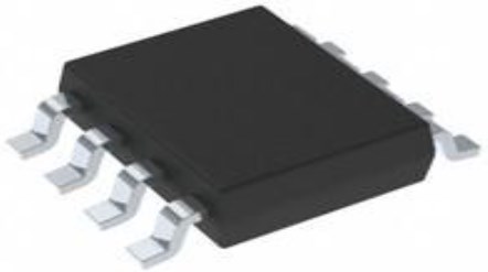
0.5mm PMIC LT4320 8-WFDFN Exposed Pad
The LT4320 is ideal diode bridge controller that drives four N-channel MOSFETs, supporting voltage rectification from DC to 600Hz typical. The LT4320 is designed for DC to 60Hz typical voltage rectification. Furthermore, Huge range of Semiconductors, Capacitors, Resistors and IcS in stock. Welcome RFQ.

[Analog Devices] LT4320-Ideal Diode Bridge vs Schottky Diode Bridge
LT4320 Pinout

Pinout
LT4320 CAD Model

symbol

footprint

3D Model
LT4320 Overview
The LT4320 is ideal diode bridge controller that drives four N-channel MOSFETs, supporting voltage rectification from DC to 600Hz typical. By maximizing available voltage and reducing power dissipation (see thermograph comparison below), the ideal diode bridge simplifies power supply design and reduces power supply cost, especially in low voltage applications. An ideal diode bridge also eliminates thermal design problems, costly heat sinks, and greatly reduces PC board area. The LT4320’s internal charge pump supports an allNMOS design, which eliminates larger and more costly PMOS switches. If the power source fails or is shorted, a fast turn-off minimizes reverse current transients. The LT4320 is designed for DC to 60Hz typical voltage rectification. Higher frequencies of operation are possible depending on MOSFET size and operating load current.
This article provides you with a basic overview of the LT4320 diode bridge controller, including its pin descriptions, features and specifications, etc., to help you quickly understand what LT4320 is.
LT4320 Features
● Maximizes Power Efficiency
● Eliminates Thermal Design Problems
● DC to 600Hz
● 9V to 72V Operating Voltage Range
● IQ = 1.5mA (Typical)
● Maximizes Available Voltage
● Available in 8-Lead (3mm × 3mm) DFN Package
Specifications
- TypeParameter
- Factory Lead Time8 Weeks
- Mounting Type
The "Mounting Type" in electronic components refers to the method used to attach or connect a component to a circuit board or other substrate, such as through-hole, surface-mount, or panel mount.
Surface Mount - Package / Case
refers to the protective housing that encases an electronic component, providing mechanical support, electrical connections, and thermal management.
8-WFDFN Exposed Pad - Surface Mount
having leads that are designed to be soldered on the side of a circuit board that the body of the component is mounted on.
YES - Operating Temperature
The operating temperature is the range of ambient temperature within which a power supply, or any other electrical equipment, operate in. This ranges from a minimum operating temperature, to a peak or maximum operating temperature, outside which, the power supply may fail.
-40°C~85°C - Packaging
Semiconductor package is a carrier / shell used to contain and cover one or more semiconductor components or integrated circuits. The material of the shell can be metal, plastic, glass or ceramic.
Tube - Published2011
- JESD-609 Code
The "JESD-609 Code" in electronic components refers to a standardized marking code that indicates the lead-free solder composition and finish of electronic components for compliance with environmental regulations.
e3 - Part Status
Parts can have many statuses as they progress through the configuration, analysis, review, and approval stages.
Active - Moisture Sensitivity Level (MSL)
Moisture Sensitivity Level (MSL) is a standardized rating that indicates the susceptibility of electronic components, particularly semiconductors, to moisture-induced damage during storage and the soldering process, defining the allowable exposure time to ambient conditions before they require special handling or baking to prevent failures
1 (Unlimited) - Number of Terminations8
- TypeBridge Rectifier
- Terminal Finish
Terminal Finish refers to the surface treatment applied to the terminals or leads of electronic components to enhance their performance and longevity. It can improve solderability, corrosion resistance, and overall reliability of the connection in electronic assemblies. Common finishes include nickel, gold, and tin, each possessing distinct properties suitable for various applications. The choice of terminal finish can significantly impact the durability and effectiveness of electronic devices.
Matte Tin (Sn) - Applications
The parameter "Applications" in electronic components refers to the specific uses or functions for which a component is designed. It encompasses various fields such as consumer electronics, industrial automation, telecommunications, automotive, and medical devices. Understanding the applications helps in selecting the right components for a particular design based on performance, reliability, and compatibility requirements. This parameter also guides manufacturers in targeting their products to relevant markets and customer needs.
General Purpose - HTS Code
HTS (Harmonized Tariff Schedule) codes are product classification codes between 8-1 digits. The first six digits are an HS code, and the countries of import assign the subsequent digits to provide additional classification. U.S. HTS codes are 1 digits and are administered by the U.S. International Trade Commission.
8542.39.00.01 - Voltage - Supply
Voltage - Supply refers to the range of voltage levels that an electronic component or circuit is designed to operate with. It indicates the minimum and maximum supply voltage that can be applied for the device to function properly. Providing supply voltages outside this range can lead to malfunction, damage, or reduced performance. This parameter is critical for ensuring compatibility between different components in a circuit.
9V~72V - Terminal Position
In electronic components, the term "Terminal Position" refers to the physical location of the connection points on the component where external electrical connections can be made. These connection points, known as terminals, are typically used to attach wires, leads, or other components to the main body of the electronic component. The terminal position is important for ensuring proper connectivity and functionality of the component within a circuit. It is often specified in technical datasheets or component specifications to help designers and engineers understand how to properly integrate the component into their circuit designs.
DUAL - Peak Reflow Temperature (Cel)
Peak Reflow Temperature (Cel) is a parameter that specifies the maximum temperature at which an electronic component can be exposed during the reflow soldering process. Reflow soldering is a common method used to attach electronic components to a circuit board. The Peak Reflow Temperature is crucial because it ensures that the component is not damaged or degraded during the soldering process. Exceeding the specified Peak Reflow Temperature can lead to issues such as component failure, reduced performance, or even permanent damage to the component. It is important for manufacturers and assemblers to adhere to the recommended Peak Reflow Temperature to ensure the reliability and functionality of the electronic components.
260 - Number of Functions1
- Terminal Pitch
The center distance from one pole to the next.
0.5mm - Time@Peak Reflow Temperature-Max (s)
Time@Peak Reflow Temperature-Max (s) refers to the maximum duration that an electronic component can be exposed to the peak reflow temperature during the soldering process, which is crucial for ensuring reliable solder joint formation without damaging the component.
30 - Base Part Number
The "Base Part Number" (BPN) in electronic components serves a similar purpose to the "Base Product Number." It refers to the primary identifier for a component that captures the essential characteristics shared by a group of similar components. The BPN provides a fundamental way to reference a family or series of components without specifying all the variations and specific details.
LT4320 - Pin Count
a count of all of the component leads (or pins)
8 - JESD-30 Code
JESD-30 Code refers to a standardized descriptive designation system established by JEDEC for semiconductor-device packages. This system provides a systematic method for generating designators that convey essential information about the package's physical characteristics, such as size and shape, which aids in component identification and selection. By using JESD-30 codes, manufacturers and engineers can ensure consistency and clarity in the specification of semiconductor packages across various applications and industries.
S-PDSO-N8 - Current - Supply
Current - Supply is a parameter in electronic components that refers to the maximum amount of electrical current that the component can provide to the circuit it is connected to. It is typically measured in units of amperes (A) and is crucial for determining the power handling capability of the component. Understanding the current supply rating is important for ensuring that the component can safely deliver the required current without overheating or failing. It is essential to consider this parameter when designing circuits to prevent damage to the component and ensure proper functionality of the overall system.
1.5mA - FET Type
"FET Type" refers to the type of Field-Effect Transistor (FET) being used in an electronic component. FETs are three-terminal semiconductor devices that can be classified into different types based on their construction and operation. The main types of FETs include Metal-Oxide-Semiconductor FETs (MOSFETs), Junction FETs (JFETs), and Insulated-Gate Bipolar Transistors (IGBTs).Each type of FET has its own unique characteristics and applications. MOSFETs are commonly used in digital circuits due to their high input impedance and low power consumption. JFETs are often used in low-noise amplifiers and switching circuits. IGBTs combine the high input impedance of MOSFETs with the high current-carrying capability of bipolar transistors, making them suitable for high-power applications like motor control and power inverters.When selecting an electronic component, understanding the FET type is crucial as it determines the device's performance and suitability for a specific application. It is important to consider factors such as voltage ratings, current handling capabilities, switching speeds, and power dissipation when choosing the right FET type for a particular circuit design.
N-Channel - Ratio - Input:Output
The parameter "Ratio - Input:Output" in electronic components refers to the relationship between the input and output quantities of a device or system. It is a measure of how the input signal or energy is transformed or converted into the output signal or energy. This ratio is often expressed as a numerical value or percentage, indicating the efficiency or effectiveness of the component in converting the input to the desired output. A higher ratio typically signifies better performance or higher efficiency, while a lower ratio may indicate losses or inefficiencies in the conversion process. Understanding and optimizing the input-output ratio is crucial in designing and evaluating electronic components for various applications.
Bridge (1) - Internal Switch(s)
The term "Internal Switch(s)" in electronic components typically refers to a built-in mechanism within a device that allows for the control of electrical current flow. These internal switches can be used to turn circuits on or off, change the direction of current, or regulate the flow of electricity within the component. They are often designed to be controlled externally, either manually or automatically, to enable various functions or operations within the electronic device. Internal switches play a crucial role in the overall functionality and performance of electronic components by providing a means to manage and manipulate electrical signals effectively.
No - Length3mm
- Height Seated (Max)
Height Seated (Max) is a parameter in electronic components that refers to the maximum allowable height of the component when it is properly seated or installed on a circuit board or within an enclosure. This specification is crucial for ensuring proper fit and alignment within the overall system design. Exceeding the maximum seated height can lead to mechanical interference, electrical shorts, or other issues that may impact the performance and reliability of the electronic device. Manufacturers provide this information to help designers and engineers select components that will fit within the designated space and function correctly in the intended application.
0.85mm - Width3mm
- RoHS Status
RoHS means “Restriction of Certain Hazardous Substances” in the “Hazardous Substances Directive” in electrical and electronic equipment.
ROHS3 Compliant
LT4320 Functional Block Diagram

Block Diagram
LT4320 Operation
Electronic systems that receive power from an AC power source or a DC polarity-agnostic power source often employ a 4-diode rectifier. The traditional diode bridge comes with an efficiency loss due to the voltage drop generated across two conducting diodes. The voltage drop reduces the available supply voltage and dissipates significant power especially in low voltage applications. By maximizing available voltage and reducing power dissipation, the ideal diode bridge simplifies power supply design and reduces power supply cost. An ideal diode bridge also eliminates thermal design problems, costly heat sinks, and greatly reduces PC board area.
The LT4320 is designed for DC to 60Hz typical voltage rectification. Higher frequencies of operation are possible depending on MOSFET size and operating load current.
Parts with Similar Specs
LT4320 Application
● Security Cameras
● Terrestrial or Airborne Power Distribution Systems
● Power-over-Ethernet Powered Device with a Secondary Input
● Polarity-Agnostic Power Input
● Diode Bridge Replacement
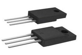
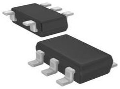
LT4320 Package
.png")
Package
LT4320 Manufacturer
As a member of the S&P 500, Linear Technology Corporation is committed to designing, manufacturing and marketing a extensive line of high performance analog integrated circuits for main companies around the world. Between the analog world and digital electronic products in communications, networks, industry, automobiles, computers, medical, instrumentation, consumer, military and aerospace systems, our products have built an important bridge for them. Our products include not only the production of power management, data conversion, signal conditioning, RF and interface ICs, μModule subsystems, but also wireless sensor network products.
Datasheet PDF
- Datasheets :
- Design Resources :
Trend Analysis
What is the essential property of the LT4320?
The LT4320 is ideal diode bridge controller that drives four N-channel MOSFETs, supporting voltage rectification from DC to 600Hz typical.
What is the difference between the LT4320 and LT4320-1 when used for typical voltage rectification?
The LT4320 is designed for DC to 60Hz typical voltage rectification, while the LT4320-1 is designed for DC to 600Hz typical voltage rectification.
What should be done for applications that may encounter transient overvoltage events higher than the LT4320 absolute maximum rating?
For applications that may encounter brief overvoltage events higher than the LT4320 absolute maximum rating, install a unidirectional transient voltage suppressor (TVS) between the OUTP and OUTN pins as close as possible to the LT4320.
 STP9NK60ZFP Power MOSFET: Pinout, Datasheet, and Features
11 September 20212580
 A Comprehensive Guide to LTZ1000ACH Voltage Reference IC
06 March 2024544
![The Comprehensive to STM32F407VET6[FAQ]](https://res.utmel.com/Images/Article/df76e74d-9337-47b3-9993-b6057bd48ec5.jpg) The Comprehensive to STM32F407VET6[FAQ]
The Comprehensive to STM32F407VET6[FAQ]30 December 20223516
 MIC2775 Micro-Power Voltage Supervisor: Pinout, Equivalent and Datasheet
12 April 20221615
 2N2907A Bipolar Transistor PNP TO-18: Datasheet, Pinout, and Equivalents
09 February 20222282
 LM53601LQDSXTQ1: Pinout, Automotive, Step-Down, Converter
14 February 2022304
 CD4051BE: Featurs, Applications, and Datasheet
08 November 20232320
 STM32G030K6T6 Microcontrollers: Features, Applications and Datasheet
20 December 20232859
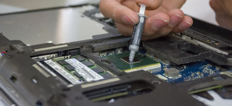 Thermal Pads vs Thermal Paste Understanding the Key Differences
19 July 20252244
 Semiconductor Industry Poised for $1 Trillion Growth Opportunity by 2030
20 November 20234105
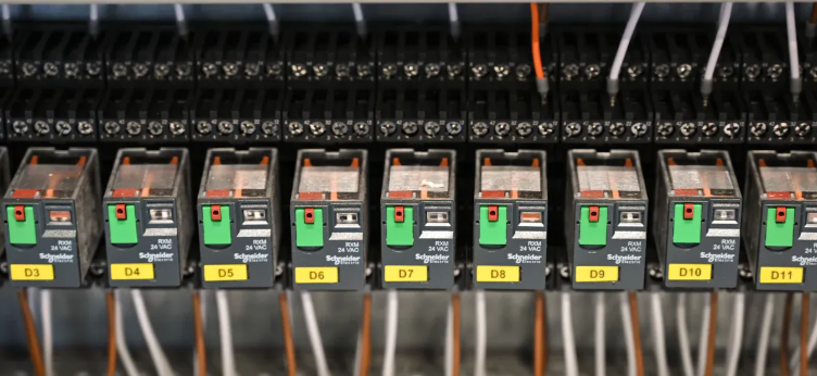 How to Select a Power Relay That Fits Your Requirements
10 July 20252728
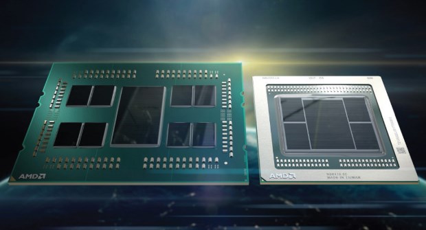 Chiplet Brings Change to the Business Model of IP Design Companies
05 September 20224234
 Modeling Wide Band-Gap Semiconductors for Enhanced Performance
31 January 20243447
 New Crisis in Semiconductors: Neon Gas Prices Soar 9 Times
21 March 20228846
 Top Chinese Photoresist Manufacturers Guide
07 January 20229138
 How do Solar Cells Work?
20 November 20203008
Linear Technology/Analog Devices
In Stock
United States
China
Canada
Japan
Russia
Germany
United Kingdom
Singapore
Italy
Hong Kong(China)
Taiwan(China)
France
Korea
Mexico
Netherlands
Malaysia
Austria
Spain
Switzerland
Poland
Thailand
Vietnam
India
United Arab Emirates
Afghanistan
Åland Islands
Albania
Algeria
American Samoa
Andorra
Angola
Anguilla
Antigua & Barbuda
Argentina
Armenia
Aruba
Australia
Azerbaijan
Bahamas
Bahrain
Bangladesh
Barbados
Belarus
Belgium
Belize
Benin
Bermuda
Bhutan
Bolivia
Bonaire, Sint Eustatius and Saba
Bosnia & Herzegovina
Botswana
Brazil
British Indian Ocean Territory
British Virgin Islands
Brunei
Bulgaria
Burkina Faso
Burundi
Cabo Verde
Cambodia
Cameroon
Cayman Islands
Central African Republic
Chad
Chile
Christmas Island
Cocos (Keeling) Islands
Colombia
Comoros
Congo
Congo (DRC)
Cook Islands
Costa Rica
Côte d’Ivoire
Croatia
Cuba
Curaçao
Cyprus
Czechia
Denmark
Djibouti
Dominica
Dominican Republic
Ecuador
Egypt
El Salvador
Equatorial Guinea
Eritrea
Estonia
Eswatini
Ethiopia
Falkland Islands
Faroe Islands
Fiji
Finland
French Guiana
French Polynesia
Gabon
Gambia
Georgia
Ghana
Gibraltar
Greece
Greenland
Grenada
Guadeloupe
Guam
Guatemala
Guernsey
Guinea
Guinea-Bissau
Guyana
Haiti
Honduras
Hungary
Iceland
Indonesia
Iran
Iraq
Ireland
Isle of Man
Israel
Jamaica
Jersey
Jordan
Kazakhstan
Kenya
Kiribati
Kosovo
Kuwait
Kyrgyzstan
Laos
Latvia
Lebanon
Lesotho
Liberia
Libya
Liechtenstein
Lithuania
Luxembourg
Macao(China)
Madagascar
Malawi
Maldives
Mali
Malta
Marshall Islands
Martinique
Mauritania
Mauritius
Mayotte
Micronesia
Moldova
Monaco
Mongolia
Montenegro
Montserrat
Morocco
Mozambique
Myanmar
Namibia
Nauru
Nepal
New Caledonia
New Zealand
Nicaragua
Niger
Nigeria
Niue
Norfolk Island
North Korea
North Macedonia
Northern Mariana Islands
Norway
Oman
Pakistan
Palau
Palestinian Authority
Panama
Papua New Guinea
Paraguay
Peru
Philippines
Pitcairn Islands
Portugal
Puerto Rico
Qatar
Réunion
Romania
Rwanda
Samoa
San Marino
São Tomé & Príncipe
Saudi Arabia
Senegal
Serbia
Seychelles
Sierra Leone
Sint Maarten
Slovakia
Slovenia
Solomon Islands
Somalia
South Africa
South Sudan
Sri Lanka
St Helena, Ascension, Tristan da Cunha
St. Barthélemy
St. Kitts & Nevis
St. Lucia
St. Martin
St. Pierre & Miquelon
St. Vincent & Grenadines
Sudan
Suriname
Svalbard & Jan Mayen
Sweden
Syria
Tajikistan
Tanzania
Timor-Leste
Togo
Tokelau
Tonga
Trinidad & Tobago
Tunisia
Turkey
Turkmenistan
Turks & Caicos Islands
Tuvalu
U.S. Outlying Islands
U.S. Virgin Islands
Uganda
Ukraine
Uruguay
Uzbekistan
Vanuatu
Vatican City
Venezuela
Wallis & Futuna
Yemen
Zambia
Zimbabwe
![LTC4415EMSE#PBF]() LTC4415EMSE#PBF
LTC4415EMSE#PBFLinear Technology/Analog Devices
![LTC4359IMS8#TRPBF]() LTC4359IMS8#TRPBF
LTC4359IMS8#TRPBFLinear Technology/Analog Devices
![LT4351IMS#PBF]() LT4351IMS#PBF
LT4351IMS#PBFLinear Technology/Analog Devices
![LTC4412HVIS6#TRMPBF]() LTC4412HVIS6#TRMPBF
LTC4412HVIS6#TRMPBFLinear Technology/Analog Devices
![LTC4413EDD#TRPBF]() LTC4413EDD#TRPBF
LTC4413EDD#TRPBFLinear Technology/Analog Devices
![LT4321HUF#TRPBF]() LT4321HUF#TRPBF
LT4321HUF#TRPBFLinear Technology/Analog Devices
![LT4321IUF#TRPBF]() LT4321IUF#TRPBF
LT4321IUF#TRPBFLinear Technology/Analog Devices
![LTC4357CMS8#TRPBF]() LTC4357CMS8#TRPBF
LTC4357CMS8#TRPBFLinear Technology/Analog Devices
![LTC4359HMS8#PBF]() LTC4359HMS8#PBF
LTC4359HMS8#PBFLinear Technology/Analog Devices
![LTC4412HVIS6#TRPBF]() LTC4412HVIS6#TRPBF
LTC4412HVIS6#TRPBFLinear Technology/Analog Devices


