
 Product
 Brand
Brand Articles
 Tools
Tools
MCP2518FD CAN FD Controller: Features, Pinout and Datasheet

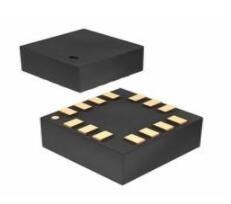
2.7V~5.5V CAN 2.0 SPI Controllers Interface ICs DUAL Controller 1.27mm 14-SOIC (0.154, 3.90mm Width)


2.7V~5.5V CAN 2.0 SPI Controllers Interface ICs DUAL Controller 1.27mm 14-SOIC (0.154, 3.90mm Width)
The MCP2518FD device is a cost-effective and small-footprint CAN FD controller that can be easily added to a microcontroller with an available SPI interface. A CAN FD channel can be easily added to a microcontroller that is either lacking a CAN FD peripheral or doesn't have enough CAN FD channels. Furthermore, Huge range of Semiconductors, Capacitors, Resistors and IcS in stock. Welcome RFQ.

CAN FD Explained - A Simple Intro (2020)
- MCP2518FD Pinout
- MCP2518FD CAD Model
- MCP2518FD Overview
- MCP2518FD Features
- Specifications
- MCP2518FD Functional Block Diagram
- MCP2518FD Equivalent
- MCP2518FD Typical Application
- MCP2518FD Package
- MCP2518FD Package Marking Information
- MCP2518FD Recommended Land Pattern
- MCP2518FD Manufacturer
- Trend Analysis
- Datasheet PDF
MCP2518FD Pinout
The following figure is the diagram of MCP2518FD pinout.

Pinout
MCP2518FD CAD Model
The followings are MCP2518FD Symbol, Footprint, and 3D Model.

PCB Symbol

PCB Footprint

3D Model
MCP2518FD Overview
The MCP2518FD device is a cost-effective and small-footprint CAN FD controller that can be easily added to a microcontroller with an available SPI interface. A CAN FD channel can be easily added to a microcontroller that is either lacking a CAN FD peripheral or doesn't have enough CAN FD channels. MCP2518FD supports both CAN frames in the Classical format (CAN2.0B) and CAN Flexible Data Rate (CAN FD) format, as specified in ISO 11898-1:2015.
This article provides you with a basic overview of the MCP2518FD CAN FD Controller, including its pin descriptions, features and specifications, etc., to help you quickly understand what MCP2518FD is.
MCP2518FD Features
◆ General
● External CAN FD Controller with Serial Peripheral Interface (SPI)
● Arbitration Bit Rate up to 1 Mbps
● Data Bit Rate up to 8 Mbps
● CAN FD Controller modes
- Mixed CAN 2.0B and CAN FD Mode
- CAN 2.0B Mode
● Conforms to ISO 11898-1:2015
◆ Message FIFOs
● 31 FIFOs, configurable as Transmit or Receive FIFOs
● One Transmit Queue (TXQ)
● Transmit Event FIFO (TEF) with 32 bit time stamp
◆ Message Transmission
● Message transmission prioritization:
- Based on priority bit field
- Message with lowest ID gets transmitted first using the Transmit Queue (TXQ)
● Programmable automatic retransmission attempts: unlimited, 3 attempts or disabled
◆ Message Reception
● 32 Flexible Filter and Mask Objects
● Each object can be configured to filter either:
- Standard ID + first 18 data bits, or
- Extended ID
● 32-bit Time Stamp
◆ Special Features
● VDD: 2.7 to 5.5V
● Active Current: maximum 20 mA at 5.5 V, 40 MHz CAN clock
● Sleep Current: 15 μA, typical
● Low Power Mode current: maximum 10 μA from –40°C to 150°C
● Message Objects are located in RAM: 2 KB
● Up to 3 Configurable Interrupt Pins
● Bus Health Diagnostics and Error Counters
● Transceiver Standby Control
● Start of frame pin for indicating the beginning of messages on the bus
● Temperature Ranges:
- Extended (E): –40°C to +125°C
- High (H): –40°C to +150°C
◆ Oscillator Options
● 40, 20 or 4 MHz Crystal or Ceramic Resonator; External Clock Input
● Clock Output with Prescaler
◆ SPI Interface
● Up to 20 MHz SPI clock speed
● Supports SPI Modes 0,0 and 1,1
● Registers and bit fields are arranged in a way to enable efficient access through SPI
◆ Safety Critical Systems
● SPI commands with CRC to detect noise on SPI interface
● Error Correction Code (ECC) protected RAM
Specifications
- TypeParameter
- Factory Lead Time7 Weeks
- Package / Case
refers to the protective housing that encases an electronic component, providing mechanical support, electrical connections, and thermal management.
14-SOIC (0.154, 3.90mm Width) - Surface Mount
having leads that are designed to be soldered on the side of a circuit board that the body of the component is mounted on.
YES - Operating Temperature
The operating temperature is the range of ambient temperature within which a power supply, or any other electrical equipment, operate in. This ranges from a minimum operating temperature, to a peak or maximum operating temperature, outside which, the power supply may fail.
-40°C~125°C - Packaging
Semiconductor package is a carrier / shell used to contain and cover one or more semiconductor components or integrated circuits. The material of the shell can be metal, plastic, glass or ceramic.
Tape & Reel (TR) - Part Status
Parts can have many statuses as they progress through the configuration, analysis, review, and approval stages.
Active - Moisture Sensitivity Level (MSL)
Moisture Sensitivity Level (MSL) is a standardized rating that indicates the susceptibility of electronic components, particularly semiconductors, to moisture-induced damage during storage and the soldering process, defining the allowable exposure time to ambient conditions before they require special handling or baking to prevent failures
3 (168 Hours) - Number of Terminations14
- Voltage - Supply
Voltage - Supply refers to the range of voltage levels that an electronic component or circuit is designed to operate with. It indicates the minimum and maximum supply voltage that can be applied for the device to function properly. Providing supply voltages outside this range can lead to malfunction, damage, or reduced performance. This parameter is critical for ensuring compatibility between different components in a circuit.
2.7V~5.5V - Terminal Position
In electronic components, the term "Terminal Position" refers to the physical location of the connection points on the component where external electrical connections can be made. These connection points, known as terminals, are typically used to attach wires, leads, or other components to the main body of the electronic component. The terminal position is important for ensuring proper connectivity and functionality of the component within a circuit. It is often specified in technical datasheets or component specifications to help designers and engineers understand how to properly integrate the component into their circuit designs.
DUAL - Terminal Form
Occurring at or forming the end of a series, succession, or the like; closing; concluding.
GULL WING - Terminal Pitch
The center distance from one pole to the next.
1.27mm - JESD-30 Code
JESD-30 Code refers to a standardized descriptive designation system established by JEDEC for semiconductor-device packages. This system provides a systematic method for generating designators that convey essential information about the package's physical characteristics, such as size and shape, which aids in component identification and selection. By using JESD-30 codes, manufacturers and engineers can ensure consistency and clarity in the specification of semiconductor packages across various applications and industries.
R-PDSO-G14 - Function
The parameter "Function" in electronic components refers to the specific role or purpose that the component serves within an electronic circuit. It defines how the component interacts with other elements, influences the flow of electrical signals, and contributes to the overall behavior of the system. Functions can include amplification, signal processing, switching, filtering, and energy storage, among others. Understanding the function of each component is essential for designing effective and efficient electronic systems.
Controller - Interface
In electronic components, the term "Interface" refers to the point at which two different systems, devices, or components connect and interact with each other. It can involve physical connections such as ports, connectors, or cables, as well as communication protocols and standards that facilitate the exchange of data or signals between the connected entities. The interface serves as a bridge that enables seamless communication and interoperability between different parts of a system or between different systems altogether. Designing a reliable and efficient interface is crucial in ensuring proper functionality and performance of electronic components and systems.
SPI - Clock Frequency
Clock frequency, also known as clock speed, refers to the rate at which a processor or electronic component can execute instructions. It is measured in hertz (Hz) and represents the number of cycles per second that the component can perform. A higher clock frequency typically indicates a faster processing speed and better performance. However, it is important to note that other factors such as architecture, efficiency, and workload also play a significant role in determining the overall performance of a component. In summary, clock frequency is a crucial parameter that influences the speed and efficiency of electronic components in processing data and executing tasks.
40MHz - Current - Supply
Current - Supply is a parameter in electronic components that refers to the maximum amount of electrical current that the component can provide to the circuit it is connected to. It is typically measured in units of amperes (A) and is crucial for determining the power handling capability of the component. Understanding the current supply rating is important for ensuring that the component can safely deliver the required current without overheating or failing. It is essential to consider this parameter when designing circuits to prevent damage to the component and ensure proper functionality of the overall system.
20mA - Protocol
In electronic components, the parameter "Protocol" refers to a set of rules and standards that govern the communication between devices. It defines the format, timing, sequencing, and error checking methods for data exchange between different components or systems. Protocols ensure that devices can understand and interpret data correctly, enabling them to communicate effectively with each other. Common examples of protocols in electronics include USB, Ethernet, SPI, I2C, and Bluetooth, each with its own specifications for data transmission. Understanding and adhering to protocols is essential for ensuring compatibility and reliable communication between electronic devices.
CAN - Boundary Scan
Boundary scan is a testing technique used in electronic components to verify the interconnections between integrated circuits on a printed circuit board. It allows for the testing of digital circuits by providing a way to shift data in and out of devices through a serial interface. This method helps in identifying faults such as short circuits, open circuits, and incorrect connections without the need for physical access to the individual components. Boundary scan is commonly used during manufacturing, testing, and debugging processes to ensure the quality and reliability of electronic products.
NO - Low Power Mode
Low Power Mode is a feature found in electronic components, such as microcontrollers, processors, and devices, that allows them to operate at reduced power consumption levels. When activated, the component typically reduces its clock speed, voltage, or disables certain functions to conserve energy. This mode is often used to extend battery life in portable devices or reduce overall power consumption in energy-efficient systems. Low Power Mode can be triggered automatically based on certain conditions, such as low battery levels, or manually by the user or software. It is a crucial feature in modern electronics to balance performance with energy efficiency.
YES - Number of Serial I/Os1
- Standards
The parameter "Standards" in electronic components refers to established criteria or specifications that ensure interoperability, safety, and performance across various electronic devices and systems. These standards are often set by recognized organizations and describe the characteristics, dimensions, and testing methods for components. Adherence to these standards helps manufacturers produce compatible and reliable products, facilitates communication between devices, and ensures compliance with regulatory requirements. Standards play a crucial role in the consistency and quality of electronic components in the industry.
CAN 2.0 - Bus Compatibility
Bus compatibility in electronic components refers to the ability of a device to communicate effectively with other devices on a shared data bus. This parameter is crucial in ensuring that different components can exchange information seamlessly and operate together without compatibility issues. It involves factors such as voltage levels, signal timing, and data protocols that need to be standardized for proper communication. Components with good bus compatibility can work together efficiently in a system, while those with poor compatibility may lead to communication errors or system malfunctions. Manufacturers often specify the bus compatibility of their components to help users ensure proper integration and functionality within their electronic systems.
SPI - Data Transfer Rate-Max
The parameter "Data Transfer Rate-Max" in electronic components refers to the maximum rate at which data can be transferred between different devices or components within a system. It is typically measured in bits per second (bps) or bytes per second (Bps) and indicates the peak speed at which data can be transmitted. This parameter is crucial for determining the overall performance and efficiency of a system, especially in applications where high-speed data transfer is essential, such as in networking equipment, storage devices, and communication systems. Manufacturers often specify the Data Transfer Rate-Max to help users understand the capabilities and limitations of the component when it comes to transferring data quickly and reliably.
8 MBps - Length8.65mm
- Height Seated (Max)
Height Seated (Max) is a parameter in electronic components that refers to the maximum allowable height of the component when it is properly seated or installed on a circuit board or within an enclosure. This specification is crucial for ensuring proper fit and alignment within the overall system design. Exceeding the maximum seated height can lead to mechanical interference, electrical shorts, or other issues that may impact the performance and reliability of the electronic device. Manufacturers provide this information to help designers and engineers select components that will fit within the designated space and function correctly in the intended application.
1.75mm - Width3.9mm
- RoHS Status
RoHS means “Restriction of Certain Hazardous Substances” in the “Hazardous Substances Directive” in electrical and electronic equipment.
ROHS3 Compliant
MCP2518FD Functional Block Diagram
The following is the Block Diagram of MCP2518FD.

Block Diagram
MCP2518FD Equivalent
| Model number | Manufacturer | Description |
| MCP2518FDT-H/QBB | Microchip Technology Inc | EEPROM |
| MCP2518FDT-H/SLVAO | Microchip Technology Inc | Serial I/O Controller, 1 Channel(s), 1MBps, CMOS, PDSO14 |
| MCP2518FD-H/SLVAO | Microchip Technology Inc | Serial I/O Controller, 1 Channel(s), 1MBps, CMOS, PDSO14 |
| MCP2518FDT-E/SLVAO | Microchip Technology Inc | Serial I/O Controller, 1 Channel(s), 1MBps, CMOS, PDSO14 |
| MCP2518FDT-H/SL | Microchip Technology Inc | EEPROM |
MCP2518FD Typical Application

MCP2518FD Interfacing with a 3.3V microcontroller
MCP2518FD Package
The following diagram shows the MCP2518FD package.

Top View

Side View

View A-A

View C
MCP2518FD Package Marking Information
The following is the Package Marking Information of MCP2518FD.

14-Lead SOIC

Example
MCP2518FD Recommended Land Pattern
The following diagram shows the MCP2518FD Recommended Land Pattern.

Recommended Land Pattern
MCP2518FD Manufacturer
Microchip Technology Inc. is a leading provider of microcontroller and analog semiconductors, providing low-risk product development, lower total system cost and faster time to market for thousands of diverse customer applications worldwide. Headquartered in Chandler, Arizona, Microchip offers outstanding technical support along with dependable delivery and quality.
Trend Analysis
Datasheet PDF
- Datasheets :
What is the essential property of the MCP2518FD?
The MCP2518FD device is a cost-effective and small-footprint CAN FD controller that can be easily added to a microcontroller with an available SPI interface.
The MCP2518FD device interfaces directly with microcontrollers operating at what speed?
2.7V to 5.5V.
What do the MCP2518FD device connect directly to?
The MCP2518FD device connects directly to high-speed CAN FD transceivers.
What is not required when connecting VDD of the MCP2518FD and the microcontroller to VIO of the transceiver?
There are no external level shifters required when connecting VDD of the MCP2518FD and the microcontroller to VIO of the transceiver.
How does the MCP2518FD device store message objects?
The MCP2518FD device contains a 2 KB RAM that is used to store message objects.
 LIS2DHTR Motion Sensor: 3-Axis, Application Hint, Datasheet PDF
23 February 20221824
 Intel EP1K30TI144-2N FPGA: Features, Pricing, and Selection Guide
07 June 2025154
 A General Introduction to LM25145 Synchronous Buck DC-DC Controller
15 April 20221740
 LTC6905IS5-133#TRPBF: Programmable Timer and Oscillator for Precision Timing Applications
06 March 2024232
 STM32F302R6T6 Microcontroller: 72MHz, 64 KB Flash and 64-Pin LQFP
13 January 2022362
 Designing with AD623: Datasheet, Pinout, and Medical/Transducer Interface Guide
05 February 2026198
 Microchip PIC16LF18856TIMV Microcontroller: In-depth Technical Analysis
29 February 2024142
 INA219AIDCNR Amplifier: Pinout, Datasheet, INA219
10 March 20223310
 Classification and Working Principle of Ballast Resistor
18 November 20207797
 AI Computing Power Gap: How Token Consumption is Reshaping Server Component Sourcing
23 June 2026399
 High-Capacity HDDs in the AI Era: Sourcing Massive Storage for Cold Data
04 July 2026192
 BB5 Series MCU: Features, Applications and Comparison
19 November 20214482
 What is RF Switch?
16 November 20217639
 Optimizations and applications of wide-band gap (wbg) semiconductor devices for ev systems
28 October 20223577
 Introduction to Lead Acid Battery: Construction, Working Principle and Types
04 March 202110551
 What is Comparator?
11 April 20227118
Microchip Technology
In Stock: 2590
United States
China
Canada
Japan
Russia
Germany
United Kingdom
Singapore
Italy
Hong Kong(China)
Taiwan(China)
France
Korea
Mexico
Netherlands
Malaysia
Austria
Spain
Switzerland
Poland
Thailand
Vietnam
India
United Arab Emirates
Afghanistan
Åland Islands
Albania
Algeria
American Samoa
Andorra
Angola
Anguilla
Antigua & Barbuda
Argentina
Armenia
Aruba
Australia
Azerbaijan
Bahamas
Bahrain
Bangladesh
Barbados
Belarus
Belgium
Belize
Benin
Bermuda
Bhutan
Bolivia
Bonaire, Sint Eustatius and Saba
Bosnia & Herzegovina
Botswana
Brazil
British Indian Ocean Territory
British Virgin Islands
Brunei
Bulgaria
Burkina Faso
Burundi
Cabo Verde
Cambodia
Cameroon
Cayman Islands
Central African Republic
Chad
Chile
Christmas Island
Cocos (Keeling) Islands
Colombia
Comoros
Congo
Congo (DRC)
Cook Islands
Costa Rica
Côte d’Ivoire
Croatia
Cuba
Curaçao
Cyprus
Czechia
Denmark
Djibouti
Dominica
Dominican Republic
Ecuador
Egypt
El Salvador
Equatorial Guinea
Eritrea
Estonia
Eswatini
Ethiopia
Falkland Islands
Faroe Islands
Fiji
Finland
French Guiana
French Polynesia
Gabon
Gambia
Georgia
Ghana
Gibraltar
Greece
Greenland
Grenada
Guadeloupe
Guam
Guatemala
Guernsey
Guinea
Guinea-Bissau
Guyana
Haiti
Honduras
Hungary
Iceland
Indonesia
Iran
Iraq
Ireland
Isle of Man
Israel
Jamaica
Jersey
Jordan
Kazakhstan
Kenya
Kiribati
Kosovo
Kuwait
Kyrgyzstan
Laos
Latvia
Lebanon
Lesotho
Liberia
Libya
Liechtenstein
Lithuania
Luxembourg
Macao(China)
Madagascar
Malawi
Maldives
Mali
Malta
Marshall Islands
Martinique
Mauritania
Mauritius
Mayotte
Micronesia
Moldova
Monaco
Mongolia
Montenegro
Montserrat
Morocco
Mozambique
Myanmar
Namibia
Nauru
Nepal
New Caledonia
New Zealand
Nicaragua
Niger
Nigeria
Niue
Norfolk Island
North Korea
North Macedonia
Northern Mariana Islands
Norway
Oman
Pakistan
Palau
Palestinian Authority
Panama
Papua New Guinea
Paraguay
Peru
Philippines
Pitcairn Islands
Portugal
Puerto Rico
Qatar
Réunion
Romania
Rwanda
Samoa
San Marino
São Tomé & Príncipe
Saudi Arabia
Senegal
Serbia
Seychelles
Sierra Leone
Sint Maarten
Slovakia
Slovenia
Solomon Islands
Somalia
South Africa
South Sudan
Sri Lanka
St Helena, Ascension, Tristan da Cunha
St. Barthélemy
St. Kitts & Nevis
St. Lucia
St. Martin
St. Pierre & Miquelon
St. Vincent & Grenadines
Sudan
Suriname
Svalbard & Jan Mayen
Sweden
Syria
Tajikistan
Tanzania
Timor-Leste
Togo
Tokelau
Tonga
Trinidad & Tobago
Tunisia
Turkey
Turkmenistan
Turks & Caicos Islands
Tuvalu
U.S. Outlying Islands
U.S. Virgin Islands
Uganda
Ukraine
Uruguay
Uzbekistan
Vanuatu
Vatican City
Venezuela
Wallis & Futuna
Yemen
Zambia
Zimbabwe
![KSZ8895MQXIA]() KSZ8895MQXIA
KSZ8895MQXIAMicrochip Technology
![USB2514BI-AEZG]() USB2514BI-AEZG
USB2514BI-AEZGMicrochip Technology
![USB2514B-AEZC-TR]() USB2514B-AEZC-TR
USB2514B-AEZC-TRMicrochip Technology
![MCP2515-I/ST]() MCP2515-I/ST
MCP2515-I/STMicrochip Technology
![MCP2515-I/SO]() MCP2515-I/SO
MCP2515-I/SOMicrochip Technology
![ENC28J60-I/SS]() ENC28J60-I/SS
ENC28J60-I/SSMicrochip Technology
![KSZ8873MMLI]() KSZ8873MMLI
KSZ8873MMLIMicrochip Technology
![MCP2200-I/SO]() MCP2200-I/SO
MCP2200-I/SOMicrochip Technology
![KSZ8863RLLI]() KSZ8863RLLI
KSZ8863RLLIMicrochip Technology
![KSZ8863MLL]() KSZ8863MLL
KSZ8863MLLMicrochip Technology


