
 Product
 Brand
Brand Articles
 Tools
Tools
PMV40UN2R Transistor: FET MOSFET, PMV40UN2R Datasheet, Pinout

N-Channel Tape & Reel (TR) 44m Ω @ 3.7A, 4.5V ±12V 635pF @ 15V 12nC @ 4.5V TO-236-3, SC-59, SOT-23-3
Unit Price: $0.086978
Ext Price: $0.09


N-Channel Tape & Reel (TR) 44m Ω @ 3.7A, 4.5V ±12V 635pF @ 15V 12nC @ 4.5V TO-236-3, SC-59, SOT-23-3
PMV40UN2R is an N-channel enhancement mode Field-Effect Transistor (FET). This post will cover its datasheet, Pinout, feature and more details about PMV40UN2R.
PMV40UN2R Pinout

PMV40UN2R Pinout
| Pin | Description |
| 1 | gate |
| 2 | source |
| 3 | drain |
PMV40UN2R CAD Model
Symbol

PMV40UN2R Symbol
Footprint

PMV40UN2R Footprint
3D Model

PMV40UN2R 3D Model
PMV40UN2R Description
PMV40UN2R is an N-channel enhancement mode Field-Effect Transistor (FET) in a small SOT23 (TO-236AB) Surface-Mounted Device (SMD) plastic package using Trench MOSFET technology.
PMV40UN2R Feature
• Trench MOSFET technology
• Low threshold voltage
• Very fast switching
• Enhanced power dissipation capability of 1000 mW
PMV40UN2R Application
• LED driver
• Power management
• Low-side load switch
• Switching circuits
PMV40UN2R Test Circuit
The following circuit shows the test circuit of PMV40UN2R

PMV40UN2R Gate charge waveform

PMV40UN2R Duty cycle definition
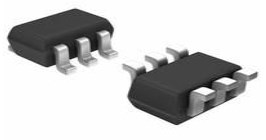
PMV40UN2R Package

PMV40UN2R Package
PMV40UN2R Manufacturer
Nexperia is a dedicated global leader in Discretes, Logic and MOSFETs devices. This new company became independent at the beginning of 2017. Focused on efficiency, Nexperia produces consistently reliable semiconductor components at a high volume: 85 billion annually. The company’s extensive portfolio meets the stringent standards set by the Automotive industry. And industry-leading small packages, produced in their own manufacturing facilities, combine power and thermal efficiency with best-in-class quality levels. Built on over half a century of expertise, Nexperia has 11,000 employees across Asia, Europe and the U.S. supporting
The related parts post:
PMV65XP Trench MOSFET: Datasheet, Alternatives, Pinout, SOT-23 and so on...
Specifications
- TypeParameter
- Factory Lead Time4 Weeks
- Package / Case
refers to the protective housing that encases an electronic component, providing mechanical support, electrical connections, and thermal management.
TO-236-3, SC-59, SOT-23-3 - Mounting Type
The "Mounting Type" in electronic components refers to the method used to attach or connect a component to a circuit board or other substrate, such as through-hole, surface-mount, or panel mount.
Surface Mount - Mount
In electronic components, the term "Mount" typically refers to the method or process of physically attaching or fixing a component onto a circuit board or other electronic device. This can involve soldering, adhesive bonding, or other techniques to secure the component in place. The mounting process is crucial for ensuring proper electrical connections and mechanical stability within the electronic system. Different components may have specific mounting requirements based on their size, shape, and function, and manufacturers provide guidelines for proper mounting procedures to ensure optimal performance and reliability of the electronic device.
Surface Mount - Transistor Element Material
The "Transistor Element Material" parameter in electronic components refers to the material used to construct the transistor within the component. Transistors are semiconductor devices that amplify or switch electronic signals and are a fundamental building block in electronic circuits. The material used for the transistor element can significantly impact the performance and characteristics of the component. Common materials used for transistor elements include silicon, germanium, and gallium arsenide, each with its own unique properties and suitability for different applications. The choice of transistor element material is crucial in designing electronic components to meet specific performance requirements such as speed, power efficiency, and temperature tolerance.
SILICON - Turn Off Delay Time
It is the time from when Vgs drops below 90% of the gate drive voltage to when the drain current drops below 90% of the load current. It is the delay before current starts to transition in the load, and depends on Rg. Ciss.
34 ns - Power Dissipation (Max)490mW Ta
- Number of Elements1
- Drive Voltage (Max Rds On, Min Rds On)1.8V 4.5V
- Current - Continuous Drain (Id) @ 25℃3.7A Ta
- Published1997
- Packaging
Semiconductor package is a carrier / shell used to contain and cover one or more semiconductor components or integrated circuits. The material of the shell can be metal, plastic, glass or ceramic.
Tape & Reel (TR) - Operating Temperature
The operating temperature is the range of ambient temperature within which a power supply, or any other electrical equipment, operate in. This ranges from a minimum operating temperature, to a peak or maximum operating temperature, outside which, the power supply may fail.
-55°C~150°C TJ - JESD-609 Code
The "JESD-609 Code" in electronic components refers to a standardized marking code that indicates the lead-free solder composition and finish of electronic components for compliance with environmental regulations.
e3 - Part Status
Parts can have many statuses as they progress through the configuration, analysis, review, and approval stages.
Active - Moisture Sensitivity Level (MSL)
Moisture Sensitivity Level (MSL) is a standardized rating that indicates the susceptibility of electronic components, particularly semiconductors, to moisture-induced damage during storage and the soldering process, defining the allowable exposure time to ambient conditions before they require special handling or baking to prevent failures
1 (Unlimited) - Number of Terminations3
- Resistance
Resistance is a fundamental property of electronic components that measures their opposition to the flow of electric current. It is denoted by the symbol "R" and is measured in ohms (Ω). Resistance is caused by the collisions of electrons with atoms in a material, which generates heat and reduces the flow of current. Components with higher resistance will impede the flow of current more than those with lower resistance. Resistance plays a crucial role in determining the behavior and functionality of electronic circuits, such as limiting current flow, voltage division, and controlling power dissipation.
36mOhm - Terminal Finish
Terminal Finish refers to the surface treatment applied to the terminals or leads of electronic components to enhance their performance and longevity. It can improve solderability, corrosion resistance, and overall reliability of the connection in electronic assemblies. Common finishes include nickel, gold, and tin, each possessing distinct properties suitable for various applications. The choice of terminal finish can significantly impact the durability and effectiveness of electronic devices.
Tin (Sn) - Terminal Position
In electronic components, the term "Terminal Position" refers to the physical location of the connection points on the component where external electrical connections can be made. These connection points, known as terminals, are typically used to attach wires, leads, or other components to the main body of the electronic component. The terminal position is important for ensuring proper connectivity and functionality of the component within a circuit. It is often specified in technical datasheets or component specifications to help designers and engineers understand how to properly integrate the component into their circuit designs.
DUAL - Terminal Form
Occurring at or forming the end of a series, succession, or the like; closing; concluding.
GULL WING - Peak Reflow Temperature (Cel)
Peak Reflow Temperature (Cel) is a parameter that specifies the maximum temperature at which an electronic component can be exposed during the reflow soldering process. Reflow soldering is a common method used to attach electronic components to a circuit board. The Peak Reflow Temperature is crucial because it ensures that the component is not damaged or degraded during the soldering process. Exceeding the specified Peak Reflow Temperature can lead to issues such as component failure, reduced performance, or even permanent damage to the component. It is important for manufacturers and assemblers to adhere to the recommended Peak Reflow Temperature to ensure the reliability and functionality of the electronic components.
260 - Time@Peak Reflow Temperature-Max (s)
Time@Peak Reflow Temperature-Max (s) refers to the maximum duration that an electronic component can be exposed to the peak reflow temperature during the soldering process, which is crucial for ensuring reliable solder joint formation without damaging the component.
30 - Pin Count
a count of all of the component leads (or pins)
3 - JESD-30 Code
JESD-30 Code refers to a standardized descriptive designation system established by JEDEC for semiconductor-device packages. This system provides a systematic method for generating designators that convey essential information about the package's physical characteristics, such as size and shape, which aids in component identification and selection. By using JESD-30 codes, manufacturers and engineers can ensure consistency and clarity in the specification of semiconductor packages across various applications and industries.
R-PDSO-G3 - Configuration
The parameter "Configuration" in electronic components refers to the specific arrangement or setup of the components within a circuit or system. It encompasses how individual elements are interconnected and their physical layout. Configuration can affect the functionality, performance, and efficiency of the electronic system, and may influence factors such as signal flow, impedance, and power distribution. Understanding the configuration is essential for design, troubleshooting, and optimizing electronic devices.
SINGLE WITH BUILT-IN DIODE - Number of Channels1
- Operating Mode
A phase of operation during the operation and maintenance stages of the life cycle of a facility.
ENHANCEMENT MODE - Power Dissipation
the process by which an electronic or electrical device produces heat (energy loss or waste) as an undesirable derivative of its primary action.
490mW - Turn On Delay Time
Turn-on delay, td(on), is the time taken to charge the input capacitance of the device before drain current conduction can start.
9 ns - FET Type
"FET Type" refers to the type of Field-Effect Transistor (FET) being used in an electronic component. FETs are three-terminal semiconductor devices that can be classified into different types based on their construction and operation. The main types of FETs include Metal-Oxide-Semiconductor FETs (MOSFETs), Junction FETs (JFETs), and Insulated-Gate Bipolar Transistors (IGBTs).Each type of FET has its own unique characteristics and applications. MOSFETs are commonly used in digital circuits due to their high input impedance and low power consumption. JFETs are often used in low-noise amplifiers and switching circuits. IGBTs combine the high input impedance of MOSFETs with the high current-carrying capability of bipolar transistors, making them suitable for high-power applications like motor control and power inverters.When selecting an electronic component, understanding the FET type is crucial as it determines the device's performance and suitability for a specific application. It is important to consider factors such as voltage ratings, current handling capabilities, switching speeds, and power dissipation when choosing the right FET type for a particular circuit design.
N-Channel - Transistor Application
In the context of electronic components, the parameter "Transistor Application" refers to the specific purpose or function for which a transistor is designed and used. Transistors are semiconductor devices that can amplify or switch electronic signals and are commonly used in various electronic circuits. The application of a transistor can vary widely depending on its design and characteristics, such as whether it is intended for audio amplification, digital logic, power control, or radio frequency applications. Understanding the transistor application is important for selecting the right type of transistor for a particular circuit or system to ensure optimal performance and functionality.
SWITCHING - Rds On (Max) @ Id, Vgs
Rds On (Max) @ Id, Vgs refers to the maximum on-resistance of a MOSFET or similar transistor when it is fully turned on or in the saturation region. It is specified at a given drain current (Id) and gate-source voltage (Vgs). This parameter indicates how much resistance the component will offer when conducting, impacting power loss and efficiency in a circuit. Lower Rds On values are preferred for better performance in switching applications.
44m Ω @ 3.7A, 4.5V - Vgs(th) (Max) @ Id
The parameter "Vgs(th) (Max) @ Id" in electronic components refers to the maximum gate-source threshold voltage at a specified drain current (Id). This parameter is commonly found in field-effect transistors (FETs) and is used to define the minimum voltage required at the gate terminal to turn on the transistor and allow current to flow from the drain to the source. The maximum value indicates the upper limit of this threshold voltage under specified operating conditions. It is an important parameter for determining the proper biasing and operating conditions of the FET in a circuit to ensure proper functionality and performance.
900mV @ 250μA - Input Capacitance (Ciss) (Max) @ Vds
The parameter "Input Capacitance (Ciss) (Max) @ Vds" in electronic components refers to the maximum input capacitance measured at a specific drain-source voltage (Vds). Input capacitance is a crucial parameter in field-effect transistors (FETs) and power MOSFETs, as it represents the total capacitance at the input terminal of the device. This capacitance affects the device's switching speed and overall performance, as it influences the time required for charging and discharging during operation. Manufacturers provide this parameter to help designers understand the device's input characteristics and make informed decisions when integrating it into a circuit.
635pF @ 15V - Gate Charge (Qg) (Max) @ Vgs
Gate Charge (Qg) (Max) @ Vgs refers to the maximum amount of charge that must be supplied to the gate of a MOSFET or similar device to fully turn it on, measured at a specific gate-source voltage (Vgs). This parameter is crucial for understanding the switching characteristics of the device, as it influences the speed at which the gate can charge and discharge. A higher gate charge value often implies slower switching speeds, which can impact the efficiency of high-frequency applications. This parameter is typically specified in nanocoulombs (nC) in the component's datasheet.
12nC @ 4.5V - Vgs (Max)
Vgs (Max) refers to the maximum gate-source voltage that can be applied to a field-effect transistor (FET) without causing damage to the component. This parameter is crucial in determining the safe operating limits of the FET and helps prevent overvoltage conditions that could lead to device failure. Exceeding the specified Vgs (Max) rating can result in breakdown of the gate oxide layer, leading to permanent damage to the FET. Designers must ensure that the applied gate-source voltage does not exceed the maximum rating to ensure reliable and long-term operation of the electronic component.
±12V - Continuous Drain Current (ID)
Continuous Drain Current (ID) is a key parameter in electronic components, particularly in field-effect transistors (FETs) such as MOSFETs. It refers to the maximum current that can flow continuously through the drain terminal of the FET without causing damage to the component. This parameter is crucial for determining the power handling capability of the FET and is specified by the manufacturer in the component's datasheet. Designers must ensure that the actual operating current does not exceed the specified Continuous Drain Current to prevent overheating and potential failure of the component.
3.7A - Threshold Voltage
The threshold voltage is a critical parameter in electronic components, particularly in field-effect transistors (FETs). It refers to the minimum voltage required at the input terminal of the FET to turn it on and allow current to flow between the source and drain terminals. Below the threshold voltage, the FET remains in the off state, acting as an open switch. Once the threshold voltage is exceeded, the FET enters the on state, conducting current between the source and drain.The threshold voltage is a key factor in determining the operating characteristics of FETs, such as their switching speed and power consumption. It is typically specified by the manufacturer and can vary depending on the specific type of FET and its design. Designers must consider the threshold voltage when selecting FETs for a particular application to ensure proper functionality and performance.
400mV - JEDEC-95 Code
JEDEC-95 Code is a standardized identification system used by the Joint Electron Device Engineering Council to categorize and describe semiconductor devices. This code provides a unique alphanumeric identifier for various memory components, ensuring consistency in documentation and communication across the electronics industry. The format includes information about the type, capacity, and technology of the device, facilitating easier specification and understanding for manufacturers and engineers.
TO-236AB - Gate to Source Voltage (Vgs)
The Gate to Source Voltage (Vgs) is a crucial parameter in electronic components, particularly in field-effect transistors (FETs) such as MOSFETs. It refers to the voltage difference between the gate and source terminals of the FET. This voltage determines the conductivity of the FET and controls the flow of current through the device. By varying the Vgs, the FET can be switched on or off, allowing for precise control of electronic circuits. Understanding and properly managing the Vgs is essential for ensuring the reliable and efficient operation of FET-based circuits.
12V - Drain to Source Breakdown Voltage
Drain to Source Breakdown Voltage, often denoted as V(BR) D-S, is a critical parameter in electronic components, particularly in field-effect transistors (FETs) and metal-oxide-semiconductor FETs (MOSFETs). It represents the maximum voltage that can be applied between the drain and source terminals of the device without causing breakdown or permanent damage. Exceeding this voltage can lead to excessive current flow, resulting in thermal failure or destruction of the component. It is essential for ensuring reliable operation in circuit designs where high voltages may be encountered.
30V - Max Junction Temperature (Tj)
Max Junction Temperature (Tj) refers to the maximum allowable temperature at the junction of a semiconductor device, such as a transistor or integrated circuit. It is a critical parameter that influences the performance, reliability, and lifespan of the component. Exceeding this temperature can lead to thermal runaway, breakdown, or permanent damage to the device. Proper thermal management is essential to ensure the junction temperature remains within safe operating limits during device operation.
150°C - Ambient Temperature Range High
This varies from person to person, but it is somewhere between 68 and 77 degrees F on average. The temperature setting that is comfortable for an individual may fluctuate with humidity and outside temperature as well. The temperature of an air conditioned room can also be considered ambient temperature.
150°C - Height1.1mm
- RoHS Status
RoHS means “Restriction of Certain Hazardous Substances” in the “Hazardous Substances Directive” in electrical and electronic equipment.
ROHS3 Compliant - Lead Free
Lead Free is a term used to describe electronic components that do not contain lead as part of their composition. Lead is a toxic material that can have harmful effects on human health and the environment, so the electronics industry has been moving towards lead-free components to reduce these risks. Lead-free components are typically made using alternative materials such as silver, copper, and tin. Manufacturers must comply with regulations such as the Restriction of Hazardous Substances (RoHS) directive to ensure that their products are lead-free and environmentally friendly.
Lead Free
Parts with Similar Specs
- ImagePart NumberManufacturerMountPackage / CaseContinuous Drain Current (ID)Current - Continuous Drain (Id) @ 25°CGate to Source Voltage (Vgs)Power DissipationPower Dissipation-MaxMounting TypeView Compare
![PMV40UN2R]()
PMV40UN2R
Surface Mount
TO-236-3, SC-59, SOT-23-3
3.7 A
3.7A (Ta)
12 V
490 mW
490mW (Ta)
Surface Mount
![DMG3402L-7]()
Surface Mount
TO-236-3, SC-59, SOT-23-3
4.2 A
4.2A (Ta)
20 V
-
780mW (Ta)
Surface Mount
![DMP3056L-7]()
Surface Mount
TO-236-3, SC-59, SOT-23-3
-4.3 A
4.3A (Ta)
25 V
1.38 W
1.38W (Ta)
Surface Mount
![FDN372S]()
Surface Mount
TO-236-3, SC-59, SOT-23-3
2.6 A
2.6A (Ta)
16 V
500 mW
500mW (Ta)
Surface Mount
![DMN3070SSN-7]()
Surface Mount
TO-236-3, SC-59, SOT-23-3
4 A
4A (Ta)
12 V
-
1.4W (Ta)
Surface Mount


Datasheet PDF
- PCN Packaging :
- Datasheets :
- ReachStatement :
Trend Analysis
What is an N-channel enhancement mode Field-Effect Transistor?
PMV40UN2R.
What is the difference between field-effect transistor and junction field-effect transistor?
FETs have very high input resistances so very little or no current (MOSFET types) flows into the input terminal making them ideal for use as electronic switches. ... FETs have a very large current gain compared to junction transistors.
Why FET is preferred over transistor?
Since this input impedance is considerably higher than that of BJTs, FETs are preferred over BJTs for use as the input stage to a multistage amplifier. One class of FETs (JFETs) generates lower noise than BJTs. FETs are more temperature stable than BJTs. FETs are generally easier to fabricate than BJTs.
What are the advantages of FET?
Advantages of FET :
FET has a high input impedance of several megaohms.
FET has less effect by radiation than BJT.
Temperature stable than BJT.
Less noise compares to BJT.
Can be fabricated with less processing.
Smaller in size.
Longer life.
High efficiency.
 SI5340 Clock Generator: Pinout, Features and Datasheet
05 January 20221671
 STM32H743: Detailed Datasheet, Pinout, and Alternatives Guide
23 January 20261100
![CR1216 3 V Battery Non-Rechargeable[Video]: Datasheet, CR1216 VS CR2016, and Equivalents](https://res.utmel.com/Images/Article/0b54a9ba-2bd8-4e1e-993a-827e6c746ece.png) CR1216 3 V Battery Non-Rechargeable[Video]: Datasheet, CR1216 VS CR2016, and Equivalents
CR1216 3 V Battery Non-Rechargeable[Video]: Datasheet, CR1216 VS CR2016, and Equivalents01 April 20223806
 A General Introduction to TPS40140RHHT Synchronous Buck Controller
23 April 2022813
 SN74LVC2G17DCKR Dual Schmitt-Trigger Buffer: Circuit, Pinout, and Datasheet
29 March 20222910
 2N5401 PNP Transistor: Pinout, Datasheet, and Equivalents
06 July 202126191
 TLC5940NT LED Driver: Features, Speicifications and Applications
27 May 20211837
 LM7912 Negative Regulators: Diagram, Pinout and Datasheet
02 August 20216207
 The Art of Microchips: A Journey from Sand to Silicon
12 September 20233843
 Software Tools for NXP Microcontroller Development
06 June 20251181
 Protect USB Ports From Nefarious USB Killers
15 November 20191593
 0 Ohm Resistor Explained
10 December 202117986
 STMicroelectronics: The European Powerhouse in Silicon Carbide Semiconductor Technology
05 October 20233035
 A/D Converter: Basic Principle and Types
06 November 202019566
 In-depth Analysis of the Global Semiconductor Supply Chain
20 January 202212469
 How to Distinguish MOSFET? Is it N-Channel or P-Channel?
23 December 202110478
Nexperia USA Inc.
In Stock: 12007
Minimum: 1 Multiples: 1
Qty
Unit Price
Ext Price
1
$0.086978
$0.09
10
$0.082055
$0.82
100
$0.077410
$7.74
500
$0.073029
$36.51
1000
$0.068895
$68.90
Not the price you want? Send RFQ Now and we'll contact you ASAP.
Inquire for More Quantity
![2N7002,215]() 2N7002,215
2N7002,215Nexperia USA Inc.
![2N7002P,215]() 2N7002P,215
2N7002P,215Nexperia USA Inc.
![PMZ350UPEYL]() PMZ350UPEYL
PMZ350UPEYLNexperia USA Inc.
![PSMN4R8-100BSEJ]() PSMN4R8-100BSEJ
PSMN4R8-100BSEJNexperia USA Inc.
![BSS84,215]() BSS84,215
BSS84,215Nexperia USA Inc.
![BSS138AKAR]() BSS138AKAR
BSS138AKARNexperia USA Inc.
![BUK98150-55A/CUF]() BUK98150-55A/CUF
BUK98150-55A/CUFNexperia USA Inc.
![NX3008NBKW,115]() NX3008NBKW,115
NX3008NBKW,115Nexperia USA Inc.
![BSH205G2R]() BSH205G2R
BSH205G2RNexperia USA Inc.


