
 Product
 Brand
Brand Articles
 Tools
Tools
Capacitor Networks Complete Guide: From Basic Calculations to Advanced Applications
Table of Contents
1.1 Capacitors in Series Formula
1.3 Charge Distribution in Capacitor Networks
2.1 What is a Capacitor Network
3.0 Series-Parallel Circuit Problems and Solutions
1.0 How to Calculate Equivalent Capacitance
Calculating equivalent capacitance is the cornerstone of capacitor network analysis. Understanding this fundamental concept allows you to simplify complex circuits into manageable calculations, making it easier to predict circuit behavior and optimize designs.
The equivalent capacitance represents the total capacitive effect of multiple capacitors as if they were replaced by a single capacitor. This simplified approach is essential for analyzing circuits in power electronics, signal filtering, and energy storage applications.
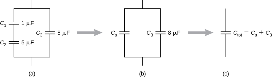
Figure 1: Basic capacitor network configurations showing series and parallel combinations
Professional Tip: Always identify series and parallel sections separately before attempting to calculate the overall equivalent capacitance. Start with the innermost combinations and work outward.
1.1 Capacitors in Series Formula
When capacitors are connected in series, the equivalent capacitance is calculated using the reciprocal formula:
1/Cs = 1/C₁ + 1/C₂ + 1/C₃ + …
This formula follows the same pattern as resistors in parallel. The key characteristics of series capacitor circuits include:
Same charge on all capacitors (Q₁ = Q₂ = Q₃)
Different voltage drops across each capacitor
Total capacitance is always less than the smallest individual capacitor
For two capacitors in series, you can use the simplified formula: Cs = (C₁ × C₂)/(C₁ + C₂)
| Number of Capacitors | Formula | Example (10μF, 20μF) |
|---|---|---|
| Two capacitors | C₁C₂/(C₁+C₂) | (10×20)/(10+20) = 6.67μF |
| Three or more | 1/Cs = Σ(1/Ci) | Calculate reciprocals first |
Important Note: The equivalent capacitance in series is always dominated by the smallest capacitor value. This principle is crucial when designing timing circuits and voltage dividers.
1.2 Capacitors in Parallel Formula
Parallel capacitor combinations follow a much simpler calculation rule:
Cp = C₁ + C₂ + C₃ + …
The characteristics of capacitors in parallel include:
Same voltage across all capacitors
Different charges on each capacitor
Total capacitance equals the sum of individual capacitances
This configuration is commonly used in power supply filtering and energy storage applications where higher capacitance values are needed.
1.3 Charge Distribution in Capacitor Networks
Understanding charge distribution is critical for analyzing capacitor network behavior. In series circuits, the fundamental principle states:
Q = Q₁ = Q₂ = Q₃ (same charge on all capacitors)
This occurs because charge conservation requires that electrons removed from one plate must appear on the adjacent plate. The voltage across each capacitor depends on its individual capacitance:
V₁ = Q/C₁, V₂ = Q/C₂, V₃ = Q/C₃
In parallel circuits, each capacitor can store different amounts of charge: Qtotal = Q₁ + Q₂ + Q₃
1.4 Voltage Distribution Across Series Capacitors
Voltage distribution in series capacitors follows the capacitive voltage divider principle. For two capacitors in series:
V₁ = Vs × (C₂/(C₁ + C₂)) V₂ = Vs × (C₁/(C₁ + C₂))
Notice that the larger capacitor receives the smaller voltage, which is opposite to resistive voltage dividers. This principle is utilized in AC coupling circuits and high-voltage applications.
##
2.0 Capacitor Networks: Series and Parallel Analysis
Understanding the fundamental differences between series and parallel capacitor networks is essential for circuit design and analysis. Each configuration offers distinct advantages and is suited for specific applications in modern electronics.
2.1 What is a Capacitor Network
A capacitor network is an arrangement of two or more capacitors connected in various configurations to achieve specific electrical characteristics. These networks can be found in virtually every electronic device, from simple timing circuits to complex power management systems.
The primary types include:
Simple series networks - capacitors connected end-to-end
Simple parallel networks - capacitors connected across the same voltage points
Complex networks - combinations of series and parallel sections
Bridge networks - requiring special analysis techniques
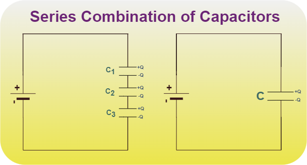
Figure 2: Different types of capacitor network configurations
2.2 Types of Capacitor Combinations
Modern capacitor combinations serve various purposes in electronic circuits:
Series Combinations
Voltage division
High-voltage applications
Precision timing
Parallel Combinations
Increased capacitance
Current sharing
Noise filtering
Series-Parallel Combinations
Impedance matching
Filter networks
Energy storage systems
Delta and Wye Configurations
Three-phase systems
Complex impedance networks
Motor starting circuits
Understanding these configurations helps engineers select appropriate designs for power electronics applications.
2.3 Why Connect Capacitors in Parallel
Connecting capacitors in parallel offers several compelling advantages:
Increased Total Capacitance: The most obvious benefit is achieving higher capacitance values than available in single components. This is particularly useful in power supply filtering where large capacitance values are needed.
Current Sharing: Parallel capacitors share the AC current, reducing the stress on individual components and improving reliability. This principle is crucial in high-frequency applications where current handling capacity is limited.
Reduced Equivalent Series Resistance (ESR): Multiple parallel capacitors effectively reduce the total ESR, improving performance in switching power supplies and RF circuits.
Redundancy: If one capacitor fails, others continue to provide circuit functionality, enhancing system reliability in critical applications.
Real-World Example: Computer motherboards use multiple parallel capacitors near the CPU to provide stable power delivery during high-current transients. Without this configuration, voltage fluctuations would cause system instability.
2.4 Why Connect Capacitors in Series
Series capacitor connections serve specific purposes that parallel configurations cannot achieve:
Voltage Rating Increase: When individual capacitors cannot handle the required voltage, series connection allows the total voltage to be divided among multiple components. This is essential in high-voltage power supplies and industrial equipment.
Precise Capacitance Values: By combining standard values in series, engineers can achieve non-standard capacitance values for precision timing circuits and filter applications.
Voltage Division: Series capacitors create voltage dividers for AC coupling and signal processing applications.
Impedance Matching: In RF applications, series capacitors help match impedances between different circuit sections.
Important Consideration: Remember that series capacitors require voltage balancing in DC applications to prevent individual components from experiencing excessive voltage stress.
3.0 Series-Parallel Circuit Problems and Solutions
Complex capacitor networks combining both series and parallel elements require systematic analysis approaches. These circuits are common in real-world applications, from audio crossover networks to power factor correction systems.
The key to solving series-parallel capacitor problems lies in identifying and simplifying sections methodically, working from the innermost combinations outward.
###
3.1 Energy Stored in Capacitor Networks
Energy storage in capacitor networks depends on both the configuration and the charge distribution. The fundamental energy equation for a single capacitor is:
E = ½CV² = ½QV = Q²/2C
For series networks, the total energy equals the sum of individual energies: Etotal = E₁ + E₂ + E₃ + …
However, the energy distribution is not uniform. Smaller capacitors in series store more energy per unit capacitance due to higher voltage drops.
For parallel networks, energy calculation is more straightforward since all capacitors experience the same voltage: Etotal = ½(C₁ + C₂ + C₃)V²
| Configuration | Energy Distribution | Design Consideration |
|---|---|---|
| Series | Higher energy in smaller caps | Voltage rating critical |
| Parallel | Energy proportional to capacitance | Current rating important |
| Mixed | Complex calculation required | Use simulation tools |
Professional Insight: In energy storage applications like electric vehicle charging systems, parallel configurations are preferred for maximum energy density, while series configurations are used for voltage stepping.
3.2 Troubleshooting Capacitor Networks
Troubleshooting capacitor networks requires systematic diagnostic approaches to identify failed components and circuit problems. Common issues include:
Visual Inspection Checklist:
Bulging or swelling capacitor cases
Electrolyte leakage around terminals
Discoloration or burn marks
Cracked ceramic capacitors
Loose connections or corrosion
Electrical Testing Procedures:
Capacitance Measurement: Use an LCR meter to verify individual capacitor values
ESR Testing: High ESR indicates aging or damage in electrolytic capacitors
Leakage Testing: Measure DC resistance to identify leaky capacitors
Voltage Distribution: Check if voltage divides properly in series circuits
Common Failure Modes:
Open Circuit: Complete loss of capacitance
Short Circuit: Zero or very low resistance
High ESR: Reduced effectiveness in filtering applications
Reduced Capacitance: Aging or temperature effects
Troubleshooting Tip: In series networks, one failed capacitor can affect the entire circuit. Always test each component individually when diagnosing network problems.
For detailed troubleshooting procedures, refer to industry standard testing methods.
3.3 Delta-Star Transformation for Capacitors
Delta-Star transformation (also called Y-Δ conversion) is essential for analyzing complex capacitor networks that cannot be simplified using basic series-parallel rules.
Delta to Star Conversion Formulas:
C₁ = (CₐCᵦ)/(Cₐ + Cᵦ + Cᵧ) C₂ = (CᵦCᵧ)/(Cₐ + Cᵦ + Cᵧ) C₃ = (CᵧCₐ)/(Cₐ + Cᵦ + Cᵧ)
Star to Delta Conversion Formulas:
Cₐ = (C₁C₂ + C₂C₃ + C₃C₁)/C₃ Cᵦ = (C₁C₂ + C₂C₃ + C₃C₁)/C₁ Cᵧ = (C₁C₂ + C₂C₃ + C₃C₁)/C₂
These transformations are particularly useful in three-phase power systems and complex filter networks where standard analysis methods fail. The Physics LibreTexts provides detailed mathematical proofs for these conversions.
4.0 Capacitor Network Calculators and Tools
Modern capacitor network analysis benefits greatly from digital tools and calculators that speed up complex calculations and reduce errors. These tools range from simple online calculators to sophisticated circuit simulation software.
4.1 Applications of Capacitor Networks
Capacitor networks find applications across numerous industries and technologies:
Power Electronics Applications:
Power Factor Correction: Large capacitor banks improve system efficiency
DC Link Filtering: Smoothing ripple in switch-mode power supplies
Energy Storage: Grid-scale energy storage systems
Motor Starting: Providing additional torque for AC motors
Signal Processing Applications:
Audio Crossovers: Separating frequency ranges in speaker systems
RF Filters: Bandwidth limiting and impedance matching
Timing Circuits: Precision oscillators and delay circuits
Coupling Networks: DC blocking in amplifier stages
Automotive Applications:
Engine Management: Ignition system energy storage
Electric Vehicle Charging: High-voltage energy storage
Infotainment Systems: Audio filtering and power management
Safety Systems: Backup power for critical circuits
The KEMET Corporation provides extensive documentation on filtering applications in power supply design.
4.2 Online Capacitor Network Simulators
Digital simulation tools have revolutionized capacitor network design and analysis:
Professional Simulation Software:
SPICE-based simulators: LTSpice, PSpice, Multisim
Online simulators: CircuitLab, Falstad Circuit Simulator
Specialized tools: KEMET’s KSIM for capacitor-specific simulations
Educational Tools:
PhET Interactive Simulations: University of Colorado’s capacitor lab
Circuit analysis apps: Mobile applications for quick calculations
Web-based calculators: Instant series/parallel calculations
| Tool Type | Best For | Cost | Accuracy |
|---|---|---|---|
| Professional SPICE | Complex design validation | High | Excellent |
| Online simulators | Quick prototyping | Free/Low | Good |
| Mobile apps | Field calculations | Free | Basic |
| Educational tools | Learning concepts | Free | Good |
Simulation Best Practices:
Always verify hand calculations with simulation results
Include parasitic effects for high-frequency analysis
Use Monte Carlo analysis for component tolerance effects
Validate simulations with physical measurements when possible
The Digikey Conversion Calculator offers reliable online calculations for basic series and parallel combinations.
4.3 Capacitor Color Code Calculator
While ceramic and film capacitors often use numerical codes, some older or specialized capacitors still use color coding systems. Understanding these codes is essential for circuit analysis and component identification.
Standard Capacitor Color Codes:
First Band: First significant digit
Second Band: Second significant digit
Third Band: Multiplier (number of zeros)
Fourth Band: Tolerance
Fifth Band: Voltage rating (if present)
Color Value Chart:
Black: 0, Brown: 1, Red: 2, Orange: 3, Yellow: 4
Green: 5, Blue: 6, Violet: 7, Grey: 8, White: 9
Modern Marking Systems: Most contemporary capacitors use numerical coding that directly indicates capacitance values in picofarads. For example:
“104” = 10 × 10⁴ pF = 100,000 pF = 0.1 μF
“223” = 22 × 10³ pF = 22,000 pF = 0.022 μF
Professional Component Selection: When working with electronic components, always verify specifications using manufacturer datasheets rather than relying solely on color codes or basic markings.
Common Capacitor Network Pitfalls
Throughout my years of circuit design experience, I’ve encountered several recurring mistakes that can derail even well-planned projects:
Voltage Rating Misconceptions: Many engineers assume that series capacitors automatically handle higher voltages safely. However, without proper voltage balancing resistors, individual capacitors may experience voltage stress exceeding their ratings.
Tolerance Accumulation: In precision applications, capacitor tolerances can accumulate unexpectedly. A ±10% tolerance on individual components can result in ±30% variation in complex networks.
Temperature Effects: Capacitor values change significantly with temperature, especially ceramic types. This effect is often overlooked in initial designs but becomes critical in automotive and industrial applications.
ESR Neglect: Equivalent Series Resistance becomes crucial in high-frequency and high-current applications. Parallel combinations don’t always reduce ESR as expected if connections introduce additional resistance.
Purchasing Guide: Selecting Capacitors for Network Applications
When building capacitor networks, component selection significantly impacts performance and reliability:
For Series Applications:
Choose components with identical voltage ratings
Consider derating to 50-70% of maximum voltage
Select low-leakage types for DC applications
Include voltage balancing resistors for safety
For Parallel Applications:
Match ESR values when possible
Ensure adequate current handling capacity
Consider physical size and mounting constraints
Verify temperature coefficients match application needs
Quality Indicators:
Manufacturer reputation and certifications
Detailed specifications and test data
Appropriate safety agency approvals
Traceability and batch coding
FAQ Section
Q: Can I mix different types of capacitors in the same network? A: While technically possible, mixing capacitor types (ceramic, electrolytic, film) can introduce unexpected behavior due to different temperature coefficients, ESR values, and aging characteristics. It’s generally better to use the same type and manufacturer when possible.
Q: How do I calculate the equivalent capacitance of a complex network with both series and parallel sections? A: Start by identifying the innermost series or parallel groups, calculate their equivalent values, then work outward. Replace each simplified section with its equivalent until you have a single capacitor value.
Q: What happens if one capacitor in a series network fails open? A: An open capacitor in series breaks the entire circuit, resulting in zero total capacitance. This is why reliability analysis is crucial in series configurations.
Q: Do capacitors in parallel always share current equally? A: Not necessarily. Current sharing depends on the impedance of each branch, which includes both capacitive reactance and ESR. At high frequencies, ESR differences can cause significant current imbalance.
Q: How do I determine if my capacitor network calculations are correct? A: Always verify calculations using multiple methods: hand calculations, simulation software, and when possible, physical measurements. The three results should agree within expected tolerances.
Conclusion
Mastering capacitor networks requires understanding both fundamental principles and practical applications. From basic series and parallel calculations to complex delta-star transformations, these concepts form the foundation of modern electronic design.
Key takeaways for successful capacitor network implementation include systematic analysis approaches, proper component selection, and thorough testing procedures. As electronic systems become increasingly complex, the ability to analyze and design effective capacitor networks becomes even more valuable.
The future of capacitor network design lies in advanced simulation tools, improved component technologies, and better understanding of high-frequency effects. By building strong fundamentals today, engineers can adapt to tomorrow’s challenges in power electronics, renewable energy systems, and advanced communication technologies.
Whether you’re designing your first circuit or optimizing an existing system, remember that successful capacitor network implementation combines theoretical knowledge with practical experience. Continue learning, experimenting, and staying current with industry developments to maintain your competitive edge in this rapidly evolving field.
Take Action Today: Start by practicing with simple series and parallel calculations, then gradually work up to more complex networks. Use simulation tools to verify your understanding, and don’t hesitate to consult manufacturer resources and application notes for specific component guidance
 UTMEL
UTMEL
We are the professional distributor of electronic components, providing a large variety of products to save you a lot of time, effort, and cost with our efficient self-customized service. careful order preparation fast delivery service
 AI Server MLCCs: Why NVIDIA Rubin Racks Require Over 600,000 CapacitorsUTMEL02 June 20261760
Next-generation AI servers like NVIDIA's Rubin architecture require over 600,000 MLCCs per rack due to extreme power densities exceeding 120kW. This transition from GB300 demands high-capacitance, low-ESR capacitors with X7R/X7S dielectrics to handle intense transient responses and thermal loads, forcing procurement teams to navigate extended 24-week lead times for these specialized components.
Read More What is Feedthrough Capacitor?UTMEL06 November 202141090
Hello, everyone. I am Rose. Today I will introduce the feedthrough capacitor to you. The feedthrough capacitor is a three-terminal capacitor that is used to reduce high frequencies. The feedthrough capacitor, unlike regular three-terminal capacitors, is directly installed on the metal panel, resulting in a lower grounding inductance and a negligible effect on the lead inductance.
Read More Detailed Explanation About Twenty Kinds of CapacitorUTMEL08 November 20219162
Hello everyone, I am Rose. Today I will introduce 20 kinds of capacitor to you. I will illustrate them in three or four aspects: Structure, features, Usages, advantages and disadvantages.
Read More What is a Polypropylene Capacitor?UTMEL08 November 202121518
A polypropylene capacitor is a kind of capacitor with a very stable electric capacity. It is often used in applications requiring very precise capacitance and can replace most polyphenylene or mica capacitors.
Read More What is the Difference between MOM, MIM and MOS Capacitors?UTMEL17 April 202569696
This article mainly introduces the structure, principle, advantages and disadvantages of MOM, MIM and MOS capacitors and the difference between them.
Read More
Subscribe to Utmel !
![FBP-PIC18-Q40-Q41-ISO26262]() FBP-PIC18-Q40-Q41-ISO26262
FBP-PIC18-Q40-Q41-ISO26262Microchip Technology
![MIKROE-4943]() MIKROE-4943
MIKROE-4943MikroElektronika
![MIKROE-4987]() MIKROE-4987
MIKROE-4987MikroElektronika
![MIKROE-4942]() MIKROE-4942
MIKROE-4942MikroElektronika
![MIKROE-5065]() MIKROE-5065
MIKROE-5065MikroElektronika
![MIKROE-4965]() MIKROE-4965
MIKROE-4965MikroElektronika
![MIKROE-5053]() MIKROE-5053
MIKROE-5053MikroElektronika
![MIKROE-4876]() MIKROE-4876
MIKROE-4876MikroElektronika
![MIKROE-4933]() MIKROE-4933
MIKROE-4933MikroElektronika
![MIKROE-4824]() MIKROE-4824
MIKROE-4824MikroElektronika
